Service Source iMac G5, 20-inch Updated 5 December 2007 © 2005 Apple Computer, Inc. All rights reserved.
Service Source Take Apart iMac G5 (20-inch) © 2004 Apple Computer, Inc. All rights reserved.
General Information What’s New October 2007 Updated Logic Board replacement procedure. A “caution” was added to notify service providers not to twist, flex, or bend the iMac G5 logic as you install to board into the chassis. Flexing the board may jeopardize the thermal interface between the heatsink and the processor. Refer to the iMac logic board inbox notice 073-1158 for additional information.
Important Things to Know 1. All customer removable screws are brass colored (except for some fan screws on earlier units which use torx screws). Do not remove screws unless they are brass colored, or you will void your warranty. 2. Important: Ground yourself when working on the computer. The procedure will show you how to ground yourself. 3. Important: Memory DIMM connector latches are fragile and need to be handled carefully when removing the inverter and logic board.
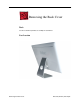
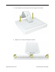
Removing the Back Cover Tools Use the screwdriver provided, or a Phillips #1 screwdriver Part Location Removing the Back Cover iMac G5 (20-inch) Take Apart -
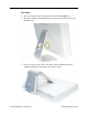
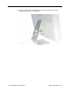
Procedure 1. Turn your computer off by choosing Shut down from the Apple (K) menu. 2. Disconnect all cables, and unplug the power cord from your computer. Put on your ESD Wrist strap 3. Place a soft, clean towel or cloth on the desk or surface. Hold the sides of the computer and slowly lay the computer face down as shown.
4. Locate the three case screws circled below. You may have to lift the metal foot to locate the middle case screw. Note: These screws are captive; they are part of the display/bezel assembly and cannot be removed. 5. Using the tool provided, or a Phillips #1 screwdriver, loosen the three captive screws. Note: Turn the screws counterclockwise until they stop turning. 6. Holding the back cover by the metal foot, tilt the cover up and lift it off the computer.
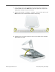
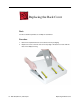
Replacing the Back Cover Tools Use the screwdriver provided, or a Phillips #1 screwdriver Procedure 1. Remove the replacement back cover and foot from its packaging. 2. Replace the cover so that the slots on the top edge of the back cover mate with the tabs on the display housing.
3. Lower and press the cover into place until it fits snugly on the computer. 4. Tighten the case screws by turning them clockwise.
5. Position the computer in the upright position. Reconnect the power cord and remaining cables.
Serial ATA Hard Drive Tools • Use the screwdriver provided, or a Phillips #1 screwdriver, preferably with a magnetized tip • Needlenose pliers • Screw tray or equivalent to hold the screws Preliminary Steps Before you begin, remove the back cover.
Removing the Serial ATA Hard Drive 1. To access the hard drive you must first remove other service modules. This procedure will show you how to remove and replace these modules. Note: As you remove each module, set it aside, along with the screws for that module. 2. Ground yourself. Touch the metal surface (as shown below) on the inside of the computer to discharge any static electricity. Warning: Always discharge static electricity before you touch any parts or install any components inside the computer.
3. Locate the hard drive near the top right corner. 4. Remove the three hard drive screws. Set the screws aside.
5. Lift the hard drive straight up, about one inch, to access the connector shown below. Disconnect the black connector from the side of the hard drive. Note: Do not disconnect the other end of the cable from the board. 6. Disconnect the drive data cable and power cable from the hard drive. Lift the hard drive up and out of the midplane assembly.Important: Return this hard drive to Apple in the packaging provided.
Replacing the Serial ATA Hard Drive 1. Remove the replacement hard drive from its packaging. 2. Connect the drive data cable and power cable to the hard drive. Lower the hard drive into place on the midplane. 3. Connect the black cable to the white connector on the side of the hard drive.
4. Replace the three hard drive screws.
Optical Drive Tools • Use the screwdriver provided, or a Phillips #1 screwdriver, preferably with a magnetized tip • Screw tray or equivalent to hold the screws Preliminary Steps Before you begin, remove the back cover.
Removing the Optical Drive 1. Ground yourself. Touch the metal surface (as shown below) on the inside of the computer to discharge any static electricity. Warning: Always discharge static electricity before you touch any parts or install any components inside the computer. To avoid generating static electricity, do not walk around the room until you have finished installing the part and closed the computer.
2. Locate the optical drive in the top left corner. 3. Using the tool provided, or a Phillips #1 screwdriver, remove the four optical drive screws circled below. Set the screws aside.
4. Pull the optical drive tab straight up and then to the right. Set the optical drive aside. 5. Important: Return this optical drive to Apple in the packaging provided.
Replacing the Optical Drive 1. Note: A microfoam insert is included with the replacement optical drive and should be installed using the instructions included below. The microfoam insert will prevent optical media from ejecting out of the system and dropping to the desktop. Only one microfoam insert should be used per system 2. Locate the enclosed piece of white microfoam and the two white posts (circled) on the bezel. 3.
4. Tuck the mircofoam into place before installing the optical drive. 5. Remove the replacement optical drive from its packaging. 6. Replace the optical drive in the direction of the arrow, lining up the white posts on the bezel with the holes on the optical drive bezel.
7. The optical drive will click into place when you push down near the pull tab. Note: If the optical drive is not seated accurately, the optical drive may not function. 8. Make sure no microfoam is sticking out of the bezel. Note: Before reassembling the computer, partially insert an optical disc to make sure it inserts smoothly.
9. Replace the four optical drive screws.
Microfoam Shim Tools Required • Use the screwdriver provided, or a Phillips #2 screwdriver, preferably with a magnetized tip • Screw tray or equivalent to hold the screws Preliminary Steps Before you begin, remove the back cover and the optical drive. Part Location Note: The education models do not have an optical drive.
Installing the Microfoam onto the Bezel 1. Steps 2-7 show photos of the microfoam inside the iMac G5 20-inch computer. The installation procedure is the same for the 17-inch computer. Go on to the next step. 2. Locate the piece of microfoam and the two white posts (circled) on the bezel. 3. With the shiny side of the microfoam facing the bezel, slide the holes of the microfoam onto the two white posts on the bezel.
4. Tuck the mircofoam into place before installing the optical drive. 5. Replace the optical drive in the direction of the arrow, lining up the white posts on the bezel with the holes on the optical drive bezel.
6. Slide the optical drive into place and press down near the tab to reconnect the drive. 7. Make sure no microfoam is sticking out of the bezel. Note: Before reassembling the computer, partially insert an optical disc to make sure it inserts smoothly. 8. Replace the optical drive screws. 9. Replace the back cover.
Inverter Tools Required • Use the screwdriver provided, or a Phillips #1 screwdriver, preferably with a magnetized tip • Needlenose pliers • Screw tray or equivalent to hold the screws Preliminary Steps Before you begin, remove the back cover. Part Location Important: When removing the inverter, be careful of the memory DIMM connector latches. They are fragile and need to be handled carefully. Also note that packing the logic board in the proper service packing is very important.
Removing the Inverter 1. To access the inverter other service modules have to be removed. This procedure will show you how to remove and replace each module. As you remove each module, set it aside, along with the screws for that module. 2. Ground yourself. Touch the metal surface (as shown below) on the inside of the computer to discharge any static electricity. Warning: Always discharge static electricity before you touch any parts or install any components inside the computer.
3. Locate the hard drive near the top right corner. 4. Disconnect the black cable from the white connector on the side of the hard drive near the memory. Note: Do not disconnect the other end of the cable. Leave the hard drive in place.
5. Locate the memory module(s) in the bottom right corner. You must remove the memory to gain access to the inverter. 6. Rotate the computer counterclockwise so the memory is in the position shown below. 7. To release the memory from its slot, push down on the two side latches (circled below). Then pull the memory module out of the slot. Repeat this step if you have a second memory module.
8. Locate the gray plastic module on the right side of the computer. This is the inverter. 9. Remove the three inverter screws (circled below).
10. Rotate the computer clockwise so you see the inverter cables as shown below. Tilt the inverter to access the two white cable connectors with the pink and blue cables. 11. Disconnect the cables by pulling on the connector, not on the cables. Disconnect the smaller connector first. 12. Important: When removing the inverter, be careful of the memory DIMM connector latches. Carefully slide out the inverter without making contact with the DIMM connector latches.
13. Locate the small, gray inverter cable cover in the top right corner. To unhook the cover, pull it in the direction of the arrow shown below. 14. Disconnect the two white connectors underneath the cover. Pull on the connectors, not on the cables. Free the cables from the clips inside the cover. Set the inverter and cable cover aside.
15. Turn over the inverter as shown. Using your fingers or a flatblade screwdriver, remove the gray plastic inverter cover by prying the tabs (circled below) away from the board. 16. Turn the inverter board over. Disconnect the black cable and transfer it to the replacement inverter.
Replacing the Inverter 1. Remove the replacement inverter from its packaging.Note: The inverter board and the inverter cover have been revised (July 2005). The inverter cables are now soldered to the top side of the board and the cover now has a slot for the cables to reside. 2. Attach the black inverter cable that you removed previously in step 16. 3. Install the gray cover on the replacement inverter board. Gently squeeze the board at each tab (circled) until all six tabs snap onto the board.
4. Turn over the inverter and cover. Pull the inverter cables up into the slot on the inverter cover as shown. Note: This shows the revised inverter cover (July 2005). 5. Locate the inverter cable cover. Connect the inverter cables as shown, making sure the connectors lie flat inside the cable cover. Note: Route the cables through the cable clips so that the darker cables are barely visible and have little slack.
6. Lower the cable cover, pressing down steadily until the tabs lock the cover into place. 7. Important: Be careful of the DIMM memory latches; they are very delicate. Carefully slide the inverter into place without applying pressure on the DIMM latches. Press in the latches on the memory slots in and route the black inverter cable along the side of the hard drive. Using a needlenose pliers, connect the black inverter connector (circled) to the connector under the gray fan duct.
8. Connect the inverter cables, connecting the larger connector first. Note: The connectors are keyed, and plug in only one way. 9. Locate the hard drive near the top right corner.
10. Connect the black cable to the white connector on the side of the hard drive. 11. Install the gray plastic inverter at a slight angle as if it were sliding under the memory slots. Replace the three inverter screws.
12. Tuck the inverter cables along the edge of the hard drive and next to the memory tabs. 13. Replace the memory module(s) by lining up the notch on the module with the notch on the slot. Press firmly on the memory module until it clicks into place. Use your thumb and index finger to push the module into the slot.
14. If you are replacing the back cover, turn the middle case screw counter clockwise about five revolutions. This step prepares the back cover to be installed and secured.
Fans, Upper Tools Required • Phillips #2 screwdriver or Torx-8 (some models have torx screws on the fan) • Screw tray or equivalent to hold the screws Preliminary Steps Before you begin, remove the back cover.
Removing the Fans 1. Locate the fan duct near the hard drive and fan. Depending on the type of screws present (Torx 8 or Phillips #2), remove the two screws. Lift the duct off the board. 2.
3. Depending on the type of screws present (Torx 8 or Phillips #2), loosen the two fan screws. Note: You don’t have to remove the screws from the rubber grommets to remove the fan, just loosen the screws. 4. Disconnect the fan cable from the connector on the logic board. Pull on the black connector, not on the wires.
5. Lift the fan out of the computer. 6. If you are replacing the fan, remove the screws from the fan grommets. Using a screwdriver, push the fan screws out of the grommets and set them aside. Use these screws on the replacement fan. 7. Go on to the next step to remove the second fan. 8. Depending on the type of screws present (Torx 8 or Phillips #2), loosen the two fan screws. Note: You don’t have to remove the screws from the rubber grommets to remove the fan, just loosen the screws.
9. Disconnect the fan cable from the connector on the logic board. Pull on the black connector, not on the cable. 10. LIft the fan out of the computer. 11. Remove the screws from the fan grommets. Using a screwdriver, push the fan screws out of the grommets and set them aside. Use these screws on the replacement fan.
Replacing the Fans 1. Connect the fan cable to the logic board. Route the cable under the black hard drive cable as shown. The fan cables are keyed and fit one way. 2. Place the screws into the rubber grommets and tighten the screws.
3. Route the fan cable around the side of the fan you just replaced. Connect the fan cable to the logic board. 4. Place the two screws into the grommets on the fan. Lower the fan into the computer, making sure the bottom end of the fan tucks under the logic board. Tighten the two fans screws.
5. Replace the two screws connecting the video cable to the logic board and place the video cable under the metal clips. 6. Replace the fan duct and replace the two screws. 7. Replace the back cover.
Memory (DIMMs) About iMac G5 Memory • iMac G5 computers work with memory modules (DIMMs) that meet all of these criteria: PC3200, 2.5V, unbuffered, 8-byte, nonparity, 184-pin, 400Mhz DDR SDRAM. • There are two RAM slots. The maximum amount of RAM you can install is 2 GB. You can use RAM module sizes of 256 MB, 512 MB and 1 GB, in either slot.
Part Location Memory (DIMMs) iMac G5 (20-inch) Take Apart -
Removing the Memory 1. Important: Ground yourself. Touch the metal surface (as shown below) on the inside of the computer to discharge any static electricity. Important: The DIMM latches are delicate and should be handled with care to avoid damage. 2. Locate the memory module(s) in the bottom right corner. 3. Rotate the computer counterclockwise so the memory is in the position shown below. 4. To release the memory from its slot, push down on the two side latches.
Replacing the Memory 1. Remove the replacement memory module from its packaging. 2. Important: The DIMM latches on the logic board are delicate and should be handled with care to avoid damage. 3. Replace the memory module(s) by lining up the notch on the module with the notch on the slot. Press firmly on the memory module until it clicks into place. Use your thumb and index finger to push the module into the slot.
Logic Board Tools • • • • • Phillips #2 screwdriver Torx-10 Torx-6 Flat blade screwdriver Screw tray or equivalent to hold the screws Preliminary Steps Before you begin, do the following: • Remove the back cover • Remove the optical drive • Remove the memory • Disconnect the power supply cable (black connector) • Important: Position the DIMM latches into the locked position (closed) during installation; the DIMM latches are very fragile and must be protected.
Part Location Logic Board iMac G5 (20-inch) Take Apart -
Removing the Logic Board 1. Remove the air deflector located above the I/O ports. There are no screws, it’s held in place with double-stick tape. 2. Disconnect the four connectors (two fan cables and two hard drive cables) and remove the two screws on the video cable.
3. Using a T-8 screwdriver, remove the two fan duct screws and lift the duct off the logic board. Note: These two screws are longer than the other silver screws securing the logic board to the midplane chassis. 4. Remove the three hard drive screws. Next, lift the hard drive up a bit and disconnect the hard drive data and the hard drive power cables on the left side. Lastly, disconnect the thermal sensor and the inverter cable (located near the copper heatpad).
5. On the left side of the board: • use a T-6 screwdriver to remove the two screws on the Airport Extreme card guide • disconnect the AirPort antenna cable (from the AirPort Extreme card or from the card guide) and slide the AirPort antenna out of the slot on the card guide • lift the AirPort card guide off the logic board • disconnect the power supply if you haven’t done so already. Note: The power supply has been removed in this graphic.
6. Using the T-6 screwdriver, remove the two modem screws 7. Lift the modem straight up and off the logic board connector and disconnect the modem cable. Note: If a Bluetooth board is present continue with the next step, otherwise go on to step 10.
8. Using a T-6 screwdriver, remove the two screws on the Bluetooth board. 9. Carefully disconnect the Bluetooth antenna from the Bluetooth board. Set the Bluetooth board aside.
10. Use a needlenose pliers to disconnect the three connectors near the bottom left corner of the midplane. These cables connect to the speakers, microphone, and the fan. Note: Pull on the connector, not the cables. 11. Using a T-10 screwdriver, remove eight silver logic board screws and with a Phillips #2 screwdriver, remove one brass screw in the bottom left corner of the midplane. Note: The numbers are the replacement order, disregard for take-apart.
12. Important: Before removing the board, position the DIMM latches into the locked position (closed). Carefully lift the logic board out of the midplane chassis. Caution: Do not flex the board as you remove it from the chassis or you may jeopardize the thermal interface between the heatsink and the processor. 13. Look on the back of the logic board for the light pipe. Remove the light pipe and install it on the replacement logic board.
Replacing the Logic Board 1. Remove the replacement logic board from its packaging. 2. Locate the cleaning wipe and syringe in the replacement logic board box. 3. Clean the heatpad (circled) using the enclosed alcohol wipe.
4. Add 1 1/2 to 2 syringes of thermal grease to the U3 chip to ensure sufficient cooling. Spread the paste evenly across the surface of the chip. 5. Remove the adhesive backing on the light pipe gasket. Attach the light pipe to the gasket. 6. Before placing the logic board into the midplane chassis, position the cables out of the way so they don’t get stuck under the logic board.
7. Check again that the light pipe is in position before lowering the logic board into place 8. Important: The DIMM latches are delicate. Position the DIMM latches into the locked position (closed) prior to installation. 9. Lower the logic board into the chassis. Caution: Do not twist, bend or flex the board as you lower it into the chassis. Flexing the board may jeopardize the thermal interface between the heartsink and the processor.
10. Important: Using a T-10 screwdriver, replace the logic board screws. Install the screws in the numbered sequence shown below, starting with the screws nearest the heatsink. Note: Make sure the hard drive cables are not obstructing the screw hole at the top of the logic board. The hard drive cables run under the logic board.
11. Connect the three cables (speakers, fan, and microphone) in the bottom left corner of the midplane. 12. Connect the Bluetooth antenna (if present).
13. Replace the Bluetooth board and the two T-6 screws. 14. Connect the modem cable to the modem board.
15. Connect the modem to the logic board and replace the two modem screws. 16.
17. Connect the hard drive data and the hard drive power cables on the left side. Next, connect the thermal sensor and the inverter cable (located near the copper heatpad). Lastly, replace the three hard drive screws. 18. Using a T-8 screwdriver, replace the two fan duct screws. Note: These two screws are longer than the other silver screws securing the logic board to the midplane chassis.
19. Connect the four connectors (two fan cables and two hard drive cables) and replace the two screws on the video cable. 20. Replace the air deflector located above the I/O ports. There are no screws, it’s held in place with double-stick tape.
21. Replace the memory. 22. Replace the optical drive. 23. Replace the back cover.
Power Supply Tools Required • Use the screwdriver provided, or a Phillips #1 screwdriver, preferably with a magnetized tip • Flat blade screwdriver • Screw tray or equivalent to hold the screws Preliminary Steps Before you begin, remove the back cover.
Removing the Power Supply 1. Ground yourself. Touch the metal surface (as shown below) on the inside of the computer to discharge any static electricity. Warning: Always discharge static electricity before you touch any parts or install any components inside the computer. To avoid generating static electricity, do not walk around the room until you have finished installing the part and closed the computer.
2. Locate the power supply shown in the picture below. 3. Remove the screw on the far right and loosen the other two captive screws by turning them completely counterclockwise. Note: The captive screws stay with the power supply.
4. Disconnect the power supply cable by pressing the connector release tab and using a wide, flat blade screwdriver to pry apart the connector. 5. Pull on the connector, not on the cables.
6. To unlatch the power supply, tighten the middle case screw by turning it clockwise five to eight revolutions. 7. Lift up the power supply at the sides approximately five mm or until it touches the middle case screw.
8. Tilt up the power supply until it clears the edge of the main circuit board. Lift it out of the computer and set it aside. 9. Return this power supply to Apple in the packaging provided.
Replacing the Power Supply 1. Remove the replacement power supply from its packaging. 2. Replace the power supply. Tilt up the power supply until it clears the edge of the main circuit board. Lower it into place. 3. When the power supply is installed properly it should be flush with the gray plastic parts on the right and left sides of the power supply.
4. Connect the black power supply connector and tighten the two captive screws (circled), turning them clockwise. 5. Replace the power supply screw located on the far right.
6. Turn the middle case screw counterclockwise about five revolutions. This step prepares the back cover to be installed and secured.
AirPort Extreme Card Only the AirPort Extreme Card may be installed in the iMac G5. Older AirPort Cards do not work in this computer. Tools No tools are required for this procedure. Preliminary Steps Before you begin, remove the back cover.
Removing the AirPort Extreme Card 1. Ground yourself. Touch the metal surface (as shown below) on the inside of the computer to discharge any static electricity. Warning: Always discharge static electricity before you touch any parts or install any components inside the computer. To avoid generating static electricity, do not walk around the room until you have finished installing the part and closed the computer.
2. Locate the AirPort Extreme card. 3. Disconnect the antenna cable from the end of the installed AirPort Extreme card.
4. Pull the tab on the card to remove the card from the AirPort card guide. Important: Return this AirPort Extreme card to Apple in the packaging provided.
Replacing the AirPort Extreme Card 1. Remove the replacement AirPort Extreme card from its packaging. 2. Slide the AirPort Extreme card into the AirPort card guide channel until it clicks into place. 3. Connect the antenna cable to the end of the installed AirPort Extreme card.
4. Make sure the AirPort Extreme card is flush with the plastic AirPort card guide.
AirPort Extreme Card Holder Tools Required • Torx T6 screwdriver, preferably with a magnetized tip • Screw tray or something equivalent to hold the screws Preliminary Steps Before you begin, remove the following: • Back cover • AirPort Extreme Card Part Location 88 - iMac G5 (20-inch) Take Apart AirPort Extreme Card Holder
Removing the AirPort Extreme Card Holder 1. Remove the two identical T6 screws from the top of the card holder. 2. Tilt up the holder and remove the AirPort antenna. 3. Remove the AirPort Card holder from the computer assembly.
Replacing the AirPort Extreme Card Holder 1. Route the AirPort antenna cable into the holder. 2. Fit the AirPort Card holder onto the logic board. With the AirPort Card holder properly aligned and level, replace the two screws. 3. Replace the AirPort Extreme Card. 4. Replace the back cover.
Battery Tools No tools are required for this procedure. You may, however, find a flat-blade screwdriver or the nylon probe tool useful in removing the battery from its holder. Preliminary Steps Before you begin, remove the back cover.
Removing the Battery 1. To access the battery other service modules have to be removed. This procedure will show you how to remove and replace each module. As you remove each module, set it aside, along with the screws for that module. 2. Important: Ground yourself. Touch the metal surface (as shown below) on the inside of the computer to discharge any static electricity. Warning: Always discharge static electricity before you touch any parts or install any components inside the computer.
3. Locate the AirPort Extreme card. The battery is located below the AirPort Extreme card. Note: If an AirPort Extreme card is not installed, go on to step 7. 4. Disconnect the antenna cable from the end of the installed AirPort Extreme card.
5. Pull the tab on the card to remove the card from the AirPort card guide. 6. Reconnect the antenna cable to the hole on the AirPort card guide.
7. WIth the nylon probe tool, push the battery in the direction of the arrow to free the battery from the metal clip.
Replacing the Battery 1. Remove the replacement battery from its packaging. 2. Holding the battery positive side up, push the battery (in the direction of the arrow) under the battery clip. The battery should slip into place under the clip. 3. Remove the AirPort antenna cable (by pulling the tab) from the opening on the AirPort Extreme guide rail.
4. Slide the AirPort Extreme card into the slot until it clicks into place. Connect the AirPort antenna cable to the AirPort Extreme card.
Hard Drive Duct Tools Required • Torx T10 screwdriver, preferably with a magnetized tip • Screw tray or something equivalent to hold the screws Preliminary Steps Before you begin, remove the back cover.
Removing the Hard Drive Duct 1. Remove the two screws. 2. Lift off the hard drive duct.
Replacing the Hard Drive Duct 1. Place the hard drive duct over the logic board so that the bottom of the duct fits into the edge of the heat shield without any gaps. 2. Replace the two screws. Replacement Note: Although the screws are the same length, the head shape differs. Replace the screw with the thicker head into the fully recessed screw hole. 3. Replace the back cover.
Bluetooth Board Tools Required • Torx T6 screwdriver, preferably with a magnetized tip • Screw tray or something equivalent to hold the screws Preliminary Steps Before you begin, remove the back cover.
Removing the Bluetooth Board 1. Locate the Bluetooth board. 2. Remove the two identical T6 screws. 3. Holding the top and bottom edge of the board, lift the Bluetooth board straight up to disconnect it from the logic board. 4. Turn over the board, and grasp the metal end of the connector. To disconnect the Bluetooth cable, pull the connector straight off the board.
Replacing the Bluetooth Board 1. Connect the Bluetooth antenna cable. 2. Holding the top and bottom edges of the board, align the screw holes over the standoffs on the logic board. Then press down on the area of the board that is over the connector. Caution: Do not press on any other areas of the Bluetooth board. 3. Replace the two screws. 4. Replace the AirPort Extreme Card. 5. Replace the back cover.
Air Deflector Tools Required • Nylon probe tool Preliminary Steps Before you begin, remove the following: • Back cover • Optical drive Part Location 104 - iMac G5 (20-inch) Take Apart Air Deflector
Removing the Air Deflector Note: The air deflector is secured to the logic board with adhesive. 1. Using your fingers or the nylon probe tool, pry up the air deflector from the logic board. 2. Remove the air deflector from the computer assembly.
Replacing the Air Deflector 1. Peel off the adhesive backing from the air deflector. 2. Note that the pins on the underside of the air deflector fit into the matching holes in the logic board. Align the pins and screw openings over the logic board, and press to fit.
3. Replace the optical drive. Make sure the metal flange on the optical drive fits over the air deflector. Do not try to install the air deflector with the optical drive in place. 4. Replace the back cover.
Modem Board Tools Required • Torx T6 screwdriver, preferably with a magnetized tip • Screw tray or something equivalent to hold the screws Preliminary Steps Before you begin, remove the following: • Back cover • AirPort Extreme Card • AirPort Extreme Card holder Part Location 108 - iMac G5 (20-inch) Take Apart Modem Board
Removing the Modem Board 1. Locate the modem board. 2. Remove the two identical T6 screws. 3. Holding the top and bottom edge of the board, lift the modem board straight up to disconnect it from the logic board. 4. Turn over the board, and disconnect the cable from the modem board.
Replacing the Modem Board 1. Connect the modem cable. 2. Route the cable with ferrite bead between the modem and the port bank. 3. Holding the top and bottom edges of the board, align the screw holes over the standoffs on the logic board. Then press down on the area of the board that is over the connector. Caution: Do not press on any other areas of the modem board.
4. Replace the two screws. 5. Replace the AirPort Extreme Card holder. 6. Replace the AirPort Extreme Card. 7. Replace the back cover.
Midplane Assembly Tools Required • Use the screwdriver provided, or a Phillips #1 screwdriver, preferably with a magnetized tip • Needlenose pliers • Screw tray or equivalent to hold the screws Preliminary Steps Before you begin, remove the back cover.
Removing the Midplane Assembly 1. To access the midplane assembly you must first remove other service modules. This procedure will show you how to remove and replace these modules. Note: As you remove each module, set it aside, along with the screws for that module. 2. Ground yourself. Touch the metal surface (as shown below) on the inside of the computer to discharge any static electricity.
3. Locate the optical drive in the top left corner. 4. Using the tool provided, or a Phillips #1 screwdriver, remove the four optical drive screws circled below. Set the screws aside.
5. Pull the optical drive tab straight up and then to the right. Set the optical drive aside. 6. Locate the hard drive near the top right corner.
7. Remove the three hard drive screws. 8. Lift the hard drive straight up, about one inch, to access a connector. Disconnect the black cable from the white connector on the side of the hard drive. Note: Do not disconnect the other end of the cable.
9. Disconnect the hard drive power and data cables. Lift the hard drive up and out of the midplane assembly. Set the hard drive aside. 10. Locate the memory module(s) in the bottom right corner. You must remove the memory to gain access to the next module.
11. Rotate the computer counterclockwise so the memory is in the position shown below. 12. To release the memory from its slot, push down on the two side latches (circled below). Then pull the memory module out of the slot. Repeat this step if you have a second memory module.
13. Locate the gray plastic module on the right side of the computer. This is the inverter. You must remove the inverter to remove the midplane. 14. Remove the three inverter screws (circled below).
15. Rotate the computer clockwise so you see the inverter cables as shown below. Tilt the inverter to access the two white cable connectors. 16. Disconnect the cables by pulling on the connector, not on the cables. Disconnect the smaller connector first. 17. Lift the inverter out of the computer. Disconnect the black connector (circled below) located under the gray fan duct. Gently pull the black cable to disconnect the connector. Shift the hard drive to the right if you need more room to access the cable.
18. Locate the small, gray inverter cable cover in the top right corner. 19. To unhook the cover, pull it in the direction of the arrow shown below.
20. Disconnect the two white connectors underneath the cover. Pull on the connectors, not on the cables. Free the cables from the clips inside the cover. Set the inverter and cable cover aside. 21. Locate the AirPort Extreme card. Note: If it’s not installed, go on to step 25.
22. Disconnect the antenna cable from the end of the installed AirPort Extreme card. 23. Pull the tab on the card to remove the card from the AirPort card guide.
24. Reconnect the antenna cable to the hole on the AirPort card guide. 25. Locate the power supply at the bottom of the picture.
26. Remove the screw on the right and loosen the other two screws by turning them completely counterclockwise. Note: The middle screw and the screw on the left are captive; they will not come out. 27. Disconnect the power supply cable by pressing the connector release tab and using a wide, flat blade screwdriver to pry apart the connector.
28. To unlatch the power supply, tighten the middle case screw by turning it clockwise five to eight revolutions. 29. Lift up the power supply at the sides approximately five mm or until it touches the middle case screw.
30. Tilt up the power supply until it clears the edge of the main circuit board. Lift it out of the computer and set it aside. 31. Remove the six screws (four identical, short, brass-colored screws in the channel along the top, and two screws on the left side of the board).
32. Locate the black video cable running alongside the fan. 33. To disconnect the cable from the board, remove the two screws at the end of the cable and pull up the black tab.
34. Release the cable from the metal cable clips (circled below) 35. Flip the cable back, so it is out of the way for the next step.
36. Locate the pull tab. Pull the tab up to release the midplane assembly from the display/ bezel assembly. 37. Push the inverter cables down through the openings on the midplane assembly. Lift the midplane assembly up and set it aside.
Replacing the Midplane 1. Remove the replacement midplane from its packaging. 2. Position the display/bezel assembly with the display face down on a clean soft cloth.
3. Make sure that the black video cable is tucked into the groove on the bezel as shown. Use the screw hole (smaller circle) as a guide for the cable placement. 4. Position the midplane over the display/bezel assembly housing. 5. Lower the midplane into the display/bezel assembly housing. Use the tab (circled) to lift and adjust the midplane into the housing.
6. As you lower the midplane, pull the inverter cables through the openings on the right side of the midplane. 7.
8. Connect the two hard drive cables and lower the hard drive into the midplane. 9. Reconnect the black cable to the white connector on the side of the hard drive. If required, use a needlenose pliers to push the cable into the white connector.
10. Replace the hard drive screws. The smaller screws attach on the top side. 11. Locate the inverter cable cover. Connect the inverter cables as shown, making sure the connectors lie flat inside the cable cover. Note: Route the cables through the cable clips so that the darker cables are barely visible and have little slack.
12. Lower the cable cover, pressing down steadily until the tabs lock the cover into place. 13. Press in the latches on the memory slots in and route the black inverter cable along the side of the hard drive. Connect the black inverter connector (circled) to the connector under the gray fan duct. Use a needlenose pliers to push the connector into the keyed connector. Note: The connector is keyed so it can plug in only one way; the teeth on the connector face up.
14. Connect the inverter cables, connecting the larger connector first. Note: The connectors are keyed, and plug in only one way. 15. Install the gray plastic inverter at a slight angle as if it were sliding under the memory slots. Replace the three screws.
16. Tuck the inverter cables along the edge of the hard drive and next to the memory tabs. 17. Replace the memory module(s) by lining up the notch on the module with the notch on the slot. Press firmly on the memory module until it clicks into place. Use your thumb and index finger to push the module into the slot.
18. Replace the power supply. Tilt up the power supply until it clears the edge of the main circuit board. 19. The power supply should be flush with the gray plastic parts on the right and left sides.
20. Connect the black power supply connector and tighten the two captive screws (circled), turning them clockwise 21. Replace the remaining screw on the right.
22. Turn the middle case screw counterclockwise about five revolutions. This step prepares the back cover to be installed and secured. 23. Attach the black video cable connector to the board and replace the two screws. Make sure the cable is tucked under the metal cable clips.
24. Slide the optical drive into place and press down near the tab to reconnect the drive. If the drive won’t click into place, check that the fan cables (near the connector) are out of the way. 25. Replace the four optical drive screws.
26. If present, slide the AirPort Extreme card into the AirPort card guide channel until it clicks into place.
27. Connect the antenna cable to the end of the installed AirPort Extreme card. 28. Make sure the AirPort Extreme card is flush with the plastic AirPort card guide rails. (circled below).
Midplane Assembly-Short Cut Tools Required • Use the screwdriver provided, or a Phillips #1 screwdriver, preferably with a magnetized tip • Needlenose pliers • Screw tray or equivalent to hold the screws Preliminary Steps Before you begin, remove the back cover.
Removing the Midplane Assembly-Short Cut 1. Ground yourself. Touch the metal surface (as shown below) on the inside of the computer to discharge any static electricity. Warning: Always discharge static electricity before you touch any parts or install any components inside the computer. To avoid generating static electricity, do not walk around the room until you have finished installing the part and closed the computer.
2. Locate the optical drive in the top left corner. 3. Using the tool provided, or a Phillips #1 screwdriver, remove the four optical drive screws circled below. Set the screws aside.
4. Pull the optical drive tab straight up and then to the right. Set the optical drive aside.
5. Locate the gray plastic module on the right side of the computer. This is the inverter. You must remove the inverter to remove the midplane. 6. Remove the three inverter screws (circled below).
7. Rotate the computer clockwise so you see the inverter cables as shown below. Tilt the inverter to access the two white cable connectors. 8. Disconnect the cables by pulling on the connector, not on the cables. Disconnect the larger connector first. 9. Lift the inverter out of the computer. Disconnect the black connector (circled below) located under the gray fan duct. Gently pull the black cable to disconnect the connector.
10. Locate the small, gray inverter cable cover in the top right corner. 11. To unhook the cover, pull it in the direction of the arrow shown below.
12. Disconnect the two white connectors underneath the cover. Pull on the connectors, not on the cables. Free the cables from the clips inside the cover. Set the inverter and cable cover aside. 13. Locate the power supply at the bottom of the picture.
14. Loosen the middle screw until the screw is flush with the top of the power supply. This screw is captive; it will not come out all the way. 15. To unlatch the power supply, tighten the middle case screw by turning it clockwise five to eight revolutions.
16. Remove the six screws (four identical, short, brass-colored screws in the channel along the top, and two screws on the left side of the board). 17. Locate the black video cable running alongside the fan.
18. To disconnect the cable from the board, remove the two screws at the end of the cable and pull up the black tab. 19.
20. Flip the cable back, so it is out of the way for the next step. 21. Locate the pull tab. Pull the tab up to raise the midplane assembly. Then hold the midplane on each side and pull the midplane up and out of the display/bezel. If it is difficult to remove, make sure the captive power supply screw was turned completely counterclockwise. Note: The captive screw sleeves (near the speakers) on the midplane fit tightly into the display/bezel assembly, tug the midplane to release it.
22. Push the inverter cables down through the openings on the midplane assembly. Lift the midplane assembly up and set it aside.
Replacing the Midplane 1. Remove the replacement midplane from its packaging. 2. Position the display/bezel assembly with the display face down on a clean soft cloth.
3. Make sure that the black video cable is tucked into the groove on the bezel as shown. Use the screw hole (smaller circle) as a guide for the cable placement. 4. Position the midplane over the display/bezel assembly housing. 5. Lower the midplane into the display/bezel assembly housing. Use the tab (circled) to lift and adjust the midplane into the housing.
6. As you lower the midplane, pull the inverter cables through the openings on the right side of the midplane. 7.
8. Connect the two hard drive cables and lower the hard drive into the midplane. 9. Reconnect the black cable to the white connector on the side of the hard drive. If required, use a needlenose pliers to push the cable into the white connector.
10. Replace the hard drive screws. The smaller screws attach on the top side. 11. Locate the inverter cable cover. Connect the inverter cables as shown, making sure the connectors lie flat inside the cable cover. Note: Route the cables through the cable clips so that the darker cables are barely visible and have little slack.
12. Lower the cable cover, pressing down steadily until the tabs lock the cover into place. 13. Press in the latches on the memory slots in and route the black inverter cable along the side of the hard drive. Connect the black inverter connector (circled) to the connector under the gray fan duct. Use a needlenose pliers to push the connector into the keyed connector. Note: The connector is keyed so it can plug in only one way; the teeth on the connector face up.
14. Connect the inverter cables, connecting the larger connector first. Note: The connectors are keyed, and plug in only one way. 15. Install the gray plastic inverter at a slight angle as if it were sliding under the memory slots. Replace the three screws.
16. Tuck the inverter cables along the edge of the hard drive and next to the memory tabs. 17. Replace the memory module(s) by lining up the notch on the module with the notch on the slot. Press firmly on the memory module until it clicks into place. Use your thumb and index finger to push the module into the slot.
18. Replace the power supply. Tilt up the power supply until it clears the edge of the main circuit board. 19. The power supply should be flush with the gray plastic parts on the right and left sides.
20. Connect the black power supply connector and tighten the two captive screws (circled), turning them clockwise 21. Replace the remaining screw on the right.
22. Turn the middle case screw counterclockwise about five revolutions. This step prepares the back cover to be installed and secured. 23. Attach the black video cable connector to the board and replace the two screws. Make sure the cable is tucked under the metal cable clips.
24. Slide the optical drive into place and press down near the tab to reconnect the drive. If the drive won’t click into place, check that the fan cables (near the connector) are out of the way. 25. Replace the four optical drive screws.
26. If present, slide the AirPort Extreme card into the AirPort card guide channel until it clicks into place.
27. Connect the antenna cable to the end of the installed AirPort Extreme card. 28. Make sure the AirPort Extreme card is flush with the plastic AirPort card guide rails. (circled below).
Bluetooth Antenna Cable Tools Required • Nylon probe tool • Flat-blade screwdriver Preliminary Steps Before you begin, remove the following: • Back cover • Midplane • Bluetooth board Part Location 172 - iMac G5 (20-inch) Take Apart Bluetooth Antenna Cable
Removing the Bluetooth Antenna Cable 1. Holding the midplane vertical, route the Bluetooth antenna cable through the small opening in the chassis.
2. On the other side of the midplane, note the placement of the other end of the Bluetooth antenna cable in its plastic holder. 3. Use a needlenose pliers to pry the Bluetooth board from the holder on the chassis. 4. Release the Bluetooth antenna cable from the chassis guides. If necessary, use a flatblade screwdriver to carefully pry open the guides.
5. Near the Bluetooth holder, note that the Bluetooth antenna cable runs underneath the speaker and fan cables. Without straining the cables, route the Bluetooth antenna cable under the other two cables to release it from the chassis.
Replacing the Bluetooth Antenna Cable 1. On the back of the midplane chassis, route the Bluetooth antenna cable under the fan and speaker cables. 2. If you are replacing the Bluetooth antenna cable with a new one, rub away any remaining adhesive on the midplane chassis. Peel off the backing on the Bluetooth holder, and press the holder onto the chassis. 3. Secure the cables in the cable guides on the underside of the chassis.
LCD Panel Tools Required • Torx T10 screwdriver, preferably with a magnetized tip • Clean, soft, lint-free towel or blanket • Screw tray or something equivalent to hold the screws Preliminary Steps Before you begin, remove the following: • Back cover • Midplane Part Location LCD Panel iMac G5 (20-inch) Take Apart -
Removing the LCD Panel 1. Place the display bezel/LCD panel assembly face-down on a clean, soft, lint-free folded towel or blanket. 2. Remove the six screws at the LCD panel brackets. 3. Touching only the top edge of the LCD panel, tilt up the panel.
4. Holding the top and bottom edges of the panel, lift it out of the bezel.
Replacing the LCD Panel 1. Check the routing of the LCD panel cables. Note: The replacement LCD panel includes the brackets, cables, tape, and gaskets, as shown. 2. To avoid leaving fingerprints on the display screen, make sure your fingertips touch only the metal frame of the display. 3. Make sure the cables cannot be pinched when setting the LCD panel in the bezel.
4. Place the LCD panel into the bezel so that all six screw holes on the brackets align with the screw holes on the bezel. 5. Replace the screws. 6. Turn over the display bezel/LCD panel assembly, and check that there are no uneven gaps between the bezel and the display. If there are noticeable gaps, loosen the screws, reseat the panel, and retighten the screws. 7. Replace the midplane. 8. Replace the back cover.
Front Bezel Tools Required • Clean, soft, lint-free towel or blanket Preliminary Steps Before you begin, remove the following: • Back cover • Midplane • LCD panel Part Location 182 - iMac G5 (20-inch) Take Apart Front Bezel
Removing the Front Bezel With all preliminary steps performed, the front bezel is the part that remains. Note: A diecut piece of microfoam is included with all replacement optical drives and front bezels. Install the shim between the disc drive and the front bezel to prevent optical media from ejecting out of the system and dropping to the desktop. Only one piece of microfoam should be used per system. Refer to the replacement procedure for the front bezel for more information.
Replacing the Front Bezel 1. Before installing the LCD panel and reassembling the computer, make sure the front bezel is clean and free of dust and any foreign matter. 2. Replace the LCD panel. 3. Replace the midplane. 4. Locate the enclosed piece of white microfoam and the two white posts (circled) on the bezel. 5. With the shiny side of the microfoam facing the bezel, slide the holes of the microfoam onto the two white posts on the bezel.
6. Tuck the mircofoam into place before installing the optical drive. 7. Remove the replacement optical drive from its packaging. 8. Replace the optical drive in the direction of the arrow, lining up the white posts on the bezel with the holes on the optical drive bezel.
9. Slide the optical drive into place (#1) and press down (#2) near the tab to reconnect the drive. 10. Make sure no microfoam is sticking out of the bezel. Note: Before reassembling the computer, partially insert an optical disc to make sure it inserts smoothly.
11. Replace the four optical drive screws. 12. Replace the back cover.
Light Pipe with Gasket Tools Required No tools are required for this procedure.
Removing the Light Pipe with Gasket 1. On the underside of the midplane chassis, locate the light pipe. 2. Grasping the outer ring of the light pipe, pull it straight off the connector.
Replacing the Light Pipe with Gasket 1. Peel the adhesive backing off of the narrower end of the light pipe. 2. Note the small plastic pin on the outer ring of the light pipe. Position the light pipe over the logic board so that the pin aligns with the hole in the logic board.
3. Press the light pipe with gasket into place. 4. Replace the midplane. 5. Replace the back cover.
Microphone Cable Tools Required • Needlenose pliers Preliminary Steps Before you begin, remove the following: • Back cover • Midplane • Light pipe • Power supply Note: Although the power supply may remain in place, the procedure is easier if it is removed.
Removing the Microphone Cable 1. From the top of the logic board at the bottom of the port bank, use a needlenose pliers to disconnect the two narrowest cable connectors: fan and microphone. 2. Locate the longer (fan) connector.
3. Place the midplane upright. Holding the other cables aside, route the fan cable and connector through the opening in the midplane chassis.
4. Route the microphone cable connector through the midplane chassis opening. Important: The microphone connector has two pegs. To enable routing, position the connector so the two pegs point toward the logic board, and the flat side of the connector is positioned away from the logic board.
5. Note the routing of the microphone cable. Peel up the speaker tape, and lift up the microphone cable from the speaker channel. 6. Slide out the rubber microphone gasket.
Replacing the Microphone Cable 1. Secure the microphone cable to the speaker, and apply new tape. Note: A strip of new tape comes with both a replacement microphone cable and a replacement speaker set. 2. Route the cable connectors through the chassis opening as follows: • microphone cable connector first • narrowest fan cable connector last 3. Connect the connectors to the logic board. 4. Replace the power supply. 5. Replace the light pipe. 6. Replace the midplane. 7. Replace the back cover.
Speaker Set Tools Required • • • • Needlenose pliers Torx T10 screwdriver, preferably with a magnetized tip Flat-blade screwdriver Screw tray or something equivalent to hold the screws Preliminary Steps Before you begin, remove the following: • Back cover • Midplane • Light pipe Part Location 198 - iMac G5 (20-inch) Take Apart Speaker Set
Removing the Speaker Set 1. Locate the two speakers on the midplane chassis. 2. From the top of the logic board at the bottom of the port bank, use a needlenose pliers to disconnect the three cable connectors: fan, microphone, and speaker. 3. Holding the midplane vertically, locate the narrowest (fan) connector. 4. Holding the other cables aside, route the fan cable and connector through the opening in the midplane chassis.
5. Route the narrower microphone cable connector through the opening in the midplane chassis. Note: The images below show both sides of the midplane chassis. Important: The microphone connector has two pegs. To enable routing, position the connector so the two pegs point toward the logic board, and the flat side of the connector is positioned away from the logic board.
6. Route the widest speaker cable connector through the midplane chassis opening. 7. Place the midplane flat on the table and note the single screw securing the speaker to the midplane. Remove the screw from the speaker.
8. Without straining the speaker or fan cable, use a flat-blade screwdriver to carefully lift up the cables from the three cable guides on the underside of the midplane chassis. Caution: Use the flat-blade screwdriver to open the cable guides only enough to slide out the cables. Do not over-extend the cable guides.
9. Turn over the computer chassis and note the location of the remaining speaker screws. Remove the three screws. Caution: To remove the screw located nearest the ports, lean the screwdriver on the port bank as you remove the screw. Be careful not to strip the screw.
10. Lift the speakers off of the chassis standoffs.
11. Replacement Note: If you are replacing the speaker set, remove the microphone cable from the speaker and transfer it to the new speaker set.
Replacing the Speaker Set 1. Note: The speaker set includes the two speakers, speaker housing, and attached cable and connector. 2. Secure the microphone cable to the speaker, and apply new tape. Note: A strip of new tape comes with both a replacement speaker set and a replacement microphone cable. 3. Attach the speakers to the chassis. Replace the screws. 4. Route the speaker cable into the cable guides. Then route the fan cable on top of it. 5.
Lower Fan Tools Required • Flat-blade screwdriver • Torx T10 screwdriver, preferably with a magnetized tip • Screw tray or something equivalent to hold the screws Preliminary Steps Before you begin, remove the following: • Back cover • Midplane Part Location Lower Fan iMac G5 (20-inch) Take Apart -
Removing the Lower Fan 1. From the top of the logic board at the bottom of the port bank, use a needlenose pliers to disconnect the fan cable connector. 2. Place the midplane upright, and while holding the other cables aside, route the fan cable and connector through the opening in the midplane chassis.
3. Without straining any of the cables, use a flat-blade screwdriver to carefully pry open the cable guides on the underside of the midplane chassis. Release the fan cable from the cable guides. Caution: Use the flat-blade screwdriver to open the cable guides only enough to slide out the fan cable. Do not over-extend the cable guides. 4. Turn over the midplane chassis, and remove the two T10 screws from the interior of the fan housing.
5. Remove the fan from the chassis.
Replacing the Lower Fan 1. With the midplane assembly positioned over the edge of the table, align the fan screw holes with the matching holes on the chassis. Replace the fan screws. 2. Turn over the computer assembly and route the fan cable through its cable guides. Connect the fan cable to the connector on the logic board. 3. Replace the midplane. 4. Replace the back cover.
AirPort Extreme Antenna Cable Tools Required • Torx T10 screwdriver, preferably with a magnetized tip • Screw tray or something equivalent to hold the screw Preliminary Steps Before you begin, remove the following: • Back cover • Midplane assembly • Logic board Part Location 212 - iMac G5 (20-inch) Take Apart AirPort Extreme Antenna Cable
Removing the AirPort Extreme Antenna Cable 1. Note the routing of the AirPort antenna cable through the cable guides, tape, and mesh sponge pads on the left side of the midplane chassis. 2. Starting at the plug end of the AirPort antenna, release the cable from the cable guides and tape.
3. Release the cable from the remaining cable guide and from where it is sandwiched between the mesh sponge pad and the chassis edge. Remove the T10 screw. 4. Route the cable through the corner opening in the midplane chassis.
5. Note that the AirPort antenna cable includes the attached board.
Replacing the AirPort Extreme Antenna Cable 1. Route the antenna through the corner opening in the chassis, and replace the screw first. 2. Route the antenna cable through the mesh pad, cable guides, and tape. 3. Replace the midplane chassis inside the display bezel. 4. Replace the logic board. 5. Replace the back cover.
Midplane Chassis Tools Required No tools are required for this procedure.
Part Location 218 - iMac G5 (20-inch) Take Apart Midplane Chassis
Removing the Midplane Chassis Note: With all of the preliminary steps completed, the midplane chassis is the remaining part. 1. Note that the midplane chassis includes the fan ducts, gaskets, and tape.
2. On the other side of the chassis, note that the midplane chassis includes the mesh tape that borders the hard drive area.
Replacing the Midplane Chassis 1. Make sure the midplane chassis is clean. 2. Replace the lower fan. 3. Replace the speaker set. 4. Replace the AirPort Extreme antenna cable. 5. Replacement Note: Before installing the logic board, refer to the Logic Board procedure to clean the heatpad and apply new thermal grease. 6. Replace the logic board. 7. Replace the power supply. 8. Replace the upper fans. 9. Replace the hard drive duct. 10. Replace the Bluetooth antenna cable. 11.
Service Source Troubleshooting iMac G5 (20-inch) © 2004 Apple Computer, Inc. All rights reserved.
General Information Repair Extension Program for Video and Power Issues Apple has announced the iMac G5 Repair Extension Program (REP) for Video and Power Issues that covers first-generation 17-inch and 20-inch iMac G5 models that have videoor power-related symptoms as a result of a specific component failure. Instructions and CompTIA Codes to use specifically for repairs covered under the iMac G5 REP for Video and Power symptoms are provided in this section.
Eligible Products The program is available for first generation iMac G5 models that were sold between approximately September 2004 and June 2005 featuring 17- and 20-inch displays with 1.6GHz and 1.8GHz G5 processors. 1.
Note: Only first generation iMac G5 models are eligible for the repair extension program. Generation First Second EMC No. iMac model 1989 17-inch iMac G5 2008 20-inch iMac G5 2055 17-inch iMac G5 (Ambient Light Sensor) 2056 20-inch iMac G5 (Ambient Light Sensor) . Note: Customers are responsible for the repair cost of any accidental or cosmetic damage, or for any issues that do not relate directly to the specific logic board or power supply issues covered by this program.
Replacement Parts If a logic board and/or power supply must be replaced, order on a like-for-like basis only. The following parts are eligible to be replaced under this repair extension program: • 661-3595 Board, Logic, 1.6GHz, No Optical, iMac G5 17" • 661-3596 Board, Logic, 1.6GHz, w/Optical, iMac G5 17" • 661-3597 Board, Logic, 1.8GHz, w/SuperDrive, iMac G5, 17" • 661-3599 Board, Logic, 1.
must order logic boards as stock parts using the part numbers listed above. To receive credit for the covered logic boards ordered as stock parts, IMCs must request an RMA number from the SPS team and return the defective parts to Apple with the RMA number.
Amendment: iMac G5 Repair Extension Program for Power Supply Issues Overview iMac G5 first-generation 20-inch iMac G5 models that have previously had a replacement PFC 100-240VAC power supply installed and now experience symptoms covered by the iMac G5 Repair Extension Program for Power Supply Issues may be eligible for a repair extension if the criteria provided below are met.
Eligible Products 1. The iMac G5 Repair Extension Program applies to 20-inch iMac G5 systems that: • Were sold worldwide between September 2004 and June 2005 • Feature a 20-inch display and 1.8 GHz G5 processor • Have an EMC (Electro-magnetic compatibility) number of 2008, which is printed in the lower right corner of the product serial number tag).
3. Remove the power supply. Turn the power supply over to view the label. Affected power supplies have: • An Apple part number of 614-0326 or 614-0366 (shown below) • A EEE code of THH or RZV located on the power supply serial number (see black arrow below for EEE code location). 4. Replace the power supply if the system and power supply meet the criteria mentioned above. 5. Proceed to the next page for Replacement Part and CompTIA Code information.
Replacement Part The following part is eligible for replacement under this repair extension program: • 661-3625 Power Supply, iMac G5 20”, Ambient Light Sensor Note: Effective today, this power supply replacement will be excluded from Service Excellence measurement. In addition, the iMac G5 power supply is no longer available as a Do-It-Yourself (DIY) part.
For out-of-warranty computers, check the Override Warranty box in the Coverage section of GCRM and select “Quality Program” for the reason. To generate the QP code, click on the magnifying glass icon and select the Quality Program ID. Choose IMPSQP iMac Power Supply QP. European IMCs: For repairs covered under the iMac G5 REP for Power Supply Issues, IMCs in Europe must order power supplies as stock parts using the part number listed above.
Troubleshooting Video Issues Video Symptoms Affected computers will exhibit one or more of the following: • Scrambled or distorted video • The system intermittently freezes or crashes • The system may crash during the boot process with the fans running at full speed Repair Procedure 1. Verify that the system is eligible for the REP program. Refer to the topic “Eligible Products” mentioned earlier in this section. 2.
4. Affected capacitors will have a “+” sign stamped into the top of the capacitor. Note: Not all capacitors stamped with a “+” sign are faulty, so further inspection is required to determine whether one or more of the capacitors are faulty. 5. Failed capacitors will no longer have a flat top and can be identified by signs of bulging (shown below) and/or venting. The top may bulge upward.
6. If the logic board has bulged or vented capacitors, replace the logic board. 7. If the logic board has bulged or vented capacitors, remove and inspect the power supply. Note: Affected power supplies are rated for 100-127VAC and are known as non-PFC power supplies. These power supplies were placed into iMac G5 systems destined for the US, Canada, and Japan. 8. Turn over the power supply to view the label.
Special CompTIA Codes Apple has created the following two CompTIA Codes to use for repairs on iMac products eligible for coverage under the iMac G5 REP for Video and Power Issues: • Use CompTIA Code 560: iMac G5 MLB/Power Supply REP when replacing a logic board, whether or not the iMac is covered by warranty or an extended service agreement • Use CompTIA Code 660: iMac G5 MLB/Power Supply REP when replacing a power supply, whether or not the iMac is covered by warranty or an extended service agreement If it
Troubleshooting Power Issues Power Symptoms The affected power supplies are rated for 100VAC-127VAC and were placed in iMac G5 systems destined for the US, Canada, and Japan. Affected power supplies will exhibit one or more of the following: • No power to the computer • The computer intermittently shuts down without warning • The computer makes a popping sound followed by no power. An odor is detectable. Repair Procedure 1. Verify that the system is eligible for the REP program.
6. Remove the power supply. Turn over the power supply to view the label. Affected power supplies have: • an Apple part number of 614-0293 or 614-0296 (shown below) • an AC Input of 100-127V, 50-60Hz (listed below the part number) Note: A power supply failure may leave a visible residue on the rear cover, logic board, and the chassis. The residue does not affect the operation of the iMac G5 and can be left in place.
8. While doing the power supply repair, inspect the capacitors (highlighted below) on the logic board, looking for signs of bulging and/or venting. 9. Affected capacitors will have a “+” sign stamped into the top of the capacitor. Note: Not all capacitors stamped with a “+” sign are faulty, so further inspection is required to determine whether one or more of the capacitors are faulty. Warning: Use caution when handling failed electronic components, and make sure to wash your hands afterwards.
10. Failed capacitors will no longer have a flat top and can be identified by signs of bulging (shown below) and/or venting. The top may bulge upward. In severe cases the top of the capacitor may show signs of electrolyte venting which appears as a small amount of cream-colored paste around the top of the capacitor. One or both of these symptoms indicates that the capacitor has or will likely fail. 11. If the logic board has bulged or vented capacitors, replace the logic board as well.
Special CompTIA Codes Apple has created the following two CompTIA Codes to use for repairs on iMac products eligible for coverage under the iMac G5 REP for Video and Power Issues: • Use CompTIA Code 560: iMac G5 MLB/Power Supply REP when replacing a logic board, whether or not the iMac is covered by warranty or an extended service agreement • Use CompTIA Code 660: iMac G5 MLB/Power Supply REP when replacing a power supply, whether or not the iMac is covered by warranty or an extended service agreement If it
Serial Number Location The iMac G5 serial number is located on the bottom of the computer stand (foot). Note: If the back cover is replaced, copy the serial number from the original back cover to the blank label that comes with the replacement back cover. Attach the new label to the replacement back cover.
Diagnostic LEDs The iMac G5 has built-in diagnostic LEDs (shown below) on the main logic board that can help you to troubleshoot the computer. To access these LEDs, remove the back cover of the computer: 1. Turn your computer off (choose Shut Down from the Apple menu). If you can't shut it down that way, you can turn the computer off by pressing the power button for five seconds. 2. After the computer is off, disconnect all cables and the power cord from your computer.
3. Place a soft, clean towel or cloth on the desk or surface. Hold the sides of the computer and slowly lay it down so the screen is flat against the surface and the bottom is toward you. 4. Raise the foot and use a Phillips #1 screwdriver to loosen the three screws at the bottom of the computer by turning them completely counterclockwise. These are “captive screws,” which means they're not supposed to come all the way out.
5. As you hold the metal foot, tilt the back cover up and lift it away from the computer. The back cover with the foot attached should come off easily. If it doesn't, make sure the screws are turned completely counter-clockwise, but not too far. 6. To protect the computer from electrostatic discharge, ground yourself by touching a metal surface inside the computer. Warning: Always discharge static electricity before you touch any parts or install any components inside the computer.
7. Locate the large white arrow in the middle of the board. Above this arrow, you'll see four LEDs (explained below). • LED 1 indicates that the trickle voltage from the power supply has been detected by the main logic board. This LED will remain ON whenever the iMac G5 is connected to a working AC power source. The LED will remain on even when the computer has been shut down or put to sleep. The LED will turn off only if the AC power source is disconnected or the power supply is faulty.
Internal Power Button To the left of the diagnostic LEDs are two buttons. The top button is the internal power button. The internal power button gives you the ability to power on the computer with the back cover off the computer.
To power on the computer with the back cover off: 1. First remove the back cover. 2. Plug in the power cord. 3. Press the power button with your finger or a nylon probe tool. The LEDs will come on indicating the computer status. 4. To shut the computer off with the back cover off, press and hold the power button for at least five seconds. The green LEDs will go out.
SMU Button The iMac G5 uses an advanced system management unit (SMU) to manage the thermal and wattage conditions, while keeping the acoustic noise to a minimum. The SMU controls the fans and regulates the speeds to run each fan. The SMU reset button (shown below) is similar to the PMU button on previous iMac computers.
consumption are monitored by the operating system which communicates with the SMU, which in turn controls and monitors fan operation. If Mac OS X is not booted, thermal management must be provided by the alternate development operating system. Note: If Mac OS X is not booted and the alternate development operating system does not manage the fans, the fans go into an unmanaged state and run at full speed. The SMU controls the fans and regulates the speeds to run each fan.
DDR Memory iMac G5 computers work with memory modules (DIMMs) that meet all of these criteria: PC3200, 2.5V, unbuffered, 8-byte, nonparity, 184-pin, 400Mhz DDR SDRAM. There are two RAM slots. The maximum amount of RAM you can install is 2 GB. You can use RAM module sizes of 256 MB, 512 MB and 1 GB, in either slot. DIMMs with any of the following features are not supported in the iMac G5 computer: registers or buffers, PLLs, ECC, parity, or EDO RAM.
Symptom Charts How to Use the Symptom Charts The Symptom Charts included in this chapter will help you diagnose specific symptoms related to the product. Because cures are listed on the charts in the order of most likely solution, try the cures in the order presented. Verify whether or not the product continues to exhibit the symptom. If the symptom persists, try the next cure. Note: If a cure instructs you to replace a module, reinstall the original module before you proceed to the next cure.
Power Issues No Power The iMac G5 will not turn on. The display has no picture or color and no sounds can be heard coming from the fan or hard drive. 1. Refer to the iMac G5 Repair Extension Program at the beginning of the troubleshooting chapter. 2. Verify power outlet is good. Plug a different device into the socket to ensure there is power, or plug the iMac G5 into another outlet. 3. Check the power cord. Use a known good power cord. 4. Check the connection of the power cord on both ends.
8. Plug the power cord into the iMac G5 and into the AC outlet. Check to see if LED #1 is On or Off. • LED #1 is On: This indicates that the power supply is getting good power from the AC outlet. Go to step 8. • LED #1 is Off: This indicates that your power supply should be replaced. Order and install the power supply for your computer. 9. Turn the computer on by using the internal power button. With your finger, or with the nylon probe tool, press the small, metal button.
10. Does the computer start up normally after pressing the internal power button? Yes: Press and hold the power button until the computer powers off. • Unplug the power cord from the iMac, and reinstall the back cover. • Return the computer to the upright position. • Plug the computer back in, and press the power button to turn on the computer. • Make sure the computer is starting up properly.
Yes: The hard drive needs to be replaced. No: Go to the next step. 13. When pressing the internal power button to power on the computer, does LED #2 come on momentarily, or not at all? Momentarily: The logic board has detected 12v, but the power supply cannot maintain it. Your power supply needs to be replaced. Not at all: Your logic board needs to be replaced. 14.
No Video The computer will turn on, but the display has no picture or color. The boot chime can be heard, and the fan and/or hard drive activity can be heard. 1. Refer to the iMac G5 Repair Extension Program at the beginning of the troubleshooting chapter. 2. Check if the computer is sleeping. Press the space bar to wake the computer from sleep mode. 3. Did the computer wake from sleep? Yes: Put the computer to sleep from the Apple menu and wake the computer again to test the settings.
6. Remove the back cover to access the diagnostic LEDs on the main logic board. 7. With the back cover removed, locate the diagnostic LEDs 1 through 4 above the large white arrow on the logic board. 8. Plug the power cord into the iMac G5 and into a known good AC outlet. LED #1 should come on if your computer has been starting up properly. If LED #1 is off, see iMac G5: Troubleshooting: No Power for further troubleshooting information. 9. Turn the computer on by pressing the internal power button.
10. When the computer starts up, LED #2 will light after you hear the boot chime indicating the logic board is processing power correctly. If LED #2 does not light, go to step 11 for instructions on resetting the SMU. If LED #2 remains off after resetting the SMU, your logic board needs to be replaced. Order and install the logic board for your computer. 11. LED # 3 will light last indicating that the logic board and LCD assembly have communicated and the LCD is ready to receive video.
13. Unplug the iMac G5 and remove the SDRAM. Replace with known good SDRAM. Plug the iMac G5 back in and start the unit by pressing the two internal power pins. Does LED #3 light now? Yes: Replace the original SDRAM and test again. If LED #3 does not light with the original SDRAM, replace the SDRAM. No: Continue to next step. 14. Unplug the iMac G5 and remove the optical drive. Plug the iMac G5 back in and start the unit up from the internal power button.
Yes: Problem solved. No: Replace the logic board.
When displaying a single color over the screen area, the LCD panel shows one or more pixels that are not properly lit Active-matrix LCD technology uses rows and columns of addressable locations (pixels) that render text and images on screen. Each pixel location has three separate subpixels (red, green, and blue) that allow the image to be rendered in full color. Each subpixel has a corresponding transistor responsible for turning the subpixel on or off.
Hard Drive In a hard drive failure, the computer fails to boot to the desktop and may display a flashing question mark, or an alternating question mark and Mac OS (face o a folder) 1. Restart the computer with the Apple Hardware Test (AHT) disc that came with the computer. Run the Quick/Extended test. 2. Does the Apple Hardware Test test pass? Yes: Run Disk repair from the Install CD that came with the computer. No: Replace the component indicated by Apple Hardware Test, go on to the next step. 3.
Flashing question mark appears on the screen 1. Boot from the system CD that came with the computer and see if the hard drive mounts on the desktop. 2. Launch Drive Setup. Reinstall the system software drivers for the hard drive. 3. If no hard drive is found in Drive Setup, verify the hard drive cable connections. 4. Reinstall system software. Backup the data first. 5. Reinitialize the hard drive. Replace the hard drive. 6. Replace the logic board. Optical Drive CDs or DVDs don't show up on my desktop. 1.
From the Apple menu, choose About This Mac. From the window that pops up, click on More Info. An application called System Profiler should open. In System Profiler, in the column on the left, look under Hardware for a line called SATA. In the section on the right, you should see a header saying “S-ATA” and below it, two items. The first is your hard drive. The second is your optical drive. Do you see two items here? – Yes: Even after checking for the drive in the startup manager, discs won't show up.
• Unknown Error: If you see “Unknown Error”, without “-2147352480”, you will want to see Knowledge Base article 152224 for more information. • None of these alert messages: Is your disc drive the one inside the iMac, or is it attached to the iMac by a USB or FireWire cable? – Inside the Mac: Go on to step 3. – Attached by a cable: Go on to step 4. 3. So you can see other discs, it's just that they don't burn.
Inserting Discs Issue 1. Is there a disc already in the drive? Refer to Knowledge Base article 106752, “Macintosh: How to Eject a Disc When Other Options Do Not Work”. 2. Check System Profiler. In System Profiler, in the column on the left, look under Hardware for a line called S-ATA. In the section on the right, you should see a header saying “S-ATA” and below it, two items. The first is your hard drive. The second is your optical drive. Do you see two items here? Yes: Problem solved.
Fan Sound Loud fan noise coming from inside the computer The grill on the bottom of the iMac G5 lets a trio of fans draw cool air into the system. Advanced thermal software spins the fans fast or slow as needed, passing the heated air through a slit on the back cover. As the system usage increases, the fans will adjust their speed using advanced thermal software to meet the cooling needs of the system.
No: If the fan activity does not coincide with CPU usage, the sound you're hearing may not be fan activity. Go to the Next Step. 4. The normal functioning of the hard drive and optical drive will generate additional whirring and scratching noises that may be audible. We can isolate these noises by booting the computer to the iMac G5 Install Mac OS X Install Disc 1. - Place the disc in the drive, and restart your machine, holding down the “C” key as the machine starts up.
5. Power off your computer, remove the power cord and any other cables that are connected to your computer and remove the back cover. - Plug the computer in and start it up by pressing the internal power button. - As the machine starts up, listen carefully to each of the fans, and see if you can locate one of the three fans of which the objectionable ticking, whistling, or squealing sound is coming from.
Fans are running at a constant high speed If the fans on the system are running at a constant high speed, or ramp very quickly to high speed and do not vary this speed once reached, the fans are most likely receiving incorrect thermal input. In these cases you should use the following steps to resolve: 1. Reset the SMU (refer to “Resetting the SMU” mentioned earlier in this chapter) and then test to see if the fans still exhibit the issue. 2.
8. If your antenna is plugged in properly and your AirPort card is recognized there are a number of other things that could cause issues with wireless networking. Refer to Knowledge Base document 106858 for more networking information. 9. Replace the AirPort card/ 10. Replace the logic board.
My AirPort signal seems to be very week 1. Check your antenna. If the AirPort antenna is not plugged in all the way, you may have very short AirPort range. 2. Remove the back cover. Reconnect the antenna cable to the AirPort card. Press the antenna connector firmly, to make sure it's fully connected to the iMac. Replace the cover and reconnect the power cord. 3. Try connecting to your wireless access point now.
Speakers I don’t hear sound from the speakers. 1. Press the F5 button on your keyboard. It has a sound icon on it. Do you hear sound now? Yes: It looks like your volume was muted. When this happens again, just press the F4 and F5 keys to regulate your volume. No: Are there any external microphones, speakers or headphones plugged into the iMac? If yes, go on to step 2. If no, go on to step 3. 2. Disconnect your external microphones, speakers, or headphones.
I hear sound out of only one speaker. 1. Are there any external microphones, speakers or headphones plugged into the iMac? Yes: Disconnect any external microphones, speakers, or headphones. Do you hear audio from both of the built in speakers on your iMac? – Yes: Good. It looks like the built-in speakers are working properly. This may be an issue with the microphone, speakers or headphones that were plugged into your iMac. Please work with the manufacturer to troubleshoot this issue. – No: Go to step 2.
if they have any suggestions or assistance. 3. Try a known good USB mouse. 4. Replace the mouse. 5. Replace the logic board. The mouse is slow to respond. 1. Try putting the mouse on a different surface - an opaque surface with no patterns is best. 2. Adjust the settings on the mouse. – Choose Apple menu > System Preferences and click Keyboard & Mouse. – Click Mouse. – Drag the Tracking Speed slider to select how fast the pointer moves.
Yes: Replace the keyboard. No: Replace the logic board. Certain keys don't work. 1. Unplug all devices from your computer, including your mouse and keyboard as well as printer, scanner, external hard drives, and hubs. (Warning: Some devices may require you to perform steps before it is safe to unplug them, e.g, external storage devices.) Be sure to unplug your hub, if you have one. 2. Plug your keyboard into the back of your computer firmly and securely.
When I type, strange characters appear on the screen. 1. Depending on your iMac's settings, a simple keystroke can change your keyboard from English to Japanese. This can result in some pretty funny characters showing up when you type. To switch to the US keyboard, 2. Open System Preferences. 3. Click on the International icon. 4. Click on the Input Menu near the top of the screen. 5. Scroll down the list and uncheck any non-US keyboard layouts. 6. Close the System Preferences. Try typing a few characters.
Error Beep(s) Computer beeps at startup. 1. Check that the memory DIMMs are iMac G5 compliant. iMac G5 computers work with memory modules (DIMMs) that meet all of these criteria: PC3200, 2.5V, unbuffered, 8byte, nonparity, 184-pin, 400Mhz DDR SDRAM. There are two RAM slots. The maximum amount of RAM you can install is 2 GB. You can use RAM module sizes of 256 MB, 512 MB and 1 GB, in either slot.
Service Source Views iMac G5, 20-inch © 2005 Apple Computer, Inc. All rights reserved.
iMac G5, 20-inch Back Cover, 20” 076-111, non PFC 076-1112,PFC Microphone 076-1181 Hard Drive Duct 922-6822 Speakers 076-1180 Light Pipe w/Gasket 922-6797 Air Deflector 922-6870 AirPort Card Holder 922-6799 Lower Fan 922-6812 Antenna, AirPort 922-6793 Antenna, BlueTooth 076-1179 Soft Modem 922-6492 BlueTooth Card 922-6871 Logic Board 661-3599 1.
Screw Matrix for 20-inch Note: These are not to scale.
Screw Locators To Access the Optical Drive Screw Locators i Mac G5, 20-inch Views - 3
To Access the Inverter 4 - iMac G5, 20-inch Views Screw Locators
To Access the Hard Drive Screw Locators i Mac G5, 20-inch Views - 5
To Access the Display/Bezel-Part 1 6 - iMac G5, 20-inch Views Screw Locators
To Access the Display/Bezel-Part 2 Screw Locators i Mac G5, 20-inch Views - 7
To Access the Display/Bezel-Part 3 8 - iMac G5, 20-inch Views Screw Locators
To Access the Midplane Assembly-Part 1 Screw Locators i Mac G5, 20-inch Views - 9
To Access the Midplane Assembly-Part 2 10 - iMac G5, 20-inch Views Screw Locators
To Access the Midplane Assembly-Part 3 Screw Locators i Mac G5, 20-inch Views - 11
Service Source Repair Extension Program iMac G5 (20-inch) © 2005 Apple Computer, Inc. All rights reserved.
Repair Extension Program for Video and Power Issues Apple has announced the iMac G5 Repair Extension Program (REP) for Video and Power Issues that covers first-generation 17-inch and 20-inch iMac G5 models that have videoor power-related symptoms as a result of a specific component failure. Instructions and CompTIA Codes to use specifically for repairs covered under the iMac G5 REP for Video and Power symptoms are provided in this section.
Note: Only the Non-PFC* power supplies sold in Canada, Japan and the U.S. are eligible for coverage under the iMac G5 REP for Video and Power Issues. The universal** power supplies used in Asia-Pac and Europe are not affected by the issues covered under this program. * Non-PFC power supplies can only be used in certain countries (Canada, Japan and the U.S.); they support only 100 VAC - 120 VAC. ** Universal power supplies can be used worldwide; they support 100 VAC - 240 VAC.
Eligible Products The program is available for first generation iMac G5 models that were sold between approximately September 2004 and June 2005 featuring 17- and 20-inch displays with 1.6GHz and 1.8GHz G5 processors. 1.
Note: Only first generation iMac G5 models are eligible for the repair extension program. Generation First Second EMC No. iMac model 1989 17-inch iMac G5 2008 20-inch iMac G5 2055 17-inch iMac G5 (Ambient Light Sensor) 2056 20-inch iMac G5 (Ambient Light Sensor) Note: Customers are responsible for the repair cost of any accidental or cosmetic damage, or for any issues that do not relate directly to the specific logic board or power supply issues covered by this program.
Replacement Parts If a logic board and/or power supply must be replaced, order on a like-for-like basis only. The following parts are eligible to be replaced under this repair extension program: • 661-3595 Board, Logic, 1.6GHz, No Optical, iMac G5 17" • 661-3596 Board, Logic, 1.6GHz, w/Optical, iMac G5 17" • 661-3597 Board, Logic, 1.8GHz, w/SuperDrive, iMac G5, 17" • 661-3599 Board, Logic, 1.
European IMCs For repairs covered under the iMac G5 REP for Video and Power Issues, IMCs in Europe must order logic boards as stock parts using the part numbers listed above. To receive credit for the covered logic boards ordered as stock parts, IMCs must request an RMA number from the SPS team and return the defective parts to Apple with the RMA number.
Troubleshooting Video Issues Video Symptoms Affected computers will exhibit one or more of the following: • Scrambled or distorted video • The system intermittently freezes or crashes • The system may crash during the boot process with the fans running at full speed Repair Procedure 1. Verify that the system is eligible for the REP program. Refer to the topic “Eligible Products” mentioned earlier in this section. 2.
4. Affected capacitors will have a “+” sign stamped into the top of the capacitor. Note: Not all capacitors stamped with a “+” sign are faulty, so further inspection is required to determine whether one or more of the capacitors are faulty. 5. Failed capacitors will no longer have a flat top and can be identified by signs of bulging (shown below) and/or venting. The top may bulge upward.
6. If the logic board has bulged or vented capacitors, replace the logic board. 7. If the logic board has bulged or vented capacitors, remove and inspect the power supply. Note: Affected power supplies are rated for 100-127VAC and are known as non-PFC power supplies. These power supplies were placed into iMac G5 systems destined for the US, Canada, and Japan. 8. Turn over the power supply to view the label.
Special CompTIA Codes Apple has created the following two CompTIA Codes to use for repairs on iMac products eligible for coverage under the iMac G5 REP for Video and Power Issues: • Use CompTIA Code 560: iMac G5 MLB/Power Supply REP when replacing a logic board, whether or not the iMac is covered by warranty or an extended service agreement • Use CompTIA Code 660: iMac G5 MLB/Power Supply REP when replacing a power supply, whether or not the iMac is covered by warranty or an extended service agreement If it
Troubleshooting Power Issues Power Symptoms The affected power supplies are rated for 100VAC-127VAC and were placed in iMac G5 systems destined for the US, Canada, and Japan. Affected power supplies will exhibit one or more of the following: • No power to the computer • The computer intermittently shuts down without warning • The computer makes a popping sound followed by no power. An odor is detectable.
5. Remove the power supply. Turn over the power supply to view the label. Affected power supplies have: • an Apple part number of 614-0293, 614-0296 (shown below), 614-0326, and 6140366 • an AC Input of 100-127V, 50-60Hz (listed below the part number) Note: A power supply failure may leave a visible residue on the rear cover, logic board, and the chassis. The residue does not affect the operation of the iMac G5 and can be left in place.
7. While doing the power supply repair, inspect the capacitors (highlighted below) on the logic board, looking for signs of bulging and/or venting. 8. Affected capacitors will have a “+” sign stamped into the top of the capacitor. Note: Not all capacitors stamped with a “+” sign are faulty, so further inspection is required to determine whether one or more of the capacitors are faulty. Warning: Use caution when handling failed electronic components, handmade sure to wash your hands afterwards.
9. Failed capacitors will no longer have a flat top and can be identified by signs of bulging (shown below) and/or venting. The top may bulge upward. In severe cases the top of the capacitor may show signs of electrolyte venting which appears as a small amount of cream-colored paste around the top of the capacitor. One or both of these symptoms indicates that the capacitor has or will likely fail. 10. If the logic board has bulged or vented capacitors, replace the logic board as well.
Special CompTIA Codes Apple has created the following two CompTIA Codes to use for repairs on iMac products eligible for coverage under the iMac G5 REP for Video and Power Issues: • Use CompTIA Code 560: iMac G5 MLB/Power Supply REP when replacing a logic board, whether or not the iMac is covered by warranty or an extended service agreement • Use CompTIA Code 660: iMac G5 MLB/Power Supply REP when replacing a power supply, whether or not the iMac is covered by warranty or an extended service agreement If it
Amendment: iMac G5 Repair Extension Program for Power Supply Issues Overview iMac G5 first-generation 20-inch iMac G5 models that have previously had a replacement PFC 100-240VAC power supply installed and now experience symptoms covered by the iMac G5 Repair Extension Program for Power Supply Issues may be eligible for a repair extension if the criteria provided below are met.
Eligible Products 1. The iMac G5 Repair Extension Program applies to 20-inch iMac G5 systems that: • Were sold worldwide between September 2004 and June 2005 • Feature a 20-inch display and 1.8 GHz G5 processor • Have an EMC (Electro-magnetic compatibility) number of 2008, which is printed in the lower right corner of the product serial number tag).
3. Remove the power supply. Turn the power supply over to view the label. Affected power supplies have: • An Apple part number of 614-0326 or 614-0366 (shown below) • A EEE code of THH or RZV located on the power supply serial number (see black arrow below for EEE code location). 4. Replace the power supply if the system and power supply meet the criteria mentioned above. 5. Proceed to the next page for Replacement Part and CompTIA Code information.
Replacement Part The following part is eligible for replacement under this repair extension program: • 661-3625 Power Supply, iMac G5 20”, Ambient Light Sensor Note: Effective today, this power supply replacement will be excluded from Service Excellence measurement. In addition, the iMac G5 power supply is no longer available as a Do-It-Yourself (DIY) part.
For out-of-warranty computers, check the Override Warranty box in the Coverage section of GCRM and select “Quality Program” for the reason. To generate the QP code, click on the magnifying glass icon and select the Quality Program ID. Choose IMPSQP iMac Power Supply QP. European IMCs: For repairs covered under the iMac G5 REP for Power Supply Issues, IMCs in Europe must order power supplies as stock parts using the part number listed above.