
Owner`s manual


3.
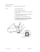
Position the jeweler's flathead screwdriver behind the
small black plastic extension as shown in Figure 13,
#2. Gently pry the motor out. Note the position of the
connector and the wires on the ribbon motor
assembly.
Replace 1.
Slide the ribbon motor into position (Figure 13).
2.
Replace the two screws that hold the motor in place
(Figure 13, #1).
3. Replace the ribbon wire and the ribbon assembly.
4.
Perform the self-test.
ImageWriter II rev. Aug 87 Take-Apart / 2.21