
Owner`s manual


5.
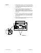
Place the frame into the plastic portion of the bottom
cover, being careful to feed the cables between the
left side of the frame and the left side of the bottom
cover. The cables attached to the bottom right side of
the frame, those that come from the SheetFeeder
connector, and the large gray ribbon cable should be
fed straight back into the opening for the metal portion
of the bottom cover (yet to be replaced).
Note:
If you have an early-model printer, connect at
this time, at the right front of the printer, the cable that
runs to the inside of the right leg and the extension
cable that connects to the cable that comes from the
transformer.
ILLUSTRATION NOT AVAILABLE
FIGURE 53
6.
Replace the two large screws (Figure 53, #1) that hold
the frame to the plastic portion of the bottom cover.
7.
If the screw exists (it doesn't on earlier models),
replace the frame screw (Figure 53, #2) between the
stepper motor and carrier motor housing.
ImageWriter II rev. Aug 91 Take-Apart / 2.65