Apple Technician Guide Mac mini (Mid 2010) Mac mini (Mid 2010) and Mac mini Server (Mid 2010) Updated 2010- 8- 3
Apple Inc. © 2010 Apple Inc. All rights reserved. Under the copyright laws, this document may not be copied, in whole or in part, without the written consent of Apple. Every effort has been made to ensure that the information in this document is accurate. Apple is not responsible for printing or clerical errors. Apple 1 Infinite Loop Cupertino, CA 95014-2084 USA + 1 408 996 1010 www.apple.com Apple, the Apple logo, Mac, and Macintosh are trademarks of Apple Inc., registered in the U.S.
Mac mini (Mid 2010) Contents About This Guide Manual Updates 7 Update 3 August 2010 7 Apple Technician Guide introduced 15 June 2010 Feedback 7 Basics Overview 9 Identifying Features 10 Product Configurations 10 Service Part Configurations 11 System Serial Number Location 11 Troubleshooting General Troubleshooting 13 Update System Software 13 Apple Diagnostics 13 Troubleshooting Theory 13 Hardware vs.
Communications 37 AirPort/Bluetooth Issues 37 Ethernet Port/Device Issue 41 Wireless Input Device Doesn’t Pair 43 Display 47 No Video 47 Uncategorized Symptom 50 Mass Storage 51 Hard Drive(s) Not Recognized 51 Hard Drive Read/Write Error 53 Hard Drive Noisy 54 Optical Drive Won’t Accept/Eject Media 59 Optical Drive Not Performing to Specifications Optical Drive Noisy 63 Uncategorized Symptoms 65 Input/Output Devices 62 66 Apple Remote Inoperable 66 Audio: Built-in Speaker Has Distorted Sound 67 Au
Bottom Cover 100 Removal 101 Reassembly 102 Memory 103 Fan 106 Reassembly Cowling 108 109 Reassembly 110 Antenna Plate 111 Reassembly Logic Board 113 115 Removal 116 Reassembly 122 AirPort/Bluetooth Combo Card Speaker Battery 126 129 Hard Drive 131 Removal 132 Reassembly 133 Power Supply 134 Reassembly 137 Optical Drive / Hard Drive (Server) 138 IR Board and Cable 141 Reassembly Housing 142 144 Views Exploded View 146 Exploded View (Server) 147 Screw Chart 148 External Vie
Apple Technician Guide About This Guide Mac mini (Mid 2010) Mac mini (Mid 2010) and Mac mini Server (Mid 2010) © 2010 Apple Inc. All rights reserved.
Manual Updates Update 3 August 2010 Take Apart: • Added information and replacement procedures for thermal sensors to the General Information, Hard Drive, Optical Drive and Views chapters. • Added additional graphic to Memory chapter showing a pulling action with fingers to verify fully seated memory.
Apple Technician Guide Basics Mac mini (Mid 2010) Mac mini (Mid 2010) and Mac mini Server (Mid 2010) © 2010 Apple Inc. All rights reserved.
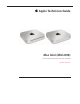
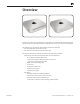
Overview Introducing the Mac mini (Mid 2010) with a completely new slimline aluminum housing design, HDMI port, SD card slot, integrated power supply, and easy access to memory and internal parts. This manual covers the two Mac mini products developed in Mid 2010: • Mac mini (Mid 2010), shown above on left • Mac mini Server (Mid 2010), shown above on right The Mac mini (Mid 2010) is a follow-on product to the Mac mini (Late 2009).
Identifying Features The Mac mini (Mid 2010) computer features include: • Low-profile housing design • Service access is through the bottom cover, which is removed without tools. • HDMI port • SD card slot • 4 USB ports • Internal power supply • Increased processor speeds: -- 2.4 GHz Dual-Core -- 2.
Service Part Configurations • Logic board assembly removal requires a special tool: -- Logic board removal tool (922-9588) • Although the thermal sensor on the flex cable of the top hard drive can be replaced by replacing the flex cable, the other thermal sensors on the hard drives or optical drive are not replaceable. To replace the sensor, a replacement drive must be ordered.
Apple Technician Guide Troubleshooting Mac mini (Mid 2010) Mac mini (Mid 2010) and Mac mini Server (Mid 2010) © 2010 Apple Inc. All rights reserved.
General Troubleshooting Update System Software Important: Whenever possible before beginning troubleshooting, ensure the latest software and firmware updates have been applied. Firmware is the name given to software that is written into memory circuits such as flash memory, that will hold the software code indefinitely, even when power is removed from the hardware.
Common Reset Procedures When a reset procedure is required for troubleshooting, follow the applicable steps: Resetting the System Management Controller (SMC) To reset power management via the SMC chip: 1. Unplug all cables from computer, including power cord. 2. Wait at least 15 seconds. The SMC reset occurs automatically once the Mac mini has been unplugged from AC power source for several seconds. 3. Plug power cord back in, making sure power button is not being pressed. 4.
Starting Up in Safe Mode A Safe Boot is a special way to start Mac OS X when troubleshooting. To start up into Safe Mode (Safe Boot), 1. Make sure the computer is shut down. 2. Press the power button. 3. Immediately after you hear the startup tone, press and hold the Shift key. Note: The Shift key should be held as soon as possible after the startup tone but not before. 4. Release the Shift key when you see the screen with the gray Apple and progress indicator (looks like a spinning gear).
Block Diagram Refer to this diagram to see how modules are interrelated.
2010-08-03 Connector locations, and the possible symptoms when cable is disconnected, mis-connected or shorted.
Symptom Charts Follow the steps in the order indicated below. If an action resolves the issue, retest the system to verify. Note: A compilation of Quick Check tables is available at: http://service.info.apple.com/QRS/en/quickreference.pdf Startup and Power No Power, Dead Unit Unlikely cause: speakers Quick Check 2010-08-03 Symptoms Quick Check No Power, Dead Unit • No power • No LED • No fan spin • No startup chime • No image on external display • No hard drive or optical drive activity 1.
Deep Dive Unlikely cause: speakers Check 2010-08-03 Result Action 1. Connect AC to computer and press the power button on system. Verify if there is any indication that the system has powered up (fan rotation, hard drive or optical drive noise, ...). Yes The system is powering up. Jump to Won’t Start Up symptom flow. No Go to step 2. 2. Reseat the installed SDRAM memory module(s) and retest. Does the computer start up properly now? Yes Badly seated SDRAM memory module.
10-08-03 6. Disconnect power button connector from logic board and short the two power button connector pins on logic board. Verify if the unit powers on. Yes Replace Power Button assembly X03 No Go to step 7 7. Disconnect AirPort/Bluetooth card, Hard Drive, Optical Drive and LED/IR Sensor cables from logic board. Connect AC cable and press the power button to verify if a startup error tone is heard. Yes Reconnect one by one each device and retest to identify the shorting one.
Won’t Start Up Quick Check Symptoms Quick Check Won’t Start Up • No startup chime • Error tones during startup. • Grey screen with fan noise, or other noise. • Will not progress beyond Apple logo or spinning gear. 1.
Deep Dive Check Result Action 1. Insert Mac mini Install DVD in optical drive (or in the optical drive of another computer set up in FireWire Target Disk Mode) and boot the computer with the D keyboard key pressed to run Apple Hardware Test. Does the computer boot up to this volume? Yes Run the extended tests and proceed with results. If AHT passes or boots with a memory error, go to step 2. No Go to step 2. 2. Remove the installed SDRAM, and test with known-good SDRAM.
5. Power on system, press the C key on keyboard , insert the original Mac mini 10.6.X Install DVD in internal optical drive (or in the optical drive of another computer set up in FireWire Target Disk Mode) and attempt to boot from it. Does it boot? Yes Reconnect the hard drive cable to logic board and go to step 6 No If the optical drive is not recognized, go to Optical Drive not recognized. 6. Power on system, press the Alt key on keyboard and attempt to boot the system from the Internal hard drive.
Intermittent Shutdown Unlikely cause: hard drive, optical drive Troubleshooting Shutdown Causes Always run the latest available service utilities, to look for the possible cause of a previous shutdown. These utilities will permit to isolate any abnormal value readings from the thermal, voltage, or current sensor(s), and from the fan(s) speed meter(s). Collect all available info from user on shut down occurrence details: periodicity, connected devices, running applications, running time before shutdown.
- one of the current sensors reached a specified current limit, These shut downs are due to temperature, voltage, current, fan speed or other hardware related sensor values getting out of range, so the suggested steps for troubleshooting will be: - to check for all sensors connections and values using the latest available service utilities and Apple Service Diagnostics, - to check for fan(s) operation, - to check for cleanliness of the heatsink fins and the air flows, - to check for correct seating of the h
2. Activity related shutdowns: Reset SMC and PRAM and verify that shutdown issue still happens. Yes Check with booting from known-good bootable drive: go to step 3 No Shutdown cause was related to SMC or Pram programmed shutdown settings or corruption, and was resolved by reverting them to default settings. 3. Boot from a known-good bootable drive (external bootable drive or similar system set as FireWire Target mode) , verify that shutdown issue still happens.
5. Verify if a thermal sensor or fan failure is reported by latest available service diagnostics. Yes - If a fan failure is reported, check for fan cable seating and retest. If same failure happens when retesting, replace fan with known-good one and retest. If issue does not happen anymore with the known-good fan, replace user’s fan. - If a thermal failure is reported, check for cause of excessive temperature, (like clogged fan, disconnected sensor cable, obstructed vent, dust in heatsink fin) and retest.
Kernel Panic, System Crashes Quick Check Symptoms Quick Check Kernel Panic, System Crashes • Kernel Panic on startup or desktop use. • System freeze during use. • System freeze upon wake from sleep. 1. Isolate OS by starting up system from original Mac mini Install DVD, from the same model of computer setup in Target Disk Mode, or from compatible known-good OS on an external drive. Both AirPort and Bluetooth services are available when booted from the Install disk. 2.
2. Remove all external peripheral devices including keyboard and mouse. Does computer now start without any kernel panic? Yes Add peripheral devices one at a time and restart each time until the kernel panic repeats. Replace device whose addition causes the issue. No Go to step 3. Yes Install user’s SDRAM and test. If kernel panic repeats, replace SDRAM. Verify that the correct SDRAM type is being used. No Go to step 4. 4.
No Video Unlikely cause: hard drive, optical drive, speakers Quick Check Symptoms Quick Check No Video • No image. 1. Inquire which video port and cable is used by customer. 2. Check connectors and cables for pin damage. 3. Check both computer DisplayPort and HDMI connections with known-good displays. 4. (DisplayPort) If DisplayPort to DVI adapter cable is used in customer’s configuration, check it on a known-good computer 5.
3. (HDMI) Connect supported known-good external display on HDMI port. Select HDMI input on display and verify whether image appears correctly on external display when system is booted. Yes Video circuitry on logic board functional. Return to customer or jump to appropriate display issue troubleshooting flow. No Go to step 4 4. Replace with known-good SDRAM and verify that the computer displays video. Yes Install user’s SDRAM and test. If no video issue reoccurs, replace SDRAM.
Check Action 1. Boot from Original Mac mini Install DVD inserted in internal optical drive (or in optical drive of another computer setup in Target Disk Mode), and verify whether issue is still visible. Yes Go to step 2. No Issue likely caused by installed software or driver issue. Troubleshoot for software issues. Make sure all software updates have been installed. 2. Use known-good SDRAM in the system. Does the corrupted video issue still appears? Yes Go to step 3.
Burnt Smell/Odor Unlikely cause: speakers, microphone, housing Quick Check Symptoms Quick Check Burnt Smell/Odor • Burning smell • Unusual odor 1. Verify source of smell/odor is emanating from the system. 2. Refer to KBase articles: http://support.apple.com/kb/TA22044 or http://support.apple.com/kb/TA22045. 3. Disconnect all third party devices and confirm whether the odor is being generated by the device. 4. Inspect air intake and air outlets for obstructions.
3. Can the source of the odor be located using nose? Yes Replace affected module(s) and retest system. No Contact Apple for assistance if you feel that there is a possible safety issue with the computer that has not been resolved in the previous steps. P08 Noise, Hum, Vibration Unlikely cause: enclosure, cables. Quick Check Symptoms Quick Check Noise/Hum/Vibration • Buzzing noise • Rattling noise • Ticking noise • Squeaking 1.
Deep Dive Check 1. Run latest available service diagnostics. Was an error reported? Action Yes Suspect possible fan or sensor error. Check fan cable connection to the logic board. No Go to step 2. Yes Reset SMC by disconnecting power cord for ~15 seconds then retest. If issue persists go to step 3. No Go to step 5. Yes Suspect issue with optical drive or media being used. Jump to ‘Optical Drive Noisy’ symptom flow. No Go to step 4. 4. Mute the system volume.
7. Remove bottom cover, disconnect AirPort antenna and remove shield, disconnect and remove Fan and cowling, then disconnect one at a time each following cable and retest :HDD, ODD/HDD, then power ON the system each time . Determine if noise issue goes away when one of these modules is disconnected. Note: Do not keep system On for long, when fan is disconnected. Yes Identify, inspect, and if necessary, replace the part that caused the noise until it was disconnected from the system.
Communications AirPort/Bluetooth Issues Quick Check Symptoms Quick Check AirPort/Bluetooth Issues • AirPort or Bluetooth cannot be enabled. • AirPort/Bluetooth card not available in System Profiler • Unable to join networks or pair devices • Intermittent device or connection dropouts • Limited wireless range 1. Verify that AirPort or Bluetooth is turned ON , 2. (AirPort) Make sure that a network is available and selected. 3.
Deep Dive Check 1. Open System Profiler. AirPort is listed under Network, while Bluetooth is listed under USB. Are AirPort and Bluetooth ports recognized? 2010-08-03 Result Action Yes Install all available software updates for AirPort/Bluetooth and go to step 4. No Remove the AirPort/Bluetooth card and examine card and logic board connectors for damage: -If no damage is found, reseat cable on logic board and on AirPort/Bluetooth card ends and retest.
5. (AirPort) Create a Computer to Computer network with another known-good Mac computer using AirPort. See article http://docs. info.apple.com/article. html?path=AirPort/5.0/en/ ap2110.html. Can you connect to this computer successfully? 2010-08-03 Yes Network or channel issue. Go to step 7 No Double check any password required. Try connecting another known-good computer to the created network. If known-good test computer connects, replace the round AirPort antenna assembly and go to step 7 6.
AirPort/Bluetooth Card Kernel Panic Quick Check Symptoms Quick Check AirPort/Bluetooth Card Kernel Panic • Kernel Panic on startup • Kernel Panic or freezing while attempting to connect to Wi-Fi networks • Kernel Panic while transferring data on Wi-Fi networks 1. Isolate OS by starting up from original Install media for the computer, from same model computer setup in Target Disk Mode, or from compatible known good up-to date Mac OS X 10.6/X loaded on an external drive.
Ethernet Port/Device Issue Unlikely cause: Adapter, hard drive, optical drive, fan Quick Check Symptoms Quick Check Ethernet Port/Device Issue • No Ethernet device present • Unable to access network resources • Ethernet device shows no connection • Ethernet device unable to an IP address • Slow network performance 1. Check the Ethernet cable for damage, try a known good Ethernet cable – CAT5 or better recommended for 100Mbps+ connections. 2.
3. Connect the computer to another Macintosh computer using CAT5 Ethernet cable. See article . Yes Ethernet communication good. Go to step 4 No If same Ethernet cable and computer connects to a known good computer of same make and model, replace logic board 4. Check for speed and duplex issues on the network. Open System Preference > Network; click the Advanced button, then the Ethernet tab.
Wireless Input Device Doesn’t Pair Quick Check Symptoms Quick Check Wireless Input Device Doesn’t Pair • Can’t get system to recognize a Bluetooth keyboard or mouse 1. Remove and reinstall the batteries for the device. 2. Check that device is powering on. 3. Use known-good batteries with the device. 4. Ensure that device is being used within range. 30 ft. for Bluetooth devices. 5. Ensure that the latest Software Updates have been applied. Deep Dive Check 2010-08-03 Result Action 1.
4. With the known-good wireless mouse paired, does the mouse stay connected? 5. With the wireless mouse paired, does the mouse stay connected? Yes Issue resolved No Inspect and reseat the Bluetooth antenna cable on the AirPort/Bluetooth card. Replace any damaged AirPort/Bluetooth card if its antenna connector is damaged, or logic board if the Bluetooth antenna is damaged (Bluetooth antenna is part of logic board I/O wall) Go to step 5 Yes Antenna issue. Issue resolved.
Deep Dive Check 2010-08-03 Result Action 1. Open System Preferences > Bluetooth. Paired items and their connection status are shown. Is the device listed? Yes Device has been paired. Go to step 2 No The device is not paired. Make device discoverable and open Bluetooth Setup Assistant. Go to step 3 2. Make sure device is on. In System Preferences > Bluetooth, select the device and from the Action menu choose “Connect”.
8. Is the device performing to stated specifications? Yes Educate User. Issue resolved. No Replace device. Uncategorized Symptoms Quick Check Symptoms Quick Check Uncategorized Symptoms • Unable to locate appropriate symptom code. 1. Verify System Preferences/Network settings are configured appropriately to support communication method. 2. For Ethernet connection issues verify that the cable being used functions when used with another known good system. 3.
Display No Video Unlikely cause: hard drive, optical drive, speakers Quick Check Symptoms Quick Check No Video • No image. 1. Check display DisplayPort or HDMI connections 2. Connect known-good display and cables, 3. For HDMI display, power on the display first and set AV input to HDMI, then power on the Mac mini. 4. Check that customer display is directly connected to computer with known-good cables. 5. Check connections for pin damage. 6. Reset PRAM. 7. Reset SMC. 8. Go to Deep Dive.
4. Install known-good SDRAM in the system. Does the computer start with video? 5. Take apart system to access, remove battery, check battery voltage , reinstall good backup battery and retest. Does the computer start with video? Yes Install user’s SDRAM and test. If no video issue persist, replace user’s SDRAM. Verify that the correct SDRAM type is being used. No Go to step 5 Yes Issue solved. Corrupted power management or depleted backup battery caused the issue. Return system to customer.
Deep Dive Check Action 1. Boot from Original Mac mini Install DVD and verify whether issue is still visible. Yes Go to step 2. No Issue likely caused by installed software or driver issue. Troubleshoot for software issues. Make sure all software updates have been installed. 2. Use known-good SDRAM in the system. Does the corrupted video issue still appears? Yes Go to step 3. No Reinstall user’s SDRAM and test. If corrupted video issue repeats, replace SDRAM.
Uncategorized Symptom Quick Check Symptom Quick Check Uncategorized Symptom Verify whether existing symptom code applies to the issue reported by the user. If not, document reported symptom and send feedback to smfeedback@apple. com stating that a suitable symptom code could not be found.
Mass Storage Hard Drive(s) Not Recognized Unlikely cause: power supply, wireless card, fan, speaker Quick Check Symptoms Quick Check Drive Is Not Recognized Drive Does Not Boot • Flashing Question Mark • Boots to Grey Screen • Boots to Blue Screen 1. Use a known good mouse. A stuck mouse button will not allow boot. 2.
2010-08-03 3. Reboot computer. Verify that system boots successfully and rerun Disk utility ‘Verify’ function to verify that it reports no errors. Yes Data error Issue resolved. Return computer to user. H07 No Go to step 4. 4. Erase disk and reinstall Mac OS using original Mac mini Install DVD. Verify that installation process completes. Note: Make sure data has been backed up before erasing hard drive. Yes Go to step 9 No Go to step 5 5.
Hard Drive Read/Write Error Unlikely cause: power supply, wireless card, fan, speaker Quick Check Symptoms Quick Check Drive Read/Write Error Drive Bad Sector/Defective Drive Formatting Issues • Cannot save documents • Read/write error message • Hang when accessing or saving data 1. Boot from Install DVD inserted in internal optical drive (or in the optical drive of another computer setup in Target Disk Mode), or from an external bootable drive. Verify S.M.A.R.T. status of drive using Disk Utility. 2.
5. After cable was reseated, verify that system boots successfully to hard drive, and that Disk utility ‘Verify’ function reports no errors. Yes Issue resolved by cable reseat. No Replace hard drive cable and go to step 6. 6. After hard drive cable was replaced, verify that system boots successfully to hard drive, and that Disk utility ‘Verify’ function reports no errors. Yes Issue resolved by cable replacement. No Remove user’s hard drive and install a known good up to date Mac OS X 10.
Deep Dive Check 2010-08-03 Result Action 1. Disconnect hard drive and optical drive (or second hard drive) cables from logic board, and startup computer to determine if noise is caused by the computer fan. Yes Go to Fan Failures/Thermal issues symptom flow. No Go to step 2 2. If an optical drive is present, reconnect optical drive cable to logic board, insert the Mac mini Install DVD in optical drive and startup computer to verify if noise is caused by optical drive.
7. With replacement hard drive installed verify whether noise level is noticeably quieter than customer’s hard drive. Yes Customer‘s drive appears noisy: Replace customer’s hard drive and return system to customer. No Customer hard drive noise level is similar to a knowngood one and does not require repair. Reinstall user’s hard drive and return system to customer. H06 Uncategorized Symptom- Hard Drive Quick Check Symptoms Quick Check Uncategorized Symptom • Unable to locate appropriate symptom 1.
Deep Dive-Hard Drive Uncategorized Symptoms Check 1. Verify whether an existing symptom chart applies to the issue reported by the customer. Result Action Yes Jump to appropriate symptom chart flow. No Document failure symptom and send feedback to smfeedback@apple stating that a suitable symptom code could not be found.
2010-08-03 2. Test both CD and DVD media. Verify that optical drive can read both types of CD media and DVD media. Yes Go to step 6 No Drive has a laser issue. Replace the optical drive and retest 3. Remove bottom cover, disconnect AirPort antenna and remove shield, disconnect and remove fan and cowling, then reseat the optical drive flex cable on logic board and optical drive ends.
Optical Drive Won’t Accept/Eject Media Quick Check Symptoms Quick Check Drive Won’t Accept Media Drive Won’t Eject Media • Cannot insert a disc into the drive • Cannot eject a disc placed into the drive 1. Use Apple System Profiler Serial-ATA section to see if the optical drive appears. If not see Optical Drive not recognized. 2. Restart computer and hold down mouse button or keyboard eject key to cycle optical drive. 3.
4. With known good optical drive installed, test for media inject/ eject. Verify drive accepts and ejects known-good media. Yes Known-good optical drive resolved issue Replace user’s optical drive: -for an inject issue, -for an eject issue. No Optical drive cable verified or replaced, optical drive verified or replaced. Replace logic board and retest. 5. Inspect optical drive slot during disc insert/ eject. Verify that discs can be inserted easily. Yes Go to step 6 No Replace damaged optical drive.
Deep Dive Check 2010-08-03 Result Action Code 1. Verify if media is free to spin without optical drive scraping edge or surface of media? Yes Go to step 2 No Check drive correct geometry while installed. Replace optical drive 2. Test both CD and DVD media. Can drive read both CD media and DVD media? Yes Go to step 6 No Drive has a laser issue if only one media is read. Replace the optical drive. If both types media fail, go to step 3 3.
6. Test write data to compatible CD and DVD media. Verify burned media is recognized and reads reliably. Yes Issue resolved. No Issue may be media -related. Check other sources of media on computer, and check suspected media on other similar Mac mini model. Optical Drive Not Performing to Specifications Quick Check Symptoms Quick Check Optical Drive Not Performing to Specifications • Read or write speeds slower than expected 1.
2. Remove bottom cover, disconnect AirPort antenna and remove shield, disconnect and remove fan and cowling, then check the optical drive flex cable on logic board. Visually inspect connectors for any debris, damage or bent pins. If no damage, reseat optical drive flex cable on logic board, reinsert logic board and verify that both types of media are read reliably now. Yes Go to step 5 No Go to step 3 3. Connect known good optical drive and cable to logic board.
Deep Dive Check 2010-08-03 Result Action 1. Optical drive should perform a single reset sequence. Is optical drive constantly seeking or cycling eject mechanism without an optical disc installed?? Yes Drive mechanism damaged. Replace optical drive. No Go to step 2 2. Verify media does not exceed maximum thickness specification
Uncategorized Symptoms Check 1. Verify whether existing symptom code applies to the issue reported by the user. 2010-08-03 Result Action Yes Jump to appropriate symptom code flow. No Document reported failure and send feedback to smfeedback@apple.com stating that a suitable symptom code wasn’t found. Provide as much detail as possible.
Input/Output Devices Apple Remote Inoperable Unlikely cause: power supply, fan, optical drive, hard drive Quick Check Symptoms Quick Check Apple Remote Inoperable • Apple Remote doesn’t bring up Front Row • Apple Remote doesn’t control iTunes • Apple Remote doesn’t control computer volume 1. Make sure you’re using the Apple Remote within 30 feet of the computer, and have an unobstructed line-of-sight to the computer. 2.
4. Open the Apple System Profiler. Selecting USB, do you see “IR Receiver” listed? 5. Remove bottom cover, disconnect AirPort antenna and remove shield, disconnect and remove fan and cowling, then disconnect IR/LED sensor cable and connect a knowngood sensor assembly to logic board to verify that IR sensor functionality is restored. Yes IR Receiver reporting on USB bus. Check for IR cable. Go to step 5 No Remove bottom cover, and fan, and reseat the IR sensor connection to logic board.
Deep Dive Check Result Action Code 1. Launch System Preferences and select Sound/Output options. Set speaker balance to the middle, then play a sound file. Verify that sound is generated by the speaker and that the sound quality is acceptable. Yes Speaker and amplifier circuitry OK. Go to step 3. No Distortion detected in speaker. Go to step 2 2. Connect external speakers or headphones to Headphone Out port then play a sound file. Verify that sound quality is acceptable. Yes Suspect bad speaker.
Deep Dive Check 2010-08-03 Result Action 1. Verify whether boot chime is present when system is powered ON. Note: make sure audio output preferences are not set to mute and volume is set to mid-range. Yes Go to step 2 No Insert headphones into audio out jack and retest. If issue persists, replace logic board 2. Launch System Preferences and select Sound/Output options. Set speaker balance to the middle, then play a sound file.
Audio: No Audio through HDMI or Mini DisplayPort connection. Quick Check Symptoms Quick Check Audio: No audio through HDMI or DisplayPort connection. • No audio from external display speaker. 1. Reset PRAM. 2. Connect a known-good HDMI/Mini DiplayPort display and cables, Power on the display first then power on the Mac mini. Launch System Preferences and select Sound/Output options. Verify that the HDMI /DisplayPort audio sound output option is available and selected. 3.
2. Insert headphones jack into audio out jack , them remove it and verify that external display audio out port becomes available in System preferences Sound Output, and sound can be played on the external display speakers. Yes Issue no longer present. Return system to customer. No Go to step 3. 3.
Deep Dive Check 2010-08-03 Result Action 1. Unplug all FireWire devices from the computer. Start the computer and reset PRAM. Reconnect the FireWire device in question. Is the FireWire device recognized? Yes Issue resolved No Possible logic board failure. Go to step 2 2. Use a known good FireWire cable with a known good FireWire device (another Mac in FireWire Target Disk mode is good).
SD (Secure Digital) Memory Card Will Not Insert Into Slot Unlikely cause: Optical drive, hard drive, power supply Quick Check Symptom Quick Check SD Memory Card will not insert into SD Slot 1. The SD memory card must be a 32 mm by 24 mm by 2.1 mm. You can also use thinner cards, such as MultiMediaCards (MMC). SD Memory Card does not fully seat into the slot 2. Clear any obstruction in the slot. Card slot does not align with enclosure. Deep Dive 2010-08-03 Check Result Action 1.
SD (Secure Digital) Memory Card Not Recognized By System Unlikely cause: optical drive, hard drive, power supply Quick Check Symptom Quick Check SD Memory Card is not recognized by the system. 1. Insert customer’s SD card into a known-good system and verify that it functions properly. If the card cannot be read, contact the manufacturer for support options. Card does not show up on the desktop or in System Profiler 2. Verify with known-good SD Memory card that issue remains. 3.
2010-08-03 5. Check that all system software have been applied before insert a known-good unlocked SDHC Memory card and verify that it can now be correctly read and written on system. Yes Go to step 6 No Replace Logic board. 6. Retry with customer’s SD card and verify that it can now be correctly read and written on system Yes Issue fixed by software update. Go to step 7. No Only customer’s SD card is not functioning properly. Contact vendor for support options. 7.
USB Devices Not Recognized Quick Check Symptoms Quick Check USB Devices Not Recognized • USB wired keyboard/mouse not recognized • USB external drive not recognized • USB printer not recognized 1. For printers and external USB drives, make sure any external power source is plugged in and operating to isolate a power issue with the device. 2. The system has 4 USB ports on the rear of the computer. Make sure to try each port to isolate a particular port malfunction. 3.
3. Are known good mouse and keyboard recognized? 2010-08-03 Yes Test original mouse and keyboard. Replace if still not recognized. Go to step 5 No External USB ports not functioning. Replace logic board. 4. With no USB devices connected, restart the computer. Did Bluetooth Mouse Setup assistant launch after startup? Yes Bluetooth detected via Internal USB. Go to step 3 No Bluetooth not recognized via internal USB. Internal and external USB not functioning. Replace logic board. 5.
Wired Keyboard Does Not Function Properly Quick Check Symptoms Quick Check Wired Keyboard Does Not Function Properly • Some or all keys on the keyboard don’t work • Eject key or Caps Lock key doesn’t seem to work • Some keys don’t work as expected 1. The system has 4 USB ports on the rear of the computer. Make sure to try each port to isolate a particular port malfunction. 2. Test with a known good wired keyboard to isolate a failed peripheral issue. 3. Test the keyboard on another Mac.
5. With optical media in the drive, hold the Media Eject key. Does the disc eject normally and the eject symbol appear? Yes Media eject key delay. No repair necessary. No Go to Optical Drive Won’t Accept/Reject Media 6. Open System Preferences > Universal Access > Keyboard. Is “Slow Keys” enabled? Yes With “Slow Keys” on, you need to press a key for a longer period of time for it to be recognized. No Go to step 7 Yes With “Mouse Keys” on, you cannot use the Numeric Keypad to enter numbers.
Keyboard: Specific Keys Do Not Respond Quick Check Symptoms Quick Check Keyboard: Specific Keys Do Not Respond • One or more keys do not respond when pressed • Key sticks • Keycap missing 1. If wireless keyboard is being used verify that it is properly paired with the system. Go to ‘Wireless Input Device Doesn’t Pair’ symptom flow to resolve pairing issues. 2. The caps lock key has a built-in delay to reduce accidental activation and must be held for approximately ½ second for it to be activated.
Deep Dive Check Result 1. Does the computer recognize the keyboard or mouse when plugged into the USB ports? Yes Test in all USB ports to ensure all USB ports working as expected. Replace logic board for any rear port failures. Replace keyboard for any keyboard USB port failures. Go to step 2 No Go to USB Port Doesn’t Recognize Devices symptom 2. Is keyboard working as expected? Yes Go to step 3 No Go to Wired Keyboard Does Not Work Properly symptom 3.
Uncategorized Symptoms Quick Check Symptoms Quick Check Uncategorized Symptoms • Unable to locate appropriate symptom code. 1. Verify that external I/O device (where applicable) works on another system. 2. For third party I/O devices make sure necessary software is installed and up to date, and that the device is supported with the user’s system. 3. Go to Deep Dive. Deep Dive Check Result 1. Verify whether existing symptom code applies to the issue reported by the user.
Mechanical Noise/Hum/Vibration Quick Check Symptoms Quick Check Noise/Hum/Vibration • Buzzing noise • Rattling noise • Ticking noise • Squeaking noise 1. Verify that the vents on the bottom system are free of dust and other obstructions that might inhibit proper airflow through the system. . 2. Launch Applications/Utilities/Activity Monitor. Determine whether an application or process is consuming a high percentage of CPU bandwidth.
Deep Dive Check Action 1. Run latest available service utilities to check the thermal sensors and fan functional states. Was an error generated? Yes Check fan connection to logic board and retest. No Go to step 2. 2. Does noise sound like fan is running faster than expected? Yes Reset SMC by disconnecting power cord for ~15 seconds then retest. If issue continues go to step 3. No Go to step 5. Yes Suspect issue with optical drive or the media being used.
System Runs Hot Quick Check Symptoms Quick Check System Runs Hot • System feels very hot • Fan not operating • Fan running fast • System is noisy 1. Verify that the vents on the bottom are free of dust and other obstructions that might inhibit proper airflow through the system. 2. Verify that the computer is not exposed to direct sunlight which may heat up the enclosure making it feel hot to the touch. 3. Verify the computer is not running hotter than expected for normal operation. 4.
4. With replaced fan verify temperature issue is gone. Yes Issue resolved No Go to step 5. 5. Using latest service utilities, verify that all thermal sensors have correct values. Yes Issue resolved No -If a TG0H heatsink sensor is reported failing, reseat the sensor cable on logic board.
Uncategorized Symptoms Check 1. Verify whether existing symptom code applies to the issue reported by the user. 2010-08-03 Result Action Yes Jump to appropriate symptom code flow. No Document reported failure and send feedback to smfeedback@apple.com stating that a suitable symptom code wasn’t found. Provide as much detail as possible.
Service Source Take Apart Mac mini (Mid 2010) Mac mini (Mid 2010) and Mac mini Server (Mid 2010) © 2010 Apple Inc. All rights reserved.
General Information Tools The following tools are required to service the computer: • ESD wriststrap and mat • Torx T6, magnetized • Torx T8, magnetized • Torx T9, magnetized • Hex 2mm (or 5/64-inch) wrench • #0 Phillips screwdriver • Logic board removal tool (922-9588) Important: This is a required tool to service the Mac mini (Mid 2010) • Tweezers (optional) • Black stick (922-5065), or other non-conductive nylon or plastic tool • Soft cloth (to protect removed parts from scratches) • Isopropyl alcohol an
Connector Types on Logic Board The Mac mini (Mid 2010) has many small and delicate cable connectors and screws. Use extra care and finesse to avoid damaging components. Vertical Insertion (JST) • • • • • On the logic board are two types of connectors, each requiring special handling. Make sure you read these tips before disconnecting and installing the connectors. Important: These connectors are extremely fragile. Use extreme care. Major repairs may be needed if damaged.
Thermal Sensor Replacement If a replaceable thermal sensor is damaged or defective, follow the procedures below to replace. There are three locations where thermal sensors are replaceable separately. • the top hard drive flex cable (this sensor is referred to as “Ambient”) • the corner of the top hard drive • the bottom drive (either an optical, or a server hard drive) Notes: • The sensors are the same except for cable length. Make sure to use the correct sensor for the location.
Top hard drive thermal sensor (at corner) (076-1369): 1. Remove the adhesive cover and attach the sensor pad to the location shown. 2. Guide the cable around the corner of the hard drive and secure with tape, as shown.
3. Secure the sensor with tape and fold around corner. 4. The finished installation should look like this.
Top hard drive ambient thermal sensor (flex cable) (076-1370): (This sensor is also replaceable by replacing the flex cable, which comes with the sensor installed.) 1. Remove the adhesive cover and attach the sensor pad to the flex cable where shown below. 2. Verify the flex cable is installed on the hard drive. 3. Cut approximately a 1.5 cm length of the supplied black Kapton tape. 4.
Optical drive thermal sensor (076-1370): The thermal sensor may be replaced without removing the optical drive. 1. Remove the adhesive cover and attach the sensor pad where shown below. 2. Secure the sensor and cable with tape, as shown here.
Bottom hard drive thermal sensor (server) (076-1369): The thermal sensor may be replaced without removing the hard drive. 1. Remove the adhesive cover then attach the sensor pad and secure the cable with tape where shown below.
Logic Board EMI Fingers and Gaskets Be careful not to touch or damage the EMI fingers or gaskets on the logic board assembly, the housing opening, or on the bottom cover.
First Remove Hierarchy Some parts must be removed before others can be removed. Here is a chart of the progression of part removal. Parts above must be removed before the part below. Parts on the same level can be removed independently of others on that level.
Icon Legend The following icons are used in this chapter: Icon Meaning Warning or Caution Check mark; make sure you do this Do not touch Note About Images In This Guide Because a pre-production model was used for many of the images shown in this manual, you may notice small differences in appearance between the image pictured and the computer you are servicing. However, although the appearance may differ, the steps and sequence are the same unless noted.
Bottom Cover First Steps • • Shut down the computer. Place the computer on a clean, flat surface. Tools No tools are required for this procedure.
Removal 1 Lay the Mac mini upside down. 2 Rotate the bottom cover counterclockwise to the unlocked position. 3 Press on the cover to pop up the opposite side and remove it.
Reassembly 1 Replace the bottom cover using the aligning dots to place it in the unlocked position. 2 Rotate the cover clockwise to lock it in place.
Memory First Steps Remove: • Bottom cover Tools • Black stick (optional) 2010-08-03 Mac mini (Mid 2010) Take Apart — Memory 103
Removal Caution: The bracket clips can bend or components can break if too much force is used. 1 Gently spread the clips at the ends of the memory module just enough to let the free edge pop up. 2 Pull the module out of the slot. 3 Repeat to remove the second module, located under the first .
Installation 1 Carefully press the notched edge of the memory module into the slot while keeping the opposite edge slightly raised. 2 Pull the module into place with your fingers, as shown, to verify that it is fully seated. 3 Press down on the raised edge until the clips snap into place. 4 Repeat to install the top memory module.
Fan First Steps Remove: • Bottom cover Tools • • Torx 6 screwdriver Black stick 2010-08-03 Mac mini (Mid 2010) Take Apart — Fan 106
Removal 1 Remove 2 T6 fan screws (with bumpers) • 922-9582 • 922-9581 • 922-9572 2 Carefully lift the fan off the standoff to reveal the fan connector on the logic board. Note: You can optionally loosen all three screws and lift off the fan with the screws attached.
3 Disconnect the fan cable from connector on the logic board. Replacement Note: Make sure to connect the fan cable. Reassembly Important: The two top screws are different sizes. Make sure to use the correct size in the correct location. • 922-9582 is longer and goes on the left attaching to the heatsink • 922-9581 goes on the right, to the standoff on the logic board. Make sure to install a bumper (922-9572) to the top of these screws. 922-9582 922-9581 (& 922-9572) (& 922-9572) ~ 0.
Cowling First Steps Remove: • • Bottom cover Fan Tools • • Torx T6 screwdriver Black stick 2010-08-03 Mac mini (Mid 2010) Take Apart — Cowling 109
Removal 1 • 2 Remove the T6 screw shown: 922-9580 Lift the cowling up slightly to clear other hardware and pull straight out, rotating slightly clockwise, to disengage it. Inserting the pointed end of a black stick into the top screw hole may help to pull out the cowling. Be careful not to catch on components underneath. Note: The left side of the cowling clips onto a clip screw on the heatsink inside the housing.
Antenna Plate First Steps Remove: • • • Bottom cover Fan Cowling Tools • • • Torx T8 screwdriver 2 mm (9/64-inch) Hex wrench Black stick 2010-08-03 Mac mini (Mid 2010) Take Apart — Antenna Plate 111
Removal 1 • Remove 4 screws. (2) 922-9577 T8 • (2) 922-9574 2mm Hex 2 Carefully lift the antenna assembly up slightly and slide it to the right to reveal the antenna cable attached to the wireless card. A black stick may help to maneuver it.
Warning: The edge of the shield is sharp. Use care to avoid injury and to avoid damaging the antenna cable. 3 Disconnect the antenna cable. Reassembly 1 Connect the antenna cable. Before seating, make sure the cable is aligned in the channel, parallel with the edge of the hard drive and under the edge of the case, as shown above.
2 Slide the antenna plate into place on the housing. Note: The edge of the plate has a slot that the edge of the housing must fit into for the plate to sit flat and the screw holes to align. (see rough cross-section example at right) 3 A tool, such as the hex wrench, inserted slightly into one of the plate holes may help to maneuver. Be careful not to damage the cosmetic Mylar on the hard drive, or allow the tool to damage the housing.
Logic Board First Steps Remove: • • • • • Bottom cover RAM (at least the top level) Fan Cowling Antenna plate Tools • • • • Logic board removal tool: 922-9588 Torx T6, T8 & T9 screwdrivers 2 mm (9/64-inch) Hex wrench Black stick 2010-08-03 Mac mini (Mid 2010) Take Apart — Logic Board 115
Removal Important: The small JST connectors (C, D, E, F) are extremely fragile. Use extreme care and finesse to lift them carefully straight up and out of their sockets on the logic board. See Vertical Insertion (JST) instructions in the General Information section of the Take Apart chapter. Note: Some of these cables are not replaceable and require drive replacement if damaged. 1 Carefully disconnect the cables connected to the logic board.
2 Make sure that at least the top level of RAM has been removed. This is to avoid the potential for damaging the EMI gasket on the housing. 3 Remove 2 T6 screws: 922-9579 • • 922-9575 (if not previously removed with the fan) And 1 T9 standoff: • 922-9576 4 • Remove the 2 mm Hex screw on the housing. This is to reduce the possibility of scratching the fan channel area.
5 Insert the logic board removal tool straight down into the holes shown. Make sure that it is firmly seated to the capture holes on the bottom of the housing. Warning: Do NOT insert the removal tool, or anything else, into screw holes. This will damage the logic board by displacing the screw guides underneath. 6 Carefully push down and pull back on the tool until the I/O wall separates from the housing slightly. 7 Remove the tool. Important: Do not remove the assembly.
8 Disconnect the power cable. Wiggle it out from its logic board socket. Tweezers may be helpful. 9 Important: If thermal cables are damaged it requires replacing the optical or hard drive. Verify that all cables are disconnected from the logic board and no connectors will catch or snag when removing the assembly. 10 Push in on the catch tabs on each side of the I/O wall to release the logic board assembly and begin to slowly guide it out.
Important: When handing the logic board assembly, avoid touching EMI fingers and gaskets. Oil from your fingers can reduce connectivity and wireless performance. 11 Once the I/O wall is free, continue to carefully guide the assembly straight out of the housing. Do not force or lift. As the memory bracket approaches the housing opening, make sure the bracket clip does not catch or damage the EMI gasket at the top of the housing interior.
Important: When returning the board to Apple, make sure to include: • AirPort/Bluetooth flex cable • Speaker • Cowling clip screw • • Make sure to remove: Memory DIMMs AirPort/Bluetooth card 2010-08-03 Mac mini (Mid 2010) Take Apart — Logic Board 121
Reassembly 1 Position the housing vertically and insert the logic board assembly into the housing. This allows easier verification that all EMI gaskets and clips are entering into the housing properly. Note: If resistance is encountered, it may be where the left side of the logic board bumps against the drive carrier. Maneuver the board to clear the carrier. 2 Reconnect the power supply cable before seating the logic board assembly completely. Tweezers and a black stick may be helpful.
AirPort/Bluetooth Combo Card First Steps Remove: • • • • • Bottom cover Fan Cowling Antenna plate Logic board assembly Tools • • Torx T6 screwdriver Black stick 2010-08-03 Mac mini (Mid 2010) Take Apart — AirPort/Bluetooth Combo Card 123
Removal 1 Disconnect the two antenna cables shown. 2 Disconnect the flex cable. 3 Remove 4 screws: (3) 922-9596 • • (1) 922-9597 (through speaker) 4 If the speaker has not previously been removed, lift the AirPort/Bluetooth card slightly to clear the screw boss, then slide out from under the speaker screw tab.
5 If replacing the flex cable, use a black stick to lift its connector straight up to remove. Note: If replacing the logic board, do not remove the flex cable as it is returned with the logic board.
Speaker First Steps Remove: • • • • • Bottom cover Fan Cowling Antenna plate Logic board assembly Tools • • Torx T6 screwdriver Black stick 2010-08-03 Mac mini (Mid 2010) Take Apart — Speaker 126
Removal 1 • • Remove 2 screws: 922-9597 (this screw may have already been removed if the AirPort/Bluetooth board has been removed). 922-9598 Important: When reinstalling, make sure to install this screw at the heatsink, or damage can result. 2 Carefully lift the speaker to reveal the speaker cable connected to the logic board, and disconnect.
3 Note: Check the speaker magnet for missing screws before reassembly. Important: Do not overtighten screws. Install all screws by hand. Do not use power tools.
Battery First Steps Remove: • • • • • Bottom cover Fan Cowling Antenna plate Logic board assembly Tools • Black stick 2010-08-03 Mac mini (Mid 2010) Take Apart — Battery 129
Removal 1 Insert a black stick under the battery and push it up and out. 2 Grab the battery as it slips up and out of the battery holder.
Hard Drive First Steps Remove: • • • • • Bottom cover Fan Cowling Antenna plate Logic board assembly (partial remove) Server Note: • For the lower hard drive on the server, follow the procedures to remove the optical drive.
Removal 1 Dislodge the logic board assembly partially. (You do not need to disconnect the power supply cable.) 2 Slide out the hard drive. Thermal Sensor Note: • Thermal sensors on replacement drives are pre-installed, but are also replaceable separately. See the Thermal Sensor Replacement section. Part Note: • To install the flex cable, connect it to the hard drive, then use the included tape to secure the connector to the top of the hard drive.
Reassembly Be very careful not to damage the cosmetic Mylar cover or catch it on the edge of the housing opening. Note: The hard drive has two pins that secure it to the internal side wall of the case. 1 Slide hard drive assembly into the case. 2 Maneuver the hard drive until the pins secure to the holes in the case. . Wiggling the drive with a black stick inserted into one of the top hard drive screw holes may be helpful. The drive should not move sideways once secure.
Power Supply First Steps Remove: • • • • • • Bottom cover Fan Cowling Antenna plate Logic board assembly Hard drive Tools • • • • Torx T6 screwdriver Black stick Tweezers (optional) Power cord (optional) 2010-08-03 Mac mini (Mid 2010) Take Apart — Power Supply 134
Removal 1 Slide the power cord socket retention clip left to release the socket. 2 Rotate the power cord socket 90-degrees counterclockwise, to disengage.
3. • Remove one screw: 922-9578 4 Pull out power supply assembly, rotating slightly left.
Reassembly Notes: • The power supply has alignment pins that must fit into their recesses inside the housing. • The power cord socket rotates within groves in the housing and must be aligned straight before the retention clip can be inserted. • An unplugged power cord inserted into the socket may be helpful to straighten the socket.
Optical Drive / Hard Drive (Server) First Steps Remove: • • • • • • Bottom cover Fan Cowling Antenna plate Logic board assembly Power supply Thermal Sensor Note: • Thermal sensors on replacement drives are pre-installed, but are also replaceable separately. See the Thermal Sensor Replacement section.
Removal 1 Remove the T6 screw, 922-9578. 2 Lift the drive and carrier assembly out of the case.
3 • Remove 4 T8 screws in the drive carrier: 922-9583 Server Note: For the lower hard drive on the server, the screws are located in front and back of the carrier. • 922-9585 4 Lift the drive from the carrier. 5 If replacing the optical drive flex cable, install and align the cable carefully. Apply the straight edge of the included tape to the flex connector then fold over onto the top of the flex cable to secure to the drive.
IR Board and Cable First Steps Remove: • • • • • • Bottom cover Fan Antenna plate Logic board assembly Power supply Optical drive Tools • • Phillips #0 screwdriver Black stick 2010-08-03 Mac mini (Mid 2010) Take Apart — IR Board and Cable 141
Removal 1 Remove 1 screw 922-8820. 2 Note the IR cable routing on the drive carrier. 3 Remove the IR cable from the cable channel. Reassembly The IR board must fit over the pin on the drive carrier before securing the screw. Important: Make sure the grounding clip has not been damaged and will make contact with the case.
1 Insert the IR cable into the cable channel, as shown.
Housing First Steps • • Remove all other parts. The housing is what’s left after all other parts have been removed. Tools No tools are required for this procedure.
Service Source Views Mac mini (Mid 2010) Mac mini (Mid 2010) and Mac mini Server (Mid 2010) © 2010 Apple Inc. All rights reserved.
Exploded View Bottom Cover 922-9567 Antenna Plate 922-9564 Fan 922-9557 Screw, Cowling 922-9580 Screw, Antenna Plate to hard drive 922-9577 Fan Screw, Heatsink 922-9582 Fan Screw Bumper 922-9572 Fan Screw, Top Right 922-9581 Standoff, Fan 922-9576 Standoff, Fan, Tall 922-9575 Cowling 922-9568 Thermal Sensor Kit, ODD/Ambient, w/tape 076-1370 Hard Drive, Top, w/sensors, alignment screws, and flex cable 320 GB, SATA, 5400, 2.5-in 661-5493 500 GB, SATA, 5400, 2.
Exploded View (Server) Bottom Cover 922-9567 Antenna Plate 922-9564 Fan 922-9557 Screw, Cowling 922-9580 Screw, Antenna Plate to hard drive 922-9577 Fan Screw, Heatsink 922-9582 Fan Screw Bumper 922-9572 Fan Screw, Top Right 922-9581 Standoff, Fan 922-9576 Standoff, Fan, Tall 922-9575 Cowling 922-9568 Thermal Sensor Kit, ODD/Ambient, w/tape 076-1370 Hard Drive, Top w/sensors, alignment screws, and flex cable 500 GB, SATA, 7200, 2.
Screw Chart Note: Screws are not to scale. 922-9582 Torx T6 - Fan to heatsink (1). 922-9575 Torx T6 - Standoff, fan, tall (1) 2010-08-03 Torx T6 922-9572 - Top of fan screws (2) 922-9576 922-9580 Torx T9 - Cowling (1) 922-9574 2 mm (5/64-in.
External Views Front View A = Slot-loading optical disc drive B = Bottom cover C = Power indicator light D = Built-in infrared (IR) receiver Front View - Server A = Bottom cover C = Power indicator light D = Built-in infrared (IR) receiver 2010-08-03 Mac mini (Mid 2010) External Views 149
Port View A = Power button B = Gigabit Ethernet port (10/100/1000 Base-T) C = FireWire 800 port D = Cool air inlet (around bottom cover) E = Exhaust vent F = Audio in port G = Audio out port H = SD card slot I = USB 2.