Apple Technician Guide Mac mini (Mid 2011) Mac mini (Mid 2011) and Mac mini Server (Mid 2011) Updated 2011-07-21
Apple Inc. © 2011 Apple Inc. All rights reserved. Under the copyright laws, this document may not be copied, in whole or in part, without the written consent of Apple. Every effort has been made to ensure that the information in this document is accurate. Apple is not responsible for printing or clerical errors. Apple 1 Infinite Loop Cupertino, CA 95014-2084 USA + 1 408 996 1010 www.apple.com Apple, the Apple logo, Mac, and Macintosh are trademarks of Apple Inc., registered in the U.S.
Mac mini (Mid 2011) Contents About This Guide Manual Updates 7 Apple Technician Guide introduced 21 July 2011 7 Feedback 7 Basics Overview 9 Identifying Features 9 Product Configurations 10 Service Procedure Differences 10 Service Part Configurations 10 Thunderbolt 11 System Serial Number Location 11 Troubleshooting General Troubleshooting 13 Update System Software 13 Repairing, Restoring, or Reinstalling Mac OS X Software Diagnostics 13 Wireless Troubleshooting 13 Troubleshooting Theory 14 Hardware
Corrupted Video 35 Burnt Smell/Odor 37 Noise, Hum, Vibration 38 Communications 42 Wi-Fi/Bluetooth Issues 42 Wi-Fi/Bluetooth Card Kernel Panic 45 Ethernet Port/Device Issue 46 Bluetooth Device Doesn’t Pair 48 Bluetooth Device Loses Connection 49 Display 52 No Video 52 Corrupted Video 54 Mass Storage 57 Internal Drive(s) Not Recognized 57 Internal Drive Read/Write Error 59 Hard Drive Noisy 61 Input/Output Devices 65 Apple Remote Inoperable 65 Audio: Built-in Speaker Has Distorted Sound 66 Audio: Bu
First Remove Hierarchy 99 Icon Legend 100 Note About Images In This Guide Bottom Cover 101 Reassembly 103 100 Memory 104 Installation 106 Fan 107 Reassembly Cowling 109 110 Antenna Plate 112 Reassembly Logic Board 114 117 Reassembly 125 AirPort/Bluetooth Combo Card Reassembly Speaker Battery 128 129 132 Hard Drive (Lower Bay) Reassembly 134 137 Power Supply 139 Reassembly 142 Hard Drive (Upper Bay) Reassembly 143 145 Infrared (IR) Board and Cable Reassembly Housing 126 1
Apple Technician Guide About This Guide Mac mini (Mid 2011) Mac mini (Mid 2011) and Mac mini Server (Mid 2011) © 2011 Apple Inc. All rights reserved.
Manual Updates Apple Technician Guide introduced 21 July 2011 This manual covers the two Mac mini products released in mid 2011: • Mac mini (Mid 2011) • Mac mini Server (Mid 2011) Feedback We want your feedback to help improve this and future Technician Guides! Please email any comments to: smfeedback5@apple.
Apple Technician Guide Basics Mac mini (Mid 2011) Mac mini (Mid 2011) and Mac mini Server (Mid 2011) © 2011 Apple Inc. All rights reserved.
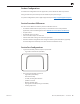
Overview This manual covers the two Mac mini products released in mid 2011: • Mac mini (Mid 2011) • Mac mini Server (Mid 2011) Identifying Features The Mac mini (Mid 2011) models continue in the slimline aluminum housing design, introduced with the previous Mac mini (Mid 2010). The Mac mini (Mid 2011) models do not have optical drive slots, so externally they look like a Mac mini Server (Mid 2010). The Mac mini (Mid 2011) can be further identified by the following external cues: • Model No.
Product Configurations To confirm the configuration from the Apple menu, choose About This Mac. The processor listing will show the speed of the processor followed by the processor type. For product configurations, refer to Apple Support Tech Specs: http://support.apple.com/specs/ Service Procedure Differences The main service differences from the previous model Mac mini are: • No software install media.
Thunderbolt Mac mini (Mid 2011) includes a new Thunderbolt port that connects Thunderbolt-compatible high-resolution displays and high-performance data devices for high-speed data transfer. Thunderbolt I/O technology sets new standards for speed, flexibility, and simplicity. Read more at http://www.apple.com/thunderbolt/ Important: Thunderbolt requires up-to-date software and firmware to function properly. Obtain the latest updates via Software Update.
Apple Technician Guide Troubleshooting Mac mini (Mid 2011) Mac mini (Mid 2011) and Mac mini Server (Mid 2011) © 2011 Apple Inc. All rights reserved.
General Troubleshooting Update System Software Important: Before you begin troubleshooting, ensure the correct version of Mac OS X is installed, and check for and apply all the latest software and firmware updates. Firmware is the name given to software that is written into memory circuits such as flash memory, that will hold the software code indefinitely, even when power is removed from the hardware.
Troubleshooting Theory For general information on troubleshooting theory, go to GSX and find the Service Training course menu link. From there you can access the Troubleshooting Theory self-paced course. Hardware vs.
Logic Board Reset - Coin Battery Test and PRAM Reset A dead battery may prevent computer from operating. Removing the coin battery for 1-2 minutes will also fully reset the logic board PRAM. 1. Shut down and unplug the computer. Allow several minutes for power supply to discharge. 2. The coin battery is located on the bottom side of the logic board and provides power for the battery-backed RAM and clock. Measure DC voltage on battery touching battery with red probe, and grounding with black probe.
Sensor Errors Run latest available service utilities to determine if any sensors or fan are malfunctioning. When a test reports an error, reseat appropriate connection. For thermal errors, first check that all air flows are free from obstruction, that fan rotor is not mechanically blocked, that fan cable connection is correctly seated on logic board, and that fan is operating when computer is powered on . If issue persists, replace the corresponding part (fan, logic board, or power supply).
2011-07-21 TM0P DIMM memory proximity thermal sensor (on logic board): Excessive memory modules temperature. Logic board. Test with known-good DIMM memory modules or/and logic board. TP0C Excessive power supply temperature (this sensor is part of power supply) Power supply. Test with known-good power supply or/and logic board. TP0P I/O controller proximity thermal sensor (on logic board): Excessive I/O controller temperature. Logic board.
2011-07-21 Backup Battery (on opposite side of logic board) : - lost date and time settings - lost configuration settings - no startup/video Mac mini ((Mid 2011) 2.5GHz Mac mini ((Mid 2011) 2.
Block Diagrams Refer to these diagrams to see how modules are interrelated Mac mini (Mid 2011) 2.3GHz Dual Core PC3-10600 SODIMM DDR3 1333 Channel-A EEP ROM Dual-channel Memory Controller 64b DDR3 1333 Channel-B PCIe x8 Mobile Sandy Bridge CPU (2 Core, 2.3 GHz) 64b PCIE PCIe x4 Thunderbolt GT2 @ 1.
Mac mini (Mid 2011) 2.5GHz Dual-Core 2.7GHz Dual-Core GDDR5 256 MB VRAM PC3-10600 SODIMM DDR3 1333 Channel-A 64b Dual-channel Memory Controller 64b DDR3 1333 Channel-B Mobile Sandy Bridge CPU ( 2 Core 2.5/2.
Mac mini Server (Mid 2011) 2.0GHz Quad-Core PC3-10600 SODIMM DDR3 1333 Channel-A EEP ROM Dual-channel Memory Controller 64b DDR3 1333 Channel-B Mobile Sandy Bridge CPU (4 Core, 2.0 GHz) 64b PCIE PCIe x4 Thunderbolt uC P2,3 GT2 @ 1.
Symptom Charts Follow the steps in the order indicated below. If an action resolves the issue, retest the system to verify. Startup and Power No Power, Dead Unit Unlikely cause: speakers Quick Check Symptoms Quick Check No Power, Dead Unit • No power • No LED • No fan spin • No startup chime • No image on external display • No hard drive activity 1. Verify power source. 2. Verify power cable. 3.
2011-07-21 3. Replace installed SDRAM memory module(s) with known-good one. Does the computer start up properly now? Yes Replace defective user’s SDRAM memory module. No Go to step 4 4. Remove bottom cover, disconnect antenna and remove shield, disconnect and remove fan and cowling, then disconnect the following cables from logic board before being able to extract it :internal drive(s) flex cable(s), IR/LED cable.
8. Disconnect the power supply cable from logic board , reconnect AC power cord and use a multimeter to verify that a 12 Volts voltage is present between the two outer pins of cable. See Apple Technical article http://support.apple. com/kb/HT3250 for details on using a digital multi-meter Yes Power supply is present. Replace logic board and retest. M01 No Replace cable between power supply and logic board and retest. If issue persists after cable was replaced, replace power supply and retest.
Deep Dive Check Result Action 1. Connect computer to Apple Service Toolkit (AST) test network, press the N keyboard key and run Mac Resource Inspector (MRI). Does the computer start from AST and successfully run MRI? Yes Go to step 3. No Go to step 2. 2. Remove the installed SDRAM, and test with known-good SDRAM. Does the computer startup properly now? Yes SDRAM issue. Replace SDRAM. Issue resolved. No Go to step 3. 3.
2011-07-21 5. Connect and try to start up from known-good original system media, like an up-todate, bootable OS X volume or similar system connected and setup in Target Disk Mode, and press the Option (alt) key on startup to select and attempt to boot from it. Does system boot from one of these devices? Yes Reconnect main drive cable to logic board and go to step 6 No If second drive is not recognized, go to SSD Drive not recognized. 6.
Intermittent Shutdown Unlikely cause: hard drive Quick Check Symptoms Quick Check Intermittent Shutdown • Powers off during startup. • Powers off during desktop use. • Computer restarts spontaneously. • Powers off when waking from sleep. 1.
Troubleshooting Shutdown Causes Always run the latest available service utilities, to look for the possible cause of a previous shutdown. These utilities will permit to isolate any abnormal value readings from the thermal, voltage, or current sensor(s), and from the fan(s) speed meter(s). Collect all available info from user on shut down occurrence details: periodicity, connected devices, running applications, running time before shutdown.
- to check for fan operation, - to check for cleanliness of the heat sink fins and the air flows, - to check for correct seating of the heat sink on logic board and presence of adequate thermal material. Deep Dive Check Result 1. Power related shutdown : Check with known-good AC cable. Verify if the shutdown issues disappear with known-good AC cable. Yes Faulty user’s AC cable. Replace user’s AC cable. No Symptoms unchanged - Go to step 2 2.
5. Verify if a thermal sensor or fan failure is reported by latest available service diagnostics. Yes - If a fan failure is reported, check for fan cable seating and retest. If same failure happens when retesting, replace fan with known-good one and retest. If issue does not happen anymore with the known-good fan, replace user’s fan.
Kernel Panic, System Crashes Quick Check Symptoms Quick Check Kernel Panic, System Crashes • Kernel Panic on startup or desktop use. • System freeze during use. • System freeze upon wake from sleep. 1.
2. Remove all external peripheral devices including keyboard and mouse. Does computer now start without any kernel panic? Yes Add peripheral devices one at a time and restart each time until the kernel panic repeats. Replace device whose addition causes the issue. No Go to step 3. Yes Install user’s SDRAM and test. If kernel panic repeats, replace SDRAM. Verify that the correct SDRAM type is being used. No Go to step 4. 4.
No Video Unlikely cause: hard drive, speakers Quick Check Symptoms Quick Check No Video • No image. 1. Inquire which video port and cable is used by customer. 2. Check connectors and cables for pin damage. 3. Check both computer Thunderbolt and HDMI connections with known-good displays. 4. (Thunderbolt) If a Mini DisplayPort to DVI adapter cable is used in customer’s configuration, check it on a known-good computer 5.
2011-07-21 3. (HDMI) Connect supported known-good external display on HDMI port. Select HDMI input on display and verify whether image appears correctly on external display when system is booted. Yes Video circuitry on logic board functional. Return to customer or jump to appropriate display issue troubleshooting flow. No Go to step 4 4. Replace with known-good SDRAM and verify that the computer displays video. Yes Install user’s SDRAM and test. If the no video issue reoccurs, replace SDRAM.
Corrupted Video Unlikely cause: Adapter, hard drive, fan, or speaker. Quick Check Symptoms Quick Check Corrupted Video • Text and graphics appear fuzzy • Image corrupted 1. Set System Preferences/Display to a native resolution. Non-native resolutions are unable to produce optimal clarity. 2. Make sure all relevant software updates have been applied. Graphics driver updates may be included with software updates. 3. When the issue occurs take a screenshot of the display (Command-Shift-3).
Deep Dive Check Action 1. Start up from a different known-good original system media or an up-to-date, bootable OS X volume. Does the corrupted video issue still appear? Yes Go to step 2. No Issue likely caused by installed software or driver issue. Troubleshoot for software issues. Make sure all software updates have been installed. 2. Use known-good SDRAM in the system. Does the corrupted video issue still appear? Yes Go to step 3. No Reinstall user’s SDRAM and test.
Burnt Smell/Odor Unlikely cause: speakers, microphone, housing Quick Check Symptoms Quick Check Burnt Smell/Odor • Burning smell • Unusual odor 1. Verify source of smell/odor is emanating from the system. 2. Refer to Apple Technical articles: http://support.apple.com/kb/TA22044 or http://support.apple.com/kb/TA22045. 3. Disconnect all third party devices and confirm whether the odor is being generated by the device. 4. Inspect air intake and air outlets for obstructions.
3. Can the source of the odor be located using nose? Yes Replace affected module(s) and retest system. No Contact Apple for assistance if you feel that there is a possible safety issue with the computer that has not been resolved in the previous steps. P08 Noise, Hum, Vibration Unlikely cause: enclosure, cables. Quick Check Symptoms Quick Check Noise/Hum/Vibration • Buzzing noise • Rattling noise • Ticking noise • Squeaking 1.
Deep Dive Check 1. Run latest available service diagnostics. Was an error reported? Action Yes Suspect possible fan or sensor error. Check fan cable connection to the logic board. No Go to step 2. Yes Reset SMC by disconnecting power cord for ~15 seconds then retest. If issue persists go to step 3. No Go to step 5. Yes Suspect issue with hard drive. Jump to ‘Hard Drive Noisy’ symptom flow. No Go to step 4. 4. Mute the system volume. Connect a pair of headphones to audio out port.
7. Remove bottom cover, disconnect AirPort antenna and remove shield, disconnect and remove fan and cowling, disconnect every internal drive flex cable and retest the system each time to determine if noise issue goes away when one of these modules is disconnected. Note: Do not keep system On for long, when fan is disconnected. Yes Identify, inspect, and if necessary, replace the part that caused the noise until it was disconnected from the system. No All parts verified.
Deep Dive Check 1. Verify whether existing symptom code applies to the issue reported by the user. 2011-07-21 Result Action Yes Jump to appropriate symptom code flow. No Document reported failure and send feedback to smfeedback@apple.com stating that a suitable symptom code wasn’t found. Provide as much detail as possible.
Communications Wi-Fi/Bluetooth Issues Quick Check Symptoms Quick Check Wi-Fi/Bluetooth Issues • Wi-Fi or Bluetooth cannot be enabled. • AirPort or Bluetooth interfaces not available in the Network and USB info of System Information • Unable to join networks or pair devices • Intermittent device or connection dropouts • Limited wireless range 1. Verify that Wi-Fi or Bluetooth is turned ON , 2. (Wi-Fi) Make sure that a network is available and selected. 3.
Deep Dive Check 1. Open System Information: AirPort is listed under Network, while Bluetooth is listed under USB. Are AirPort and Bluetooth ports recognized? 2011-07-21 Result Action Yes Install all available software updates for AirPort/Bluetooth and go to step 4. No Remove the AirPort/Bluetooth card and examine card and logic board connectors for damage: -If no damage is found, reseat cable on logic board and on AirPort/Bluetooth card ends and retest.
5. (Wi-Fi) Create a Computer to Computer network with another known-good Mac computer using Wi-Fi. See Apple Technical article http:// docs.info.apple.com/article. html?path=AirPort/5.0/en/ ap2110.html. Can you connect to this computer successfully? 2011-07-21 Yes Network or channel issue. Go to step 7 No Double check any password required. Try connecting another known-good computer to the created network.
Wi-Fi/Bluetooth Card Kernel Panic Quick Check Symptoms Quick Check Wi-Fi/Bluetooth Card Kernel Panic • Kernel Panic on startup • Kernel Panic or freezing while attempting to connect to Wi-Fi networks • Kernel Panic while transferring data on Wi-Fi networks 1.
3. With replacement AirPort/ Bluetooth card installed, does computer start without kernel panic? Yes AirPort/Bluetooth card issue. Issue resolved. No Possible logic board issue. Go to Kernel Panic/System crashes symptom.
Deep Dive Check Result 1. Visually inspect the Ethernet port on computer and verify that all pins will make physical contact with the CAT5 Ethernet cable. Yes Go to step 2 No Pins are damaged, bent flat or missing. Replace logic board 2. Start up from known-good original system media or an upto-date, bootable OS X volume. Verify Network Link status active by using Network Utility under the “Info” tab.
Bluetooth Device Doesn’t Pair Quick Check Symptoms Quick Check Bluetooth Device Doesn’t Pair • Can’t get system to recognize a Bluetooth keyboard or mouse 1. Remove and reinstall the batteries for the device. 2. Check that device is powering on. 3. Use known-good batteries with the device. 4. Ensure that device is being used within range. 30 ft. for Bluetooth devices. 5. Ensure that the latest Software Updates have been applied. Deep Dive Check 2011-07-21 Result Action 1.
4. With the known-good wireless mouse paired, does the mouse stay connected? 5. With the wireless mouse paired, does the mouse stay connected? Yes Issue resolved No Inspect and reseat the Bluetooth antenna cable on the AirPort/Bluetooth card (connector J1). Replace any damaged AirPort/Bluetooth card if its antenna connector is damaged, or logic board if the Bluetooth antenna is damaged (Bluetooth antenna is part of logic board I/O wall) Go to step 5 Yes Antenna issue. Issue resolved.
Deep Dive Check 2011-07-21 Result Action 1. Open System Preferences > Bluetooth. Paired items and their connection status are shown. Is the device listed? Yes Device has been paired. Go to step 2 No The device is not paired. Make device discoverable and open Bluetooth Setup Assistant. Go to step 3 2. Make sure device is on. In System Preferences > Bluetooth, select the device and from the Action menu choose “Connect”.
Uncategorized Symptoms Quick Check Symptoms Quick Check Uncategorized Symptoms • Unable to locate appropriate symptom code. 1. Verify System Preferences/Network settings are configured appropriately to support communication method. 2. For Ethernet connection issues verify that the cable being used functions when used with another known good system. 3. For wireless connection issues review user environment to determine whether possible interference from other 2.
Display No Video Unlikely cause: internal drive(s), speakers Quick Check Symptoms Quick Check No Video • No image. 1. Check display Mini DisplayPort or HDMI connections 2. Connect known-good display and cables, 3. For HDMI display, power on the display first and set AV input to HDMI, then power on the Mac mini. 4. Check that customer display is directly connected to computer with known-good cables. 5. Check connections for pin damage. 6. Reset PRAM. 7. Reset SMC. 8. Go to Deep Dive.
3. (HDMI) Connect known-good external display via HDMI port. Select correct HDMI input on display and verify if image appears correctly on external display when system is booted. Yes Video circuitry on logic board functional. Return to customer or jump to appropriate display issue troubleshooting flow. No Go to step 4 4. Install known-good SDRAM in the system. Does the computer start with video? Yes Install user’s SDRAM and test. If no video issue persist, replace user’s SDRAM.
Corrupted Video Unlikely cause: Adapter, internal drive(s), fan, or speaker. Quick Check Symptoms Quick Check Corrupted Video • Text and graphics appear fuzzy • Image corrupted 1. Connect known-good display and cables, Power on the display first, then power on the Mac mini. Set System Preferences/Display to native resolution. Non-native resolutions are unable to produce optimal clarity. 2. Make sure all relevant software updates have been applied.
Deep Dive Check Action 1. Start up from known-good original system media or an upto-date, bootable OS X volume and verify whether issue is still visible. Yes Go to step 2. No Issue likely caused by installed software or driver issue. Troubleshoot for software issues. Make sure all software updates have been installed. 2. Use known-good SDRAM in the system. Does the corrupted video issue still appears? Yes Go to step 3. No Reinstall user’s SDRAM and test.
Uncategorized Symptoms Quick Check Symptom Quick Check Uncategorized Symptom Verify whether existing symptom code applies to the issue reported by the user. If not, document reported symptom and send feedback to smfeedback@apple. com stating that a suitable symptom code could not be found.
Mass Storage Internal Drive(s) Not Recognized Unlikely cause: power supply, AirPort/Bluetooth card, fan, speaker Quick Check Symptoms Quick Check Drive Is Not Recognized Drive Does Not Boot • Flashing Question Mark • Boots to Grey Screen • Boots to Blue Screen 1. Use a known good mouse. A stuck mouse button will not allow boot. 2.
2011-07-21 3. Restart computer. Verify that system boots successfully and rerun Disk utility ‘Verify’ function to verify that it reports no errors. Yes Data error Issue resolved. Return computer to user. H07 No Go to step 4. 4. Connect computer to a network with access to the Internet and start up by pressing the Cmd R keyboard keys, erase partition and reinstall Mac OS. Verify that installation process completes. Note: Make sure data has been backed up before erasing internal drive.
Internal Drive Read/Write Error Unlikely cause: power supply, AirPort/Bluetooth card, fan, speaker Quick Check Symptoms Quick Check Drive Read/Write Error Drive Bad Sector/Defective Drive Formatting Issues • Cannot save documents • Read/write error message • Hang when accessing or saving data 1.
2011-07-21 4. Inspect both ends of the internal drive(s) flex cable(s) and connectors for bent pins, or other damage to the cable. Does cable seem in good shape? Yes Reseat internal drive(s) cable(s) and go to step 5. No Replace internal drive flex cable and retest. 5. After cable was reseated, verify that system boots successfully to internal drive, and that running the Disk utility ‘Verify’ function reports no errors. Yes Issue resolved by cable reseat.
Hard Drive Noisy Unlikely cause: logic board, power supply, speakers, camera, microphone Quick Check Symptoms Quick Check Hard Drive Noisy • Noise during start up • Noise during operation • Noise when drive is copying or saving data 1.
Deep Dive Check 2011-07-21 Result Action 1. Disconnect the flex cable(s) of hard drive (and second hard drive if present) cables from logic board, and startup computer to determine if noise is caused by the computer fan. Yes Go to Fan Failures/Thermal issues symptom flow. No Go to step 2 2. If a second hard drive is present, reconnect its flex cable and startup computer to verify if noise is caused by second drive. Yes Replace hard drive. No Go to step 3 3.
Uncategorized Symptom- Internal Drive Quick Check Symptoms Quick Check Uncategorized Symptom • Unable to locate appropriate symptom 1. Run latest available service utilities to check for presence of SATA device(s) communicating with the logic board. 2. Try starting the system with the “D” key held down on keyboard to check if Apple Hardware Test is present on internal drive and does boot. 3. Remove SDRAM and install Known Good SDRAM and start system.
Uncategorized Symptoms Check 1. Verify whether existing symptom code applies to the issue reported by the user. 2011-07-21 Result Action Yes Jump to appropriate symptom code flow. No Document reported failure and send feedback to smfeedback@apple.com stating that a suitable symptom code wasn’t found. Provide as much detail as possible.
Input/Output Devices Apple Remote Inoperable Unlikely cause: power supply, fan, internal drive(s) Quick Check Symptoms Quick Check Apple Remote Inoperable • Apple Remote doesn’t bring up Front Row • Apple Remote doesn’t control iTunes • Apple Remote doesn’t control computer volume 1. Make sure you’re using the Apple Remote within 30 feet of the computer, and have an unobstructed line-of-sight to the computer. 2.
4. Open the System Information. Selecting USB, do you see “IR Receiver” listed? 5. Remove bottom cover, disconnect AirPort antenna and remove shield, disconnect and remove fan and cowling, then disconnect IR/LED sensor cable and connect a knowngood sensor assembly to logic board to verify that IR sensor functionality is restored. Yes IR Receiver reporting on USB bus. Check for IR cable. Go to step 5 No Remove bottom cover, and fan, and reseat the IR sensor connection to logic board.
Deep Dive Check Result Action Code 1. Launch System Preferences and select Sound/Output options. Set speaker balance to the middle, then play a sound file. Verify that sound is generated by the speaker and that the sound quality is acceptable. Yes Speaker and amplifier circuitry OK. Go to step 3. No Distortion detected in speaker. Go to step 2 2. Connect external speakers or headphones to Headphone Out port then play a sound file. Verify that sound quality is acceptable. Yes Suspect bad speaker.
Deep Dive Check 2011-07-21 Result Action 1. Verify whether boot chime is present when system is powered ON. Note: make sure audio output preferences are not set to mute and volume is set to mid-range. Yes Go to step 2 No Insert headphones into audio out jack and retest. If issue persists, replace logic board 2. Launch System Preferences and select Sound/Output options. Set speaker balance to the middle, then play a sound file.
Audio: No Audio through HDMI or Thunderbolt connection. Quick Check Symptoms Quick Check Audio: No audio through HDMI or Thunderbolt DisplayPort connection. • No audio from external display speaker. 1. Reset PRAM. 2. Connect a known-good HDMI/Mini DisplayPort display and cables, Power on the display first then power on the Mac mini. Launch System Preferences and select Sound/Output options. Verify that the HDMI /DisplayPort audio sound output option is available and selected. 3.
2. Insert headphones jack into audio out jack , them remove it and verify that external display audio out port becomes available in System preferences Sound Output, and sound can be played on the external display speakers. Yes Issue no longer present. Return system to customer. No Go to step 3. 3.
Deep Dive Check 2011-07-21 Result Action 1. Unplug all FireWire devices from the computer. Start the computer and reset PRAM. Reconnect the FireWire device in question. Is the FireWire device recognized? Yes Issue resolved No Possible logic board failure. Go to step 2 2. Use a known good FireWire cable with a known good FireWire device (another Mac in FireWire Target Disk mode is good).
Thunderbolt Not Recognized Unlikely cause: LCD panel, internal drive(s), fan Quick Check Symptoms Quick Check Thunderbolt Not Recognized • Thunderbolt hardware not listed in System Information device tree. 1. Check Apple Technical article HT1159: Mac OS X versions (builds) included with Intel-based Macs to make sure system build is correct for this computer model. 2. Check for and apply the latest software and firmware updates. 3.
Thunderbolt Target Disk Mode Issues Unlikely cause: LCD panel, internal drive(s), fan Quick Check Symptoms Quick Check Thunderbolt Target Disk Mode Issues • Thunderbolt hardware is present in System Information device tree, and Port Status does not show a connection to the attached Target Disk Mode computer. • Target Disk Mode computer will not mount to user’s desktop. 1.
3. Verify Thunderbolt connection by copying a file from TDM computer to user’s computer. Note: File transfer speed is limited by internal drive limit of 3 Gbits/second. Yes Issue resolved. No Go to step 4. 4. Disconnect all connections to Thunderbolt port on user’s computer. Check for and apply the latest software and firmware updates. Verify in System Information device tree that Thunderbolt hardware is present, listing a unique UID number and latest revisions for controller and port micro firmware.
2011-07-21 8. Test user’s computer with a known-good Thunderbolt cable. Does Thunderbolt port establish a TDM connection to a known-good, Thunderboltcapable computer using a known-good Thunderbolt cable? Yes Go to step 9. No Replace logic board. 9. Test user’s computer with user’s Thunderbolt cable. Does Thunderbolt port establish a TDM connection to a knowngood, Thunderbolt-capable computer using a known-good Thunderbolt cable? Yes Issue resolved. No Replace Thunderbolt cable.
Thunderbolt Target Display Mode Issues Unlikely cause: LCD panel, internal drive(s), fan Quick Check Symptoms Quick Check Thunderbolt Target Display Mode Issues • Unable to activate remote computer to be target display for user’s computer. 1. Note: Mac mini are prohibited from being set as Target Display Mode. 2. Check Apple Technical article HT1159: Mac OS X versions (builds) included with Intel-based Macs to make sure system build is correct for this computer model. 3.
2011-07-21 3. System Information > Thunderbolt device tree should display cable connections from user’s computer to knowngood iMac. Is the Port Status “Connected” and Link Status at “2”? Yes Go to step 9. No Go to step 4. 4. Disconnect all connections to Thunderbolt port on user’s computer. Check for and apply the latest software and firmware updates.
2011-07-21 8. Test user’s computer with a known-good Thunderbolt cable. Refresh System Information > Thunderbolt device tree. Does Thunderbolt hardware establish a connection to known-good iMac listed as “Macintosh” with Port Status “Connected” and Link Status “2”? Yes Go to step 9. No Replace logic board. 9. Connect a known-good Thunderbolt cable to user’s computer and known-good iMac. Start up both computers to the desktop. Activate TDM on the known-good iMac by pressing CMD and F2 keys momentarily.
SD (Secure Digital) Memory Card Will Not Insert Into Slot Unlikely cause: internal drive(s), power supply Quick Check Symptom Quick Check SD Memory Card will not insert into SD Slot 1. The SD memory card must be a 32 mm by 24 mm by 2.1 mm. You can also use thinner cards, such as MultiMediaCards (MMC). SD Memory Card does not fully seat into the slot 2. Clear any obstruction in the slot. Card slot does not align with enclosure. Deep Dive 2011-07-21 Check Result Action 1.
SD (Secure Digital) Memory Card Not Recognized By System Unlikely cause: internal drive(s), power supply Quick Check Symptom Quick Check SD Memory Card is not recognized by the system. 1. Insert customer’s SD card into a known-good system and verify that it functions properly. If the card cannot be read, contact the manufacturer for support options. SD, SDHC or SDXC Card does not show up on the desktop or in System Information 2. Verify with known-good SD Memory card that issue remains. 3.
2011-07-21 5. Check that system is at least running the original Mac mini (Mid 2011) system software, that all available system software updates have been applied before inserting a known-good unlocked SD Memory card, and verify that it can now be correctly read and written on system. For reference, the list of versions of system specific install media is available in Apple Technical article http://support.apple. com/kb/HT1159. Yes Go to step 6 No Replace Logic board. 6.
USB Devices Not Recognized Quick Check Symptoms Quick Check USB Devices Not Recognized • USB wired keyboard/mouse not recognized • USB external drive not recognized • USB printer not recognized 1. For printers and external USB drives, make sure any external power source is plugged in and operating to isolate a power issue with the device. 2. The system has 4 USB ports on the rear of the computer. Make sure to try each port to isolate a particular port malfunction. 3.
3. Are known good mouse and keyboard recognized? 2011-07-21 Yes Test original mouse and keyboard. Replace if still not recognized. Go to step 5 No External USB ports not functioning. Replace logic board. 4. With no USB devices connected, restart the computer. Did Bluetooth Mouse Setup assistant launch after startup? Yes Bluetooth detected via Internal USB. Go to step 3 No Bluetooth not recognized via internal USB, and external USB not functioning either. Replace logic board.. 5.
Wired Keyboard Does Not Function Properly Quick Check Symptoms Quick Check Wired Keyboard Does Not Function Properly • Some or all keys on the keyboard don’t work • Eject key or Caps Lock key doesn’t seem to work • Some keys don’t work as expected 1. The system has 4 USB ports on the rear of the computer. Make sure to try each port to isolate a particular port malfunction. 2. Test with a known good wired keyboard to isolate a failed peripheral issue. 3. Test the keyboard on another Mac.
5. With optical media in an external optical drive, hold the Media Eject key. Does the disc eject normally and the eject symbol appear? Yes Media eject key delay. No repair necessary. No Refer to external optical drive troubleshooting 6. Open System Preferences > Universal Access > Keyboard. Is “Slow Keys” enabled? Yes With “Slow Keys” on, you need to press a key for a longer period of time for it to be recognized.
Keyboard: Specific Keys Do Not Respond Quick Check Symptoms Quick Check Keyboard: Specific Keys Do Not Respond • One or more keys do not respond when pressed • Key sticks • Keycap missing 1. If wireless keyboard is being used verify that it is properly paired with the system. Go to ‘Wireless Input Device Doesn’t Pair’ symptom flow to resolve pairing issues. 2. The caps lock key has a built-in delay to reduce accidental activation and must be held for approximately ½ second for it to be activated.
Deep Dive Check Result 1. Does the computer recognize the keyboard or mouse when plugged into the USB ports? Yes Test in all USB ports to ensure all USB ports working as expected. Replace logic board for any rear port failures. Replace keyboard for any keyboard USB port failures. Go to step 2 No Go to USB Port Doesn’t Recognize Devices symptom 2. Is keyboard working as expected? Yes Go to step 3 No Go to Wired Keyboard Does Not Work Properly symptom 3.
Uncategorized Symptoms Quick Check Symptoms Quick Check Uncategorized Symptoms • Unable to locate appropriate symptom code. 1. Verify that external I/O device (where applicable) works on another system. 2. For third party I/O devices make sure necessary software is installed and up to date, and that the device is supported with the user’s system. 3. Go to Deep Dive. Deep Dive Check Result 1. Verify whether existing symptom code applies to the issue reported by the user.
Mechanical Noise/Hum/Vibration Quick Check Symptoms Quick Check Noise/Hum/Vibration • Buzzing noise • Rattling noise • Ticking noise • Squeaking noise 1. Verify that the vents on the bottom system are free of dust and other obstructions that might inhibit proper airflow through the system. . 2. Launch Applications/Utilities/Activity Monitor. Determine whether an application or process is consuming a high percentage of CPU bandwidth.
Deep Dive Check Action 1. Run latest available service utilities to check the thermal sensors and fan functional states. Was an error generated? Yes Check fan connection to logic board and retest. No Go to step 2. 2. Does noise sound like fan is running faster than expected? Yes Reset SMC by disconnecting power cord for ~15 seconds then retest. If issue continues go to step 3. No Go to step 5. Yes Suspect issue with hard drive Jump to Hard Drive Noisy symptom flow for additional information.
System Runs Hot Quick Check Symptoms Quick Check System Runs Hot • System feels very hot • Fan not operating • Fan running fast • System is noisy 1. Verify that the vents on the bottom are free of dust and other obstructions that might inhibit proper airflow through the system. 2. Verify that the computer is not exposed to direct sunlight which may heat up the enclosure making it feel hot to the touch. 3. Verify the computer is not running hotter than expected for normal operation. 4.
4. With replaced fan verify temperature issue is gone. Yes Issue resolved No Go to step 5. 5. Using latest service utilities, verify that all thermal sensors have correct values. Yes Issue resolved No -If a thermal sensor is reported failing, reseat the heat sink on logic board. If issue persists, replace logic board module, -If a TPxx is reported failing, replace power supply module, -If a TWxx is reported failing, replace AirPort/Bluetooth card.
Uncategorized Symptoms Check 1. Verify whether existing symptom code applies to the issue reported by the user. 2011-07-21 Result Action Yes Jump to appropriate symptom code flow. No Document reported failure and send feedback to smfeedback@apple.com stating that a suitable symptom code wasn’t found. Provide as much detail as possible.
Service Source Take Apart Mac mini (Mid 2011) Mac mini (Mid 2011) and Mac mini Server (Mid 2011) © 2011 Apple Inc. All rights reserved.
General Information Tools The following tools are required to service the computer: • ESD wriststrap and mat • Torx T6, magnetized • Torx T8, magnetized • Torx T9, magnetized • Hex 2mm (or 5/64-inch) wrench • #0 Phillips screwdriver • Logic board removal tool (922-9588) Important: This is a required tool to service the Mac mini (Mid 2011) • Tweezers (optional) • Black stick (922-5065), or other non-conductive nylon or plastic tool • Soft cloth (to protect removed parts from scratches) • Isopropyl alcohol an
Connector Types on Logic Board The Mac mini (Mid 2011) has small and delicate cable connectors and screws. Use extra care and finesse to avoid damaging components. Vertical Insertion (JST) • • • • • On the logic board are two types of connectors, each requiring special handling. Make sure you read these tips before disconnecting and installing the connectors. Important: These connectors are extremely fragile. Use extreme care. Major repairs may be needed if damaged.
Solid State Drive Screws Warning: For Solid State Drives, tighten screws ONLY FINGER TIGHT. The threaded screw bosses on solid state drive cases are only a few threads wide in a thin aluminum wall; thus, are extremely fragile and can be easily stripped if screws are not inserted straight or are over-tightened.
Logic Board EMI Fingers and Gaskets Be careful not to touch or damage the EMI fingers or gaskets on the logic board assembly, the housing opening, or on the bottom cover.
First Remove Hierarchy Some parts must be removed before others can be removed. Here is a chart of the progression of part removal. Parts above must be removed before the part below. Parts on the same level can be removed independently of others on that level.
Icon Legend The following icons are used in this chapter: Icon Meaning Warning or Caution Check mark; make sure you do this Do not touch Note About Images In This Guide Because a pre-production model was used for many of the images shown in this manual, you may notice small differences in appearance between the image pictured and the computer you are servicing. However, although the appearance may differ, the steps and sequence are the same unless noted.
Bottom Cover First Steps • • Shut down the computer. Place the computer on a clean, flat surface. Tools No tools are required for this procedure.
Removal 1 Lay the Mac mini upside down. 2 Rotate the bottom cover counterclockwise to the unlocked position. 3 Press on the cover to pop up the opposite side and remove it.
Reassembly 1 Replace the bottom cover using the aligning dots to place it in the unlocked position. 2 Rotate the cover clockwise to lock it in place.
Memory First Steps Remove: • Bottom cover Tools • Black stick (optional) 2011-07-21 Mac mini (Mid 2011) Take Apart — Memory 104
Removal Caution: The bracket clips can bend or components can break if too much force is used. 1 Gently spread the clips at the ends of the memory module just enough to let the free edge pop up. 2 Pull the module out of the slot. 3 Repeat to remove the second module, located under the first .
Installation 1 Carefully press the notched edge of the memory module into the slot while keeping the opposite edge slightly raised. 2 Pull the module into place with your fingers, as shown, to verify that it is fully seated. 3 Press down on the raised edge until the clips snap into place. 4 Repeat to install the top memory module.
Fan First Steps Remove: • Bottom cover Tools • • Torx 6 screwdriver Black stick 2011-07-21 Mac mini (Mid 2011) Take Apart — Fan 107
Removal 1 • Loosen or remove the top two T6 (identical) fan screws: 922-9582 screws (with 922-9572 bumpers) Note: These screw into threaded standoffs that support the fan. 2 • The lower right T6 fan screw is a standoff (that also secures the logic board). This can be loosened and kept with the fan, or (since it is friction captured in a grommet on the fan), the fan can be lifted off, being careful not to dislodge the grommet.
3 Carefully lift the fan slightly to reveal the fan connector on the logic board. 4 Carefully disconnect the fan cable from connector on the logic board. Reassembly • • • If replacing the fan, transfer the screws to the replacement fan. Be careful not to dislodge the grommets on the replacement fan. Remember to connect the fan cable. Make sure the bumpers are installed on the top of the screws closest to the Antenna Plate. Important: Do not overtighten screws. Install all screws by hand.
Cowling First Steps Remove: • • Bottom cover Fan Tools • • Torx T6 screwdriver Black stick 2011-07-21 Mac mini (Mid 2011) Take Apart — Cowling 110
Removal 1 • 2 Remove the T6 screw shown: 922-9580 Lift the cowling up slightly to clear other hardware and pull straight out, rotating slightly clockwise, to disengage it. Inserting the pointed end of a black stick into the top screw hole may help to pull out the cowling. Be careful not to catch on components underneath. Note: The left side of the cowling clips onto a clip screw on the heat sink inside the housing. Important: Do not overtighten screws. Install all screws by hand. Do not use power tools.
Antenna Plate First Steps Remove: • • • Bottom cover Fan Cowling Tools • • • Torx T8 screwdriver 2 mm (5/64-inch) Hex wrench Black stick 2011-07-21 Mac mini (Mid 2011) Take Apart — Antenna Plate 112
Removal 1 • Remove 4 screws. (2) 922-9957 T8 • (2) 922-9574 2mm Hex 2 Carefully lift the antenna assembly up slightly and slide it to the right to reveal the antenna cable attached to the wireless card. A black stick may help to maneuver it.
Warning: The edge of the shield is sharp. Use care to avoid injury and to avoid damaging the antenna cable. 3 Disconnect the antenna cable. Reassembly Important: The Antenna Plate cable must be routed as instructed below, or performance could be affected. Note: The Mac mini (Mid 2011) Antenna Plate cable routes differently than previous models. 1 Position the Antenna Plate as shown, and connect the antenna cable. Important: Be careful to avoid scratching the housing.
2 Rotate the Antenna Plate clockwise about 270-degrees to the position shown. Push the resulting cable loop to guide it over the edge and into the housing. 3 Slide the antenna plate into place on the housing. Note: The edge of the plate has a slot that the edge of the housing must fit into for the plate to sit flat and the screw holes to align. (see rough cross-section example at right) 4 A tool, such as the hex wrench, inserted slightly into one of the plate holes may help to lift and maneuver.
5 If the plate is not seated properly you will see that it is not resting in the recess on the housing and the screw holes are not aligned. The plate may need to be lifted along the back where it seats with the housing before it can slide into place. 6 Install the 4 screws. Important: Do not overtighten screws. Install all screws by hand. Do not use power tools. Warning: For Solid State Drives, tighten screws (shown here) ONLY FINGER TIGHT.
Logic Board First Steps Remove: • • • • • Bottom cover RAM (at least the top level) Fan Cowling Antenna plate Tools • • • • Logic board removal tool: 922-9588 Torx T6, T8 & T9 screwdrivers 2 mm (5/64-inch) Hex wrench Black stick 2011-07-21 Mac mini (Mid 2011) Take Apart — Logic Board 117
Removal WARNING: The logic board cable connectors and sockets are fragile. Use extreme care and finesse to disconnect cables. Also see “Connector Types on Logic Board.” 1 Important: Gently rock the flat end of a black stick under the edge of flex cable connectors A and B (if present) to slowly dislodge them from their logic board connectors, one at a time. (Do not use your fingers.
2 Disconnect the IR board cable. Important: JST connectors are very fragile. Carefully use a black stick to loosen and lift the connector straight up out of its socket on the logic board. Try capturing the cables with tweezers or your finger and pointed end of the black stick just behind the connector. See Vertical Insertion (JST).
3 Make sure that at least the top level of RAM has been removed. This is to avoid the potential for damaging the EMI gasket on the housing. 4 Remove 2 T6 screws: (A) 922-9959 • • (B) 922-9956 (if not previously removed with the fan) Remove the 2 mm Hex screw on the housing. This is to reduce the possibility of scratching the fan channel area.
5 Insert the logic board removal tool straight down into the holes shown. Make sure that it is firmly seated to the capture holes on the bottom of the housing. Warning: Do NOT insert the removal tool, or anything else, into screw holes. This will damage the logic board by displacing the screw guides underneath. Important: Make sure all cables are disconnected and do not get caught as the logic board assembly is moved.
8 Disconnect the power cable. Wiggle it out from its logic board socket. Tweezers may be helpful. 9 Push in on the catch tabs on each side of the I/O wall to release the logic board assembly and begin to slowly guide it out. Important: Make sure all cables are disconnected and do not get caught as the logic board assembly is moved. Check to make sure nothing is caught or bending, such as EMI clips, especially at the left side.
Important: When handing the logic board assembly, avoid touching EMI fingers and gaskets. Oil from your fingers can reduce connectivity and wireless performance. 10 Once the I/O wall is free, continue to carefully guide the assembly straight out of the housing. Do not force or lift. As the memory bracket approaches the housing opening, make sure the bracket clip does not catch or damage the EMI gasket at the top of the housing interior.
Important: When returning the board to Apple, make sure to include: • AirPort/Bluetooth flex cable • Speaker Make sure to remove: • Memory DIMMs • AirPort/Bluetooth card 2011-07-21 Mac mini (Mid 2011) Take Apart — Logic Board 124
Reassembly 1 Position the housing vertically and insert the logic board assembly into the housing. This allows easier verification that all EMI gaskets and clips are entering into the housing properly. Note: If resistance is encountered, it may be where the left side of the logic board bumps against the drive carrier. Maneuver the board to clear the carrier. 2 Reconnect the power supply cable before seating the logic board assembly completely. Tweezers and a black stick may be helpful.
AirPort/Bluetooth Combo Card First Steps Remove: • • • • • Bottom cover Fan Cowling Antenna plate Logic board assembly Tools • • Torx T6 screwdriver Black stick 2011-07-21 Mac mini (Mid 2011) Take Apart — AirPort/Bluetooth Combo Card 126
Removal 1 • Remove 3 screws: (2) 922-9596 • (1) 922-9597 (through speaker) 2 Disconnect the flex cable. 3 Disconnect the two antenna cables. 4 If the speaker has not previously been removed, lift the AirPort/Bluetooth card slightly to clear the screw boss, then slide out from under the speaker screw tab.
5 If replacing the flex cable, use a black stick to lift its connector straight up to remove. Note: If replacing the logic board, do not remove the flex cable as it is returned with the logic board. Reassembly Make sure the AirPort/ Bluetooth card slides under the screw tab on the speaker. • Reconnect the antenna cables as shown here (speaker not shown, for clarity). Note: Connecting the antennas incorrectly may cause poor or no Wi-Fi or Bluetooth functionality.
Speaker First Steps Remove: • • • • • Bottom cover Fan Cowling Antenna plate Logic board assembly Tools • • Torx T6 screwdriver Black stick 2011-07-21 Mac mini (Mid 2011) Take Apart — Speaker 129
Removal 1 • Remove 2 screws: 922-9597 (this screw may have already been removed if the AirPort/Bluetooth board has been removed). • 922-9598 Important: When reinstalling, make sure to install this screw at the heat sink, or damage can result. 2 Carefully lift the speaker to reveal the speaker cable connected to the logic board, and disconnect.
3 Note: Check the speaker magnet for missing screws before reassembly. Important: Do not overtighten screws. Install all screws by hand. Do not use power tools.
Battery First Steps Remove: • • • • • Bottom cover Fan Cowling Antenna plate Logic board assembly Tools • Black stick 2011-07-21 Mac mini (Mid 2011) Take Apart — Battery 132
Removal Note: The battery may be in a different location than shown, but the procedure is the same. 1 Locate the battery location. 2 Insert a black stick under the battery and push it up and out. 3 Grab the battery as it slips up and out of the battery holder.
Hard Drive (Lower Bay) First Steps Remove: • • • • • Bottom cover Fan Cowling Antenna plate Logic board assembly (partial remove) Note: • These procedures are for the Lower Bay hard drive (the hard drive bay closest to the bottom cover). • Some Mac mini (Mid 2011) models may have one or two hard drives. This lower bay is the default drive location.
Removal For clarity, the logic board dislodging procedures are included here. WARNING: The logic board cable connectors and sockets are fragile. Use extreme care and finesse to disconnect cables. See “Connector Types on Logic Board.” 1 Important: All logic board connectors and mounting hardware MUST be removed prior to dislodging the logic board. 2 Remove 2 T6 screws: (A) 922-9959 • • (B) 922-9956 (if not previously removed with the fan) Remove the 2 mm Hex screw on the housing.
3 Insert the logic board removal tool straight down into the holes shown. Make sure that it is firmly seated to the capture holes on the bottom of the housing. Warning: Do NOT insert the removal tool, or anything else, into screw holes. This will damage the logic board by displacing the screw guides underneath. Important: Make sure all cables are disconnected and do not get caught as the logic board assembly is moved.
6 Slide out the hard drive. Part Note: To install or replace the flex cable, connect it to the hard drive, then use the included tape to secure the connector to the top of the hard drive. Reassembly Warning: For Solid State Drives, tighten screws ONLY FINGER TIGHT, or screw boss damage can result. Be very careful not to damage or mar the drive’s cosmetic Mylar cover or to catch it on the edge of the housing opening.
2 Maneuver the drive until the pins secure to the holes in the housing. Wiggling the drive with a black stick inserted into one of the drive’s screw holes may be helpful. The drive should not move sideways once secure. Note the flex cable proximity to the logic board connector to help align. 3 Make sure the power supply cable is connected (the gold colored connectors face up), and the cable routes along the side of the hard drive. 4 Slide the logic board assembly back in place and secure with screws.
Power Supply First Steps Remove: • • • • • • Bottom cover Fan Cowling Antenna plate Logic board assembly Hard drive (lower bay) Tools • • • • Torx T6 screwdriver Black stick Tweezers (optional) Power cord (optional) 2011-07-21 Mac mini (Mid 2011) Take Apart — Power Supply 139
Removal 1 Slide the power cord socket retention clip left to release the socket. 2 Rotate the power cord socket 90-degrees counterclockwise, to disengage.
3. • Remove one screw: 922-9958 4 Use a black stick to lift the screw tab and slide out the power supply assembly, rotating slightly left.
Reassembly Notes: • If replacing the power cable, note that the longer connector connects to the power supply. • The power supply has alignment pins that must fit into their recesses inside the housing. • The power cable routes along the side of the hard drive and the connector to the logic board connects with its gold colored connectors facing up.. • The power cord socket rotates within groves in the housing and must be aligned straight before the retention clip can be inserted.
Hard Drive (Upper Bay) First Steps Remove: • • • • • • Bottom cover Fan Cowling Antenna plate Logic board assembly Power supply Tools • • Torx T6 & T8 screwdrivers Black stick 2011-07-21 Mac mini (Mid 2011) Take Apart — Hard Drive (Upper Bay) 143
Removal 1 Remove the T6 screw, 922-9958. 2 Lift the drive and carrier assembly out of the case.
3 • 4 Remove 4 screws, located in front and back of the carrier. 923-0017 Lift the drive from the carrier. Reassembly Warning: For Solid State Drives, tighten ONLY FINGER TIGHT, or screw boss damage can result. 1 If installing the drive flex cable, connect it to the hard drive, then re-use, or use the included black tape, to secure the connector to the top of the hard drive. 2 Before installing the lower bay hard drive assembly, make sure the EMI gaskets are in place and have not shifted.
Infrared (IR) Board and Cable First Steps Remove: • • • • • • • • Bottom cover Fan Cowling Antenna plate Logic board assembly Hard drive (lower bay) Power supply Hard drive (upper bay) with carrier Tools • • Phillips #0 screwdriver Black stick 2011-07-21 Mac mini (Mid 2011) Take Apart — Infrared (IR) Board and Cable 146
Removal 1 Remove 1 screw 922-8820. 2 Note the IR cable routing on the drive carrier. 3 Remove the IR cable from the cable channel. Reassembly The IR board must fit over the pin on the drive carrier before securing the screw. Important: Make sure the grounding clip has not been damaged and will make contact with the case.
1 Insert the IR cable into the cable channel, and under securing tabs, as shown.
Housing First Steps • • Remove all other parts. The housing is what’s left after all other parts have been removed. Tools No tools are required for this procedure.
Service Source Views Mac mini (Mid 2011) Mac mini (Mid 2011) and Mac mini Server (Mid 2011) © 2011 Apple Inc. All rights reserved.
Exploded View *Note: Regional AirPort/Bluetooth cards have the same base part number but include a prefix code. (i.e.
Screw Chart Note: Screws are not to scale. 922-9572 Bumper - Top of fan screws (2) 922-9580 Torx T6 922-9956 Torx T6 - Fan to heat sink (1) - Fan to standoff, top right (1) - Standoff, fan, tall (1) 922-9957 922-9577 Torx T8 Torx T8 - Antenna Plate, to Solid State Drive (2) - Antenna Plate, to Hard Drive (2) 922-9574 2 mm (5/64-in.
External Views Front View A = Bottom cover B = Power indicator light C = Built-in infrared (IR) receiver 2011-07-21 Mac mini (Mid 2011) Take Apart — External Views 153
Port View A = Power button B = Gigabit Ethernet port (10/100/1000 Base-T) C = FireWire 800 port D = Cool air inlet (around bottom cover) E = Exhaust vent F = Audio in port G = Audio out port H = SD card slot I = USB 2.