K Service Source Macintosh IIsi
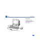
K Service Source Basics Macintosh IIsi
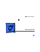
Basics Overview - 1 Overview This manual contains complete repair procedures for the Macintosh IIsi shown at left.
K Service Source Specifications IIsi
Specifications Processor - 1 Processor CPU Coprocessor Motorola 68030 microprocessor 20 MHz 32-bit internal data bus 256-byte instruction and data caches Burst-mode RAM access Built-in memory management unit (MMU) Motorola 68882 floating-point unit (FPU) included on the optional adapter card 20 MHz
Specifications Memory - 2 Memory RAM 2 MB, expandable to 17 MB ROM 512K standard PRAM 256 bytes of parameter memory
Specifications Disk Storage - 3 Disk Storage Floppy Drive Internal 1.
Specifications I/O Interfaces - 4 I/O Interfaces Expansion One slot for either a NuBus or 030 direct slot card Power available (15 W maximum) + 5 V 2.
Specifications I/O Devices - 5 I/O Devices Keyboard Mouse Apple Keyboard, Apple Keyboard II, or Apple Extended Keyboard connected through Apple Desktop Bus (ADB) ports (mini DIN-4) ADB mouse (mini DIN-4)
Specifications Sound and Video - 6 Sound and Video Sound Generator Output impedance of 8–600 ohms Short-circuit protected Disables internal speaker when in use Four-voice, wavetable synthesis and stereo sampling generator
Specifications Electrical - 7 Electrical Line Voltage 100–240 VAC, automatically configured Frequency 50–60 Hz, single phase Maximum Power 100 W (not including monitor)
Specifications Physical - 8 Physical Dimensions Weight Height: 4.0 in. (10 cm) Width: 12.4 in. (31 cm) Depth: 14.9 in. (37.2 cm) 10 lb. (4.5 kg) Configuration of RAM, floppy drives, hard drives, and NuBus expansion cards will vary weight.
K Service Source Troubleshooting IIsi
Troubleshooting General/ - 1 General The Symptom Charts included in this chapter will help you diagnose specific symptoms related to your product. Because cures are listed on the charts in the order of most likely solution, try the first cure first. Verify whether or not the product continues to exhibit the symptom. If the symptom persists, try the next cure. (Note: If you have replaced a module, reinstall the original module before you proceed to the next cure.
Troubleshooting Symptom Charts/Video - 2 Symptom Charts Video Screen is dark, audio and at least one drive operate, fan is running, and LED is lit 1 2 3 4 5 6 7 8 Adjust brightness on monitor. Verify monitor works with different Macintosh. Replace monitor. Refer to appropriate monitor manual to troubleshoot defective monitor. Replace video cable. Replace video card. Replace SIMMs. See Hardware/Memory. Replace logic board. Retain customer’s SIMMs. Replace power supply.
Troubleshooting Symptom Charts/Video (Continued) - 3 Video (Continued) Screen is dark, audio and drive do not operate, but fan is running and LED is lit 1 2 3 Partial or whole screen is bright and audio is present, but no video information is visible 1 2 4 5 6 7 8 3 4 Verify monitor works with different Macintosh. Replace video cable. Replace monitor. Refer to appropriate monitor manual to troubleshoot defective monitor. Remove NuBus cards. Remove peripherals. Replace SIMMs. See Hardware/Memory.
Troubleshooting Symptom Charts/Video (Continued) - 4 Video (Continued) Screen is completely dark, fan is not running, and LED is not lit 1 2 3 4 5 Plug the monitor directly into a wall socket and verify that the monitor has power. Remove NuBus card and switch on power again. (NuBus card draws more than 45 watts.) Remove peripherals. Replace power supply. Replace logic board. Retain customer’s SIMMs.
Troubleshooting Symptom Charts/Floppy Drive - 5 Floppy Drive Audio and video present, but internal floppy drive does not operate 1 2 3 Replace internal floppy drive cable. Replace internal floppy drive. Replace logic board. Retain customer’s SIMMs. Disk ejects; display shows Mac icon with blinking “X” 1 2 3 4 Replace floppy disk. Replace internal floppy drive cable. Replace internal floppy drive. Replace logic board. Retain customer’s SIMMs. Disk will not eject 1 Switch off computer.
Troubleshooting Symptom Charts/Floppy Drive (Continued) - 6 Floppy Drive (Continued) Drive attempts to eject disk but doesn’t 1 2 3 4 Push disk completely in. Remove top cover and attempt to eject the disk. Eject disk manually. Replace floppy drive.
Troubleshooting Symptom Charts/Hard Drive - 7 Hard Drive Internal hard drive runs continuously 1 2 3 Replace hard drive data cable. Replace internal hard drive. Replace logic board. Retain customer’s SIMMs. Internal hard drive will not operate 1 2 3 4 Replace hard drive data cable. Replace hard drive power cable. Replace hard drive. Replace logic board. Retain customer’s SIMMs.
Troubleshooting Symptom Charts/Peripheral - 8 Peripheral Works with internal hard drive or external SCSI device but not with both 1 Cursor does not move 1 2 3 2 3 4 4 5 6 Verify that SCSI select switch on external device shows a different priority from internal hard drive. Replace terminator on the external device. Verify that internal hard drive has a terminator. Replace SCSI select cable. Reboot computer. Verify mouse connection.
Troubleshooting Symptom Charts/Peripheral (Continued) - 9 Peripheral (Continued) Cursor moves, but clicking the mouse button has no effect 1 2 Replace mouse. Replace logic board. Retain customer’s SIMMs. Double-click does not open an application, disk, or server 1 2 Remove duplicate system files. Clear parameter RAM. System 7: Hold down
Troubleshooting Symptom Charts/Peripheral (Continued) - 10 Peripheral (Continued) No response to any key on the keyboard 1 2 3 4 Verify keyboard connection to ADB port. Replace keyboard cable. Replace keyboard. Replace logic board. Retain customer’s SIMMs. Known-good ImageWriter® or ImageWriter II won’t print 1 2 Verify that the System is version 6.0.7 (or later). Verify that the Chooser and Control Panel settings are correct. Check printer DIP switches. Reset PRAM. Replace printer interface cable.
Troubleshooting Symptom Charts/Peripheral (Continued) - 11 Peripheral (Continued) Known-good LaserWriter® won’t print 1 2 3 4 Verify that the System is version 6.0.7 (or later). Verify that the Chooser and Control Panel settings are correct. Reset PRAM. Refer to the Networking and Communications manual.
Troubleshooting Symptom Charts/Miscellaneous - 12 Miscellaneous Clicking, chirping, or thumping 1 2 3 Replace power supply. Disconnect hard drive. If noise disappears, replace drive. Replace logic board. Retain customer’s SIMMs. System shuts down intermittently 1 Check that air vents on the back and top of the case are unobstructed. (Thermal protection circuitry may shut down the system. After 30 to 40 minutes, the system should run.) Replace power cord. Replace power supply. Replace logic board.
Troubleshooting Symptom Charts/Miscellaneous (Continued) - 13 Miscellaneous (Continued) System intermittently crashes or locks up 1 2 3 4 5 6 Verify that the System is version 6.0.7 (or later). Verify that software is known-good. Remove additional RAM and NuBus cards. Replace logic board. Retain customer’s SIMMs. Replace SIMMs. See Hardware/Memory. Replace power supply. No sound from speaker 1 2 3 4 Verify that volume setting in the Control Panel is 1 or above. Reset PRAM. Replace speaker.
Troubleshooting Symptom Charts/Miscellaneous (Continued) - 14 Miscellaneous (Continued) Clock not running 1 2 3 System seems to boot; then message “Finder is old version” appears 1 2 System restarts itself Replace battery. See “Battery Verification” in Additional Procedures. Reset PRAM. Replace logic board. Retain customer’s SIMMs. Clear parameter RAM. System 7: Hold down
Troubleshooting Symptom Charts/Error Chords - 15 Error Chords Error chord sounds during startup sequence 1 2 Perform SIMM verification on customer’s logic board. Replace logic board. Retain customer’s SIMMs.
K Service Source Take Apart IIsi
Take Apart Cover - 1 Cover No preliminary steps are required before you begin this procedure. Push down on the small tabs with your thumbs and at the same time lift up on the large tabs with your forefingers. (The cover may make a loud snap.
Take Apart Fan - 2 Fan Fan Before you begin, remove the following: • Cover • Expansion card Caution: Review the ESD precautions in Bulletins/ Safety.
Take Apart Fan - 3 P lace your thumbs under the fan and using some force pull up until the fan snaps free.
Take Apart Power Supply - 4 Power Supply Power Supply Before you begin, remove the following: • Cover • Expansion card • Fan Caution: Review the ESD precautions in Bulletins/ Safety.
Take Apart Power Supply - 5 1 Metal Tabs 2 Silver-Colored Tab Press the two metal tabs near the rear of the power supply and lift the power supply about 1/2 inch. Pull the silver-colored tab toward the floppy drive and at the same time lift the power supply out of the case.
Take Apart Hard Drive - 6 Hard Drive Before you begin, remove the cover. Caution: Review the ESD precautions in Bulletins/ Safety.
Take Apart Hard Drive - 7 1 Hard Drive Power Cable Hard Drive Data Cable Disconnect the hard drive power cable and hard drive data cable from the logic board.
Take Apart Hard Drive - 8 2 Release the two tabs and lift the drive (along with its carrier) out of the computer. Replacement Note: For information on removing the hard drive from the carrier and returning drives, cables, and carriers to Apple, refer to Additional Procedures in the Hard Drives manual.
Take Apart Floppy Drive - 9 Floppy Drive Before you begin, remove the cover. Floppy Drive Caution: Review the ESD precautions in Bulletins/ Safety.
Take Apart Floppy Drive - 10 1 Floppy Drive Cable 2 Disconnect the floppy drive cable from the logic board. Release the two tabs and lift the floppy drive out of the computer. Replacement Note: Apple recommends using dust shields on 1.4 MB SuperDrives in Macintosh IIsi computers. All 1.4 MB replacement drives ship with the dust shield already installed.
Take Apart Floppy Drive - 11 If you plan to install a dust shield on the current drive, you must first clean the drive.
Take Apart Logic Board - 12 Logic Board Logic Board Before you begin, remove the following: • Cover • Adapter card • Fan • Power supply Caution: Review the ESD precautions in Bulletins/ Safety.
Take Apart Logic Board - 13 1 Hard Drive Power Cable Hard Drive Data Cable Floppy Drive Cable Disconnect these cable connectors from the logic board: • Hard drive power cable • Hard drive data cable • Floppy drive cable
Take Apart Logic Board - 14 2 120-Pin Connector Release Tab Release Tab 3 With the rear of the case facing you, release the two tabs with your forefingers and at the same time push on the 120-pin connector with your right thumb. Slide the logic board toward the front of the case until the board stops.
Take Apart Logic Board - 15 4 J20 Connector (underneath) J19 Connector Caution: Be sure the power on/off button clears the rear panel before you lift the logic board out of the case. While lifting the board, do not touch connector J19 or J20. (The oil from your skin harms the connectors.) Gently lift the board out of the case.
Take Apart Logic Board - 16 Replacement Note: Remove the SIMMs from the defective logic board and install them on the replacement logic board.
Take Apart Speaker - 17 Speaker Before you begin, remove the following: • Cover • Adapter card • Fan • Power supply • Hard drive • Logic board Speaker
Take Apart Speaker - 18 1 2 LED Cables Cable Holders LED LED Holder Push the LED out of the holder. Carefully remove the LED cables from the two cable holders.
Take Apart Speaker - 19 3 Clip Clip Clip Clip Release the four clips and lift the speaker out of the case. Replacement Note: When you replace the speaker and logic board, make sure the metal connector fingers of the speaker contact the metal fingers on the underside of the logic board.
K Service Source Upgrades IIsi
Upgrades 030 Direct Slot Card Adapter/030 Direct Slot Card - 1 Plastic Bracket Adapter/030 Direct Slot Card Before you begin, remove the cover. Caution: Review the ESD precautions in Bulletins/ Safety. 030 Adapter Card Note: The following procedure explains how to remove the 030 adapter card, 030 direct slot card, and plastic bracket.
Upgrades 030 Adapter Card Adapter/030 Direct Slot Card - 2 030 Direct Slot Card 1 Pull straight up on the adapter card and carefully remove it and the direct slot card from the logic board.
Upgrades Adapter/030 Direct Slot Card - 3 2 030 Direct Slot Card Connector 030 Adapter Card If you are replacing the direct slot card, place the adapter card on a flat surface, and carefully pull the direct slot card from the adapter card connector.
Upgrades Adapter/030 Direct Slot Card - 4 3 Latch Plastic Bracket To remove the plastic bracket, press on the latch with a screwdriver and lift the bracket from the power supply. Replacement Note: If you are replacing the direct slot card, retain the plastic bracket and use it with the replacement card.
Upgrades Adapter/NuBus Card - 5 NuBus Card Adapter/NuBus Card Before you begin, remove the cover. Caution: Review the ESD precautions in Bulletins/ Safety.
Upgrades Adapter/NuBus Card - 6 Metal Bracket 1 NuBus Card 2 Access Port NuBus Adapter Card Remove the screws that secure the NuBus adapter card to the access port. Pull straight up on the metal bracket and remove the bracket, NuBus card, and adapter card from the computer.
Upgrades Adapter/NuBus Card - 7 3 NuBus Card Metal Bracket NuBus Adapter Card If you are replacing the NuBus card, place the adapter card on a flat surface, and carefully pull the NuBus card from the adapter card connector.
K Service Source Additional Procedures IIsi
Additional Procedures Battery Verification - 1 Battery Verification Lithium Battery Before you begin, remove the cover. Caution: Review the ESD precautions in Bulletins/ Safety. Warning: If handled or discarded improperly, the lithium battery in the Macintosh IIsi could explode. Review battery-handling and disposal instructions in Bulletins/Safety.
Additional Procedures Battery Verification - 2 1 2 Negative Probe Positive Probe 3 Set the voltmeter to the 10 volts DC scale. Hold the positive probe of the voltmeter to the positive end of the battery and the negative probe to the negative end of the battery. If the battery voltage is below 3.0 volts, replace the battery. Refer to “Battery Replacement” in this chapter.
Additional Procedures Battery Replacement - 3 Battery Replacement Lithium Battery Before you begin, remove the following: • Cover • Expansion cards If handled or discarded improperly, the lithium battery in the Macintosh IIsi could explode. Review battery-handling and disposal instructions in Bulletins/Safety.
Additional Procedures Battery Replacement - 4 1 Using a small flat-blade screwdriver, pry open the latch at the end of the holder and lift off the cover.
Additional Procedures Battery Replacement - 5 2 3 Grasp the battery and remove it from the holder. Return the battery to Apple for proper disposal. For battery packaging and labeling instructions, refer to the safety information in Bulletins/Safety. Replacement Caution: Match the battery end marked “+” to the “+” on the battery holder.
K Service Source Exploded View Macintosh IIsi
Exploded View 1 Exploded View Top Case 630-5804 Fan Assembly 810-6030 Power Supply 661-1616 Adaptor Card and Bracket 815-6246 Logic Board 661-1615 Internal Floppy Drive Cable 591-0025 Floppy Drive Carrier 805-0961 Floppy Drive 661-0474 Hard Drive Data Cable 591-0026 844-0018 Hard Drive Power Cable 591-0027 Bottom Case 810-6032 865-0024 Hard Drive Carrier 805-0980 444-6104 Hard Drive 661-0216 (40 MB) Speaker/ LED Assembly 810-6031