K Service Source Macintosh Plus
K Service Source Basics Macintosh Plus
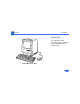
Basics Overview - 1 Overview This manual contains complete repair procedures for the Macintosh Plus, shown at left.
K Service Source Specifications Macintosh Plus
Specifications Introduction - 1 Introduction Specifications information for this product can be found in this chapter and also in the Spec Database, which you can access in one of three ways: — Launch it directly by double-clicking the Apple Spec Database runtime alias at the top level of the Main Service Source CD. — Select "Apple Spec Database" from the Service Source drop-down main menu. — Click the Acrobat toolbar icon for the database, which is near the right end of the toolbar with the letters "SP.
Specifications Processor - 2 Processor CPU Motorola 68000 microprocessor 7.
Specifications Memory - 3 Memory RAM 1 MB, expandable to 4 MB (150 ns or faster SIMMs) ROM 128K PRAM CMOS custom chip with 4.
Specifications Disk Storage - 4 Disk Storage Floppy Drive Internal, double-sided drive: uses 3.5-in.
Specifications I/O Interfaces - 5 I/O Interfaces Floppy Drive External drive port; DB-19 connector SCSI One SCSI parallel port; DB-25 connector Mouse Mouse port; DE-9 connector Keyboard Synchronous serial keyboard bus; RJ-11 connector Serial Two RS-422 serial ports; mini DIN-8 connectors
Specifications I/O Devices - 6 I/O Devices Keyboard 78 keys, including numeric keypad and cursor keys; RJ-11 connector Mouse Mechanical tracking; optical shaft encoding at 3.54 pulses per mm (90 pulses per in.
Specifications Sound and Video - 7 Sound and Video Sound Generator Four-voice sound with 8-bit digital/analog conversion, using 22-kHz sampling rate Video Display 9-in.
Specifications Electrical - 8 Electrical Line Voltage 105–125 VAC Frequency 50–60 Hz Maximum Power 60 W
Specifications Physical - 9 Physical Dimensions Weight Height: 13.6 in. (34.5 cm) Width: 9.6 in. (24.4 cm) Depth: 10.9 in. (27.6 cm) 16 lb. 8 oz. (7.
K Service Source Troubleshooting Macintosh Plus
Troubleshooting General - 1 General The Symptom Charts included in this chapter will help you diagnose specific symptoms related to your product. Because cures are listed on the charts in the order of most likely solution, try the first cure first. Verify whether or not the product continues to exhibit the symptom. If the symptom persists, try the next cure. (Note: If you have replaced a module, reinstall the original module before you proceed to the next cure.
Troubleshooting Symptom Charts/Video - 2 Symptom Charts Video No video, but audio tone is present and drive operates 1 2 3 4 5 Turn contrast control fully clockwise. Check video cable connections. Replace power supply board. Replace neck cable. Replace logic board. Retain customer’s SIMMs. Screen is bright and audio is present, but no video information is present 1 2 Replace power supply board. Replace logic board. Retain customer’s SIMMs.
Troubleshooting Symptom Charts/Drives - 3 Drives Disk ejects; display shows disk icon with blinking “X” 1 2 3 4 Replace Replace Replace Replace Unable to insert disk all the way 1 Insert paper clip into small hole beside drive slot, or switch off system power and hold mouse button down while switching system power back on to complete eject cycle. Then insert disk with metal slot forward and write-protect tab on bottom. Replace floppy drive. 2 bad disk. floppy drive cable. floppy drive. logic board.
Troubleshooting Symptom Charts/Drives (Continued) - 4 Drives (Continued) Does not read disks on internal drive 1 2 3 4 5 6 Replace bad disk. Replace floppy drive cable. Replace Mylar RFI shield. Replace floppy drive. Verify ROMs on the logic board. Replace logic board. Retain customer’s SIMMs. Does not read disks on external drive 1 2 3 4 5 6 Replace bad disk. Replace floppy drive cable. Replace Mylar RFI shield. Replace external drive. Verify ROMs on the logic board. Replace logic board.
Troubleshooting Symptom Charts/Drives (Continued) - 5 Drives (Continued) Audio tone sounds at power on, video is present, but drive does not operate 1 2 3 Replace floppy drive cable. Replace floppy drive. Replace logic board. Retain customer’s SIMMs. Drive runs continuously 1 2 3 4 Replace Replace Replace Replace 400K drive does not boot 1 If logic board has Rev. A ROMs and drive stepper motor is serial number F518 or higher, upgrade to Rev. B ROMs. Replace floppy drive. 2 bad disk.
Troubleshooting Symptom Charts/Peripherals - 6 Peripherals Cursor does not move 1 2 3 4 Connect mouse. Clean mouse. Replace mouse. Replace logic board. Retain customer’s SIMMs. Cursor moves but clicking mouse produces no response 1 2 Replace mouse. Replace logic board. Retain customer’s SIMMs. No response to any key on keyboard 1 2 3 Replace keyboard cable. Replace keyboard. Replace logic board. Retain customer’s SIMMs. No response from a particular key 1 2 3 Replace keyswitch.
Troubleshooting Symptom Charts/Peripherals (Continued) - 7 Peripherals (Continued) Known-good ImageWriter or ImageWriter II does not print 1 2 Known-good LaserWriter does not print 1 2 3 4 5 3 Make sure that Chooser and Control Panel are set correctly. Check that system software version is compatible. Replace software with known-good. Reset PRAM. Replace interface cable. Replace logic board. Retain customer’s SIMMs. Make sure that Chooser and Control Panel are set correctly.
Troubleshooting Symptom Charts/Miscellaneous - 8 Miscellaneous When turned on, the Macintosh Plus continuously beeps and tries to power up Clicking or chirping sound 1 2 3 4 1 2 3 4 Perform voltage adjustment. Refer to Adjustments. Disconnect internal disk drive. If this eliminates problem, replace drive. Replace logic board. Retain customer’s SIMMs. Replace power supply board, logic board, and internal drive; then turn on Macintosh.
Troubleshooting Symptom Charts/Miscellaneous (Continued) - 9 Miscellaneous (Continued) Smoke/odor issues from the Macintosh Plus Replace power supply board. No video, no audio tone, and no drive operation 1 2 3 4 5 6 Connect power cord. Turn power on. Replace power cord. Check fuse. Replace power supply board. Replace logic board. Retain customer’s SIMMs.
Troubleshooting Symptom Charts/Miscellaneous (Continued) - 10 Miscellaneous (Continued) MacTest displays 128K/512K when 1 MB Macintosh Plus is tested Replace Macintosh Plus logic board. Retain customer’s SIMMs. When developer’s switch is installed, Macintosh Plus sometimes resets intermittently Remove switch and file it down about 1/16 inch.
Troubleshooting Symptom Charts/Miscellaneous (Continued) - 11 Miscellaneous (Continued) Macintosh Plus hangs on startup 1 If logic board has ROMs 342-0341-A or B (ROM HI) and 3420342-A (ROM LO) and a peripheral device is connected to SCSI port, peripheral device must be turned on before powering on Macintosh Plus. Macintosh Plus boots but keyboard behaves erratically 1 2 Replace keyboard. Check that logic board grounding clip is not touching solder points beneath logic board. Replace logic board.
K Service Source Take Apart Macintosh Plus
Take Apart Cover - 1 Cover Cover No preliminary steps are required before you begin this procedure. Warning: This product contains high voltage and a high-vacuum picture tube. To prevent serious injury, review CRT Safety in Bulletins/Safety. ± Battery Compartment Cover Reset/Interrupt Switch 1 2 Remove the battery compartment cover. Remove the reset/ interrupt switch, if present.
Take Apart Cover - 2 3 Using a Torx screwdriver, remove the case screws, including the one in the battery compartment. Using the pull-apart tool, gently pry off the cover. ±Warning: The edges of the metal chassis may be sharp. When moving the computer with the cover off, be sure to handle the chassis carefully.
Take Apart Power/Sweep Board - 3 Power/Sweep Board Ground Lug Anode Cap Power/Sweep Board Before you begin, • Remove the cover • Discharge the CRT • Remove the anode cap This product contains high voltage and a high-vacuum picture tube. To prevent serious injury, review CRT Safety in Bulletins/Safety. ±Warning: Discharge Tool Warning: Never use a grounding wriststrap until after discharging the CRT.
Take Apart Power/Sweep Board - 4 1 Yoke Cable Logic Board Cable Neck Cable 2 Screw & Lockwasher Disconnect the following cable connectors from the power/sweep board: • Yoke cable • Logic board cable • Neck cable Remove the screw and lockwasher that hold the ground wire to the chassis.
Take Apart Power/Sweep Board - 5 3 Note: You may need to remove the insulating paper from the power/ sweep board to access the mounting screws. Remove the three mounting screws and washers, and lift the power/sweep board from the chassis. Replacement Note: After replacing all parts except the cover, perform the voltage and video adjustment procedures. See “Voltage” and “Video” in Adjustments.
Take Apart Power/Sweep Board - 6 Replacement Note: When sending Apple a defective power/sweep board, be sure to include the cable that connects to the logic board. Make sure the contrast control knob and battery have been removed from the defective board and reinstalled onto the exchange board.
Take Apart Logic Board - 7 Logic Board Before you begin, • Remove the cover • Discharge the CRT Warning: This product contains high voltage and a high-vacuum picture tube. To prevent serious injury, review CRT Safety in Bulletins/Safety. ± Never use a grounding wriststrap until after discharging the CRT.
Take Apart Logic Board - 8 1 Logic Board Cable Floppy Drive Cable Disconnect the following cable connectors from the logic board: • Floppy drive cable • Logic board cable
Take Apart Logic Board - 9 2 Caution: When removing the logic board, be careful not to damage the SIMMs — especially the larger DIP SIMMs that may be installed on the board. Pull back on the top of the logic board, and carefully slide out the logic board.
Take Apart Logic Board - 10 3 Note: If your replacement board is Rev. D (part number 820XXXX-D) or higher, you should install a ground clip. Do not use the ground clip with any logic board lower than Rev. D. Caution: Contact between the ground clip and pins or solder points on the underside of the logic board could cause a short, resulting in erratic keyboard behavior.
Take Apart Logic Board - 11 clip does not touch any solder points. Install the ground clip to the inner plastic lip on the bottom front bezel. Replacement Note: Remove the SIMMs from the defective logic board and install them on the replacement logic board. Replacement Note: When exchanging the 512K logic board, you must swap ROMs to the new logic board.
Take Apart Logic Board - 12 Replacement Note: After replacing all parts except the cover, perform the voltage adjustment procedures. See “Voltage” in Adjustments.
Take Apart CRT - 13 CRT CRT Before you begin, • Remove the cover • Discharge the CRT • Remove the power/sweep board This product contains high voltage and a high-vacuum picture tube. To prevent serious injury, review CRT Safety in Bulletins/Safety. ±Warning: Never use a grounding wriststrap until after discharging the CRT.
Take Apart CRT - 14 Handle the CRT by its sides only. Do not grasp the neck on the CRT or touch the anode. ±Warning: 1 2 Slide the CRT socket cable straight off the neck of the CRT. Remove the four mounting screws and the ground wire, and lift the CRT off the bezel. If you need to dispose of the CRT, refer to the CRT disposal instructions in Bulletins/Safety.
Take Apart CRT - 15 Replacement Note: If you replace the CRT, perform the voltage, video, and yoke adjustment procedures. See “Voltage,” “Video,” and “Yoke” in Adjustments.
Take Apart Floppy Drive - 16 Floppy Drive Before you begin, • Remove the cover • Discharge the CRT • Remove the logic board This product contains high voltage and a high-vacuum picture tube. To prevent serious injury, review CRT Safety in Bulletins/Safety. ±Warning: Floppy Drive Never use a grounding wriststrap until after discharging the CRT.
Take Apart Floppy Drive - 17 Remove the four mounting screws, and slide the floppy drive out of the chassis. Replacement Note: Before you install a replacement drive, remove the dust shield, if there is one.
Take Apart Chassis - 18 Chassis Before you begin, • Remove the cover • Discharge the CRT • Remove the logic board • Remove the power/sweep board • Remove the floppy drive Warning: This product contains high voltage and a high-vacuum picture tube. To prevent serious injury, review CRT Safety in Bulletins/Safety.
Take Apart Chassis - 19 Never use a grounding wriststrap until after discharging the CRT. ±Warning: Remove the five mounting screws and lift the chassis off the bezel.
K Service Source Upgrades Macintosh Plus
Upgrades Memory Upgrade - 1 Memory Upgrade Before you begin, • Remove the cover • Discharge the CRT • Remove the logic board This product contains high voltage and a high-vacuum picture tube. To prevent serious injury, review CRT Safety in Bulletins/Safety. ±Warning: Logic Board Warning: Never use a grounding wriststrap until after discharging the CRT.
Upgrades Memory Upgrade - 2 Logic Board R8 Bank A Bank B Note: You can configure the Macintosh Plus with 1 MB, 2.5 MB, or 4 MB of RAM. The standard 1 MB configuration has a SIMMs resistor installed in R8 and four 256K SIMMs in both banks. To add memory, you must install SIMMs and remove the SIMMs resistor. Note: The Macintosh Plus requires 150-ns or faster SIMMs. RAM speed is indicated by the -xx number after the manufacturer’s part number (-15 indicates a 150-ns SIMM).
Upgrades Memory Upgrade - 3 Clip one end of resistor R8 and move the resistor away from the clipped lead. Replacement Note: You can retack the resistor later, if necessary. R8 2.5 MB RAM Upgrade Install two 1 MB SIMMs in Bank A and two 256K SIMMs in Bank B. Bank A Bank B 4 MB RAM Upgrade Install two 1 MB SIMMs in Bank A and two 1 MB SIMMs in Bank B.
K Service Source Adjustments Macintosh Plus
Adjustments Voltage - 1 Power/Sweep Board Voltage You must verify voltages after you replace the logic board or the power/sweep board. Before you begin, remove the cover. Warning: This product contains high voltage and a high-vacuum picture tube. To prevent serious injury, review CRT Safety in Bulletins/Safety.
Adjustments Voltage - 2 Because you must make voltage adjustments from the rear of the compu-ter, use a mirror to view the computer screen. Do not reach around the computer to adjust the controls.
Adjustments Voltage - 3 1 2 3 External Drive Port Set the voltmeter to 20 volts. Connect the Macintosh voltage test cable (Apple part number 0770135) to the external drive port. Caution: Shorting the test cable plugs to each other can damage the computer. Pull the hoods over the plugs. Connect the black voltmeter test lead between the voltmeter ground terminal and the computer chassis.
Adjustments Voltage - 4 4 Connect the orange test cable lead to the voltage input terminal on the voltmeter.
Adjustments Voltage - 5 5 Switch on the computer. 7 Switch off power. 6 Voltage Regulator 8 Adjust the voltage regulator on the power/ sweep board to between 11.90 and 12.75 volts. Disconnect the orange test lead and pull the insulated hood over the plug.
Adjustments Voltage - 6 9 Connect the red test cable lead to the voltage input terminal on the voltmeter. 10 Switch on the computer. Voltage Regulator 11 Adjust the voltage regulator on the power/ sweep board to between 4.85 and 5.15 volts.
Adjustments Voltage - 7 12 Switch off power. 13 Disconnect the red test lead and pull the insulated hood over the plug. Voltage Regulator 14 Repeat the tests to verify that both voltages are within the specified tolerances. Note: If the power/sweep board will not adjust so that both voltages fall within tolerance, replace the board.
Adjustments Yoke - 8 Yoke If you replace the CRT, you may need to adjust the yoke. Yoke Before you begin: • Remove the cover • Discharge the CRT This product contains high voltage and a high-vacuum picture tube. To prevent serious injury, review CRT Safety in Bulletins/Safety.
Adjustments Yoke - 9 Because you must make yoke adjustments from the rear of the computer, use a mirror to view the computer screen. Do not reach around the computer to adjust the controls.
Adjustments Yoke - 10 Tilt Adjustment Note: If glue holds the yoke collar in place, use an art knife to cut through the glue. 1 Yoke Collar Yoke Clamp Screw 2 3 Loosen the yoke clamp screw two or three turns. Switch on the computer. With one hand, grasp the plastic spokes of the yoke collar and rotate the yoke collar until the top and bottom edges of the picture are parallel with the top and bottom of the bezel.
Adjustments Yoke - 11 4 5 6 Yoke Collar Yoke Clamp Screw 7 Switch off and unplug the computer. Discharge the CRT. Hold the plastic collar in position and slowly tighten the yoke clamp screw so that the collar cannot slip. Do not overtighten the screw. Replace the cover and switch on the computer. Make sure the top and bottom edges of the picture are parallel with the top and bottom of the bezel.
Adjustments Yoke - 12 Centering Ring Adjustment Note: If glue holds the yoke collar in place, use an art knife to cut through the glue. To center the picture, hold the front centering ring steady and move the rear ring. Then hold the rear centering ring steady and move the front ring.
Adjustments Video - 13 Video Power/Sweep Board You must perform the video adjustments whenever the CRT or the power/sweep board is replaced. Before you begin, remove the cover. Warning: This product contains high voltage and a high-vacuum picture tube. To prevent serious injury, review CRT Safety in Bulletins/Safety.
Adjustments Video - 14 Because you must make video adjustments from the rear of the compu-ter, use a mirror to view the computer screen. Do not reach around the computer to adjust the controls. ±Warning: Switch on the computer.
Adjustments Video - 15 Brightness and Contrast 1 Brightness Control External Contrast Control 2 3 Turn the external contrast control fully clockwise. Turn the brightness control fully counterclockwise so that white lines are visible. Turn the brightness control clockwise until the white lines just disappear. Turn the external contrast control 1/8 of a turn counterclockwise.
Adjustments Video - 16 Size Adjustment Width Control Height Control Using the alignment tool, adjust the width control until the raster is 7 inches (177.8 mm) wide. Using the alignment tool, adjust the height control until the raster is 4.7 inches (119.4 mm) high.
Adjustments Video - 17 Focus Adjustment 1 2 Focus Control Turn the focus control clockwise to its limit. Turn the focus control counterclockwise 1/8 of a turn.
K Service Source Exploded View Macintosh Plus
Exploded View 1 Exploded View CRT and Yoke Assembly 076-0103 Front Bezel 810-0379 810-0385 (Platinum) Internal Drive Shield 805-0217 (800K) CRT Socket Cable 590-0160 800K Floppy Drive 661-0345 Internal Drive Cable 590-0437 Insulator Shield 725-0011 Power/ Sweep Board 661-0462 110V 661-76214 220V Chassis 805-0766 462-3100 426-1001 Logic Board 661-0525 Rear Housing 630-5211 630-5235 (Platinum) 426-1007 435-5002 RFI Shroud 805-5047