K Service Source Macintosh Portable
K Service Source Basics Macintosh Portable
Basics Overview - 1 Overview This manual contains complete repair procedures for the Macintosh Portable shown at left.
K Service Source Specifications Macintosh Portable
Specifications Processor - 1 Processor CPU Addressing Wait States Motorola 68HC000, 16-bit CMOS microprocessor 15.
Specifications Memory - 2 Memory RAM 1 MB using thirty-two 32K by 8-bit static RAM chips; 100 ns access time; addressing supports up to 9 MB Expandable to 2 MB with optional 1 MB RAM expansion card Expandable to 4 MB with optional 3 MB RAM expansion card (backlit model) ROM 256K using two 128K by 8-bit devices; 150 ns access time; addressing supports up to 4 MB PRAM 128 bytes of system parameter memory VRAM 32K of static video display memory
Specifications Disk Storage - 3 Disk Storage Floppy Drive Internal 1.
Specifications I/O Interfaces - 4 I/O Interfaces Floppy Drive DB-19 connector Supports Macintosh 800K Disk Drive, Apple 3.5 Drive, Apple SuperDrive, and Apple Hard Disk 20 SCSI 1.
Specifications I/O Interfaces - 5 Power Adapter Power adapter port Sound Stereo sound-in port Video DA-15 connector Supports the connection of external video devices
Specifications I/O Devices - 6 I/O Devices Keyboard 63 keys N-key rollover Apple Desktop Bus (ADB) interface US, British, French Canadian, Japanese, German, Spanish, French, Swedish, and Italian versions available Low-Power ADB Mouse Low-power version of the ADB mouse Opto-mechanical type ADB interface Trackball ADB interface
Specifications Numeric Keypad (Optional) I/O Devices - 7 18 keys ADB interface US, Pacific, and European versions available
Specifications Sound and Video - 8 Sound and Video Sound Generator Video Display Apple Sound Chip One-or four-voice mono (one or two voices in stereo) with 4-bit digital-to-analog conversion using a 22-kHz sampling rate Filtered by two Sony sound chips 10-in. (diagonal) screen Reflective, active-matrix, liquid crystal, flat-panel display 640 by 400 pixels, 75 dpi .28 mm dot size; .
Specifications Electrical - 9 Electrical Main Battery Backup Battery Sealed lead-acid 6.5 V Up to 10 hours (fully charged battery); time depends on system configuration and power management settings 9 V transistor Power Adapter Input voltage: Output voltage: 85–270 VAC (100/240 nominal), 48–62 Hz (50/60 nominal) 7.0–7.6 V (7.5 nominal), 5 mA–2.0 A (1.
Specifications Battery Recharger (Optional) Electrical - 10 Input voltage: 7.5 VAC Battery recharger output voltage: 6.
Specifications Physical - 11 Physical Dimensions (Display Open) Weight (With Battery) Width: 15.25 in. (387.35 mm) Height: 11.0 in. (279.4 mm) Depth: 14.83 in. (365.25 mm) Height at rear panel: 4.05 in. (102.87 mm) Height at front panel: 2.10 in. (53.34 mm) 13.75 lb. (6.25 kg) without hard drive 15.75 lb. (7.
K Service Source Troubleshooting Macintosh Portable
Troubleshooting General - 1 General The Symptom Charts included in this chapter will help you diagnose specific symptoms related to your product. Because cures are listed on the charts in the order of most likely solution, try the first cure first. Verify whether or not the product continues to exhibit the symptom. If the symptom persists, try the next cure. (Note: If you have replaced a module, reinstall the original module before you proceed to the next cure.
Troubleshooting Symptom Charts/Power - 2 Symptom Charts Power Screen is blank; computer is not responding 1 2 3 4 5 6 7 8 If computer is new, remove plastic sheet from between battery and contacts. Reset power manager. Connect power adapter and restart computer in three or four minutes. Replace main battery. Check keyboard cable connections. Replace keyboard. Replace keyboard cable. Replace logic board. Retain customerÕs SIMMs.
Troubleshooting Symptom Charts/Power (Continued) - 3 Power (Continued) After main battery is removed, some Control Panel settings are different 1 2 Did you replace battery cover after removing main battery? If so, power interruption destroyed settings. Restore contents of Control Panel. Replace backup battery. Power adapter is plugged in and connected; battery DA does not indicate charger is connected 1 2 3 4 Verify that charger is connected properly. Replace main battery. Replace power adapter.
Troubleshooting Symptom Charts/Power (Continued) - 4 Power (Continued) Low-power warning appears soon after you start to use computer 1 2 3 Attach power adapter. Make sure peripherals display low-power icon. Reduce use of power-consuming devicesÑfor example, floppy drive, hard drive, modem, and speakerÑor connect power adapter. Battery does not retain charge, even when computer is not in use 1 2 3 4 5 Upgrade to system software 6.0.5 or later. Replace battery. Replace keyboard.
Troubleshooting Symptom Charts/Video - 5 Video Some pixels never come on; no pattern If display contains six or more voids, replace LCD display. Maximum of five permanently OFF pixels (voids) is acceptable. Some pixels are always black; no pattern If any pixel is on constantly, replace LCD display. Row of pixels is always black 1 2 3 Replace LCD display. Replace display cable. Replace logic board. Retain customerÕs SIMMs. Row of pixels never blackens 1 2 3 Replace LCD display.
Troubleshooting Symptom Charts/Video (Continued) - 6 Video (Continued) Display is blurred 1 2 Adjust angle of display. Use Control Panel to adjust screen contrast. Display is too dark 1 2 3 4 Move computer closer to direct light or move light source closer to computer. Use Control Panel to adjust screen contrast. Replace LCD display. Replace logic board. Retain customerÕs SIMMs. 1 2 3 Adjust angle of display. Use Control Panel to adjust screen contrast. Replace LCD display.
Troubleshooting Symptom Charts/Video (Continued) - 7 Video (Continued) Backlight level cannot be changed Use version 1.3 of Portable CDEV. Backlight does not operate 1 2 3 Display is blank, though computer appears to operate correctly 4 5 Use version 1.3 of Portable CDEV. Check inverter PCA connections. Replace inverter PCA. Refer to ÒLCD Display (Backlit)Ó in Take Apart. Replace LCD Display. Replace logic board. Retain customerÕs SIMMs. 1 2 3 4 Check display cable connection. Replace LCD display.
Troubleshooting Symptom Charts/Floppy Drive - 8 Floppy Drive Audio and video are present, but internal drive does not operate 1 2 3 4 Replace floppy disk. Replace floppy drive. Replace floppy drive cable. Replace logic board. Retain customerÕs SIMMs. Disk ejects while booting; display shows Mac icon with blinking ÒXÓ 1 2 3 4 Replace bad system disk with known good. Replace floppy drive. Replace floppy drive cable. Replace logic board. Retain customerÕs SIMMs.
Troubleshooting Symptom Charts/Floppy Drive (Continued) - 9 Floppy Drive (Continued) Disk does not eject 1 3 4 5 Shut down computer, press and hold trackball or mouse button, and switch on computer. Eject disk manually by pushing opened paper clip into hole near drive. Replace floppy drive. Replace floppy drive cable. Replace logic board. Retain customerÕs SIMMs. 1 2 3 4 Verify that disk is Apple-certified. Replace floppy disk. Replace floppy drive. Replace logic board. Retain customerÕs SIMMs.
Troubleshooting Symptom Charts/Hard Drive - 10 Hard Drive Internal hard drive does not operate 1 2 3 4 5 Switch on external SCSI devices connected to Portable. Check hard drive cable connection. Use HD SC Setup to see whether drive is visible. If it is, reinitialize drive. Replace hard drive. Replace logic board. Retain customerÕs SIMMs.
Troubleshooting Symptom Charts/Peripherals - 11 Peripherals After external SCSI device is connected, computer no longer boots 1 2 3 4 Switch on external SCSI device before starting computer. Verify that cable termination is correct. Verify that no two SCSI devices have same device address. Replace logic board. Retain customerÕs SIMMs. Cursor does not move when you use trackball 1 2 3 4 5 Reset power manager. Check cable connections between trackball and logic board. Replace trackball cable.
Troubleshooting Symptom Charts/Peripherals (Continued) - 12 Peripherals (Continued) Cursor intermittently does not move or moves erratically 1 2 Clean trackball ball and internal rollers. Replace trackball. Cursor does not move when you use mouse. 1 2 3 4 5 Check mouse connection to ADB port. Reset power manager. Clean mouse ball and inside mouse. Replace mouse. Replace logic board. Retain customerÕs SIMMs.
Troubleshooting Symptom Charts/Peripherals (Continued) - 13 Peripherals (Continued) No response to any key on keyboard 1 2 3 4 Reset power manager by pressing reset and interrupt switches simultaneously. Check keyboard connection to logic board. Replace keyboard. Replace logic board. Retain customerÕs SIMMs. Known-good ImageWriter, ImageWriter II, or LQ doesnÕt print 1 2 3 4 Verify that System is 6.0.5 or later. Verify Chooser settings. Replace printer cable. Replace logic board.
Troubleshooting Symptom Charts/Peripherals (Continued) - 14 Peripherals (Continued) Device connected to modem port doesnÕt work 1 2 3 Verify that External Modem is selected in the Portable CDEV. Verify that System is 6.0.5 or later. Replace logic board. Retain customerÕs SIMMs. Serial devices are unrecognized or garbage is transmitted and/or received 1 2 Use version 1.0 of Portable INIT. Upgrade to system software 6.0.5 or later.
Troubleshooting Symptom Charts/Peripherals (Continued) - 15 Peripherals (Continued) When using an external modem: after exiting a communication application and putting the computer to sleep three or four times, the computer freezes when it comes out of system sleep Upgrade to system software 6.0.5 or later.
Troubleshooting Symptom Charts/Internal Modem - 16 Internal Modem Internal modem options do not appear in Portable CDEV when modem is installed 1 2 3 Reseat modem card. Replace modem card. Replace logic board. Retain customerÕs SIMMs. Modem does not respond properly to AT instructions 1 2 Verify that baud rate and data format settings of communications application are compatible with Portable Data Modem 2400 and remote modem. Replace modem card. 1 2 Replace modem card. Replace logic board.
Troubleshooting Symptom Charts/Internal Modem (Continued) - 17 Internal Modem (Continued) Modem does not respond to incoming call 1 2 3 Modem has no sound output If system doesnÕt respond to incoming call during sleep mode, select When Phone Rings option in Automatic Wake-up section of Portable CDEV . Replace modem card. Replace logic board. Retain customerÕs SIMMs. Replace modem card.
Troubleshooting Symptom Charts/Miscellaneous - 18 Miscellaneous Screen goes blank and computer shuts down every few minutes Adjust sleep delay in Control Panel or connect power adapter. Some applications seem to run slower after few seconds Disable system rest. Hard disk is slow to respond, or screen goes blank too often Adjust sleep delay in Control Panel or connect power adapter.
Troubleshooting Symptom Charts/Miscellaneous (Continued) - 19 Miscellaneous (Continued) Speaker doesnÕt work 1 2 3 4 Verify that volume setting in Control Panel is 1 or above. Check speaker connection to logic board. Replace speaker. Replace logic board. Retain customerÕs SIMMs. Screen suddenly goes blank Press any key except Caps Lock. Error chords sound during startup Replace logic board. Retain customerÕs SIMMs.
Troubleshooting Symptom Charts/Macintosh Portable Startup Problems Macintosh Portable Startup Problems Flowchart 1 START Reset power manager. Turn on system without startup disk (press any key except ). Do startup tones sound? No Is any video displayed? No Yes Yes 1. Replace speaker. 2. Replace logic board. Is startup tone normal? No Replace logic board. Yes Is gray pattern displayed? Yes 1 1. Replace keyboard. 2. Replace keyboard cable. 3. Replace logic board. No 1.
Troubleshooting Symptom Charts/Macintosh Portable Startup Problems Macintosh Portable Startup Problems Flowchart 2 1 Is disk icon with question mark displayed? No Replace logic board. Go to Start Yes Insert System Tools in floppy drive. Does desktop appear? Do you hear sounds from disk drive? No Yes Yes END 1. Replace keyboard. 2. Replace keyboard cable. 3. Replace logic board. Yes 1. 2. 3. 4. Do trackball and button function correctly? No No Use known-good startup disk.
K Service Source Take Apart Macintosh Portable
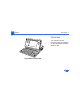
Take Apart Rear Cover - 1 Rear Cover No preliminary steps are required before you begin this procedure. Rear Cover Review the ESD precautions in Bulletins/Safety.
Take Apart Rear Cover - 2 Press the two plastic cover latches, pivot the rear of the cover up, and lift off the rear cover.
Take Apart Keyboard Cover - 3 Keyboard Cover Keyboard Cover No preliminary steps are required before you begin this procedure. Review the ESD precautions in Bulletins/Safety. 1 Push the carrying handle toward the computer and open the display.
Take Apart Keyboard Cover - 4 2 3 Foot Position the computer upright on the rear panel. Insert the tip of a screwdriver under the center of each foot; gently lift the foot away from the case and remove it.
Take Apart Keyboard Cover - 5 4 5 Insert a jeweler’s screwdriver into the center hole at the topright corner of the bottom case. Push in the screwdriver and unsnap the corner of the keyboard cover. Repeat this step to unsnap the left corner of the keyboard cover.
Take Apart Keyboard Cover - 6 6 7 Place the computer flat on the grounded surface. Starting at the edges and working toward the center, slide your index fingers between the bottom case and the keyboard cover until the cover releases. Note: Two latches attach the center of the cover to the bottom case, so you’ll feel some resistance as you lift the center cover.
Take Apart Main Battery - 7 Main Battery Before you begin, remove the rear cover. Review the ESD precautions in Bulletins/Safety. Main Battery Caution: The main battery is a sealed, lead-acid battery that contains toxic materials. Review battery handling and disposal instructions in Bulletins/ Safety.
Take Apart Main Battery - 8 1 2 Main Battery Battery Cover Press the two plastic tabs at the front of the battery cover and slide the battery cover toward the rear of the computer. Lift out the main battery. Caution: You must reinstall the battery cover if you are doing anything other than replacing the main battery. Failure to reinstall the cover leaves power connected to the logic board and could damage new and old modules.
Take Apart Backup Battery - 9 Backup Battery Before you begin, remove the following: • Rear cover • Main battery cover Caution: Review the ESD precautions in Bulletins/ Safety.
Take Apart Backup Battery - 10 Note: Removing the backup battery erases the contents of parameter RAM. Before removing the backup battery, be sure to note all the Control Panel settings so you can restore them after completing your repairs.
Take Apart Backup Battery - 11 1 2 Backup Battery Component Using the tip of a jeweler’s screwdriver, lift the edge of the backup battery far enough to grab the battery with your fingers. Remove the battery from its compartment. Disconnect the battery cable from the battery.
Take Apart Hard Drive - 12 Hard Drive Before you begin, remove the following: • Rear cover • Main battery • Keyboard cover • All option cards Caution: Review the ESD precautions in Bulletins/ Safety.
Take Apart Hard Drive - 13 Caution: Remember to replace the battery cover after removing the main battery. Failure to put the cover on leaves power connected to the logic board. Removing and replacing modules with power available could damage any module.
Take Apart Hard Drive - 14 1 Hard Drive Disconnect the following cable connectors from the logic board: • Display cable from J19 • Hard drive cable from J18
Take Apart Hard Drive - 15 2 3 Plastic Latch Hard Drive Cable Hard Drive Plastic Latch Close the display and move the hard drive cable toward the rear of the computer. Caution: Do not loosen or remove the Torx screws that attach the hard drive to the drive shield. Doing so could irreparably damage the hard drive. Unsnap the two plastic latches and remove the hard drive (with shield) from the subframe.
Take Apart Hard Drive - 16 Replacement Note: For information on removing the hard drive form the carrier and returning drives, cables, and carriers to Apple, refer to Additional Procedures in the Hard Drives Manual.
Take Apart Upper Floppy Drive - 17 Upper Floppy Drive Before you begin, remove the following: • Rear cover • Main battery • All option cards Caution: Review the ESD precautions in Bulletins/ Safety.
Take Apart Upper Floppy Drive - 18 Caution: Remember to replace the battery cover after removing the main battery. Failure to reinstall the cover leaves power connected to the logic board. Removing and replacing modules with power available could damage any modules.
Take Apart Upper Floppy Drive - 19 1 2 3 Plastic Latch Upper Floppy Drive Floppy Drive Cable Plastic Latch Disconnect the floppy drive cable from the floppy drive. Unsnap the two plastic latches and remove the floppy drive (with retainer) from the subframe. Depress the two metal tabs and remove the floppy drive mechanism from the retainer.
Take Apart Upper Floppy Drive - 20 Replacement Note: Before you install a replacement 1.4 MB SuperDrive, you must remove the dust shield.
Take Apart Lower Floppy Drive - 21 Lower Floppy Drive Before you begin, remove the following: • Rear cover • Main battery • All option cards • Upper floppy drive (if installed) • Hard drive (if installed) Lower Floppy Drive Caution: Review the ESD precautions in Bulletins/ Safety.
Take Apart Lower Floppy Drive - 22 Caution: Remember to replace the battery cover after removing the main battery. Failure to reinstall the cover leaves power connected to the logic board. Removing and replacing modules with power available could damage any modules.
Take Apart Lower Floppy Drive - 23 1 2 Disconnect the floppy drive cable from the floppy drive. Remove the floppy drive from the subframe. Replacement Note: Before you install a replacement 1.4 MB SuperDrive, you must remove the dust shield.
Take Apart Keyboard Components - 24 Keyboard Components Trackball/Keypad Keyboard Before you begin, remove the following: • Rear cover • Main battery • Keyboard cover Caution: Review the ESD precautions in Bulletins/ Safety.
Take Apart Keyboard Components - 25 Caution: Remember to replace the battery cover after removing the main battery. Failure to reinstall the cover leaves power connected to the logic board. Removing and replacing modules with power available could damage any modules.
Take Apart Input Device Cable Keyboard Components - 26 Note: The take apart procedure is the same for the keyboard, trackball, and numeric keypad. 1 Disconnect the flat cable from the device you want to remove.
Take Apart Keyboard Components - 27 2 3 Starting at one side of the device, pull or pry up the frame of the device while releasing each plastic retainer clip. After you release all the clips, lift the back end of the device up and out of the computer.
Take Apart Speaker - 28 Speaker Before you begin, remove the following: • Rear cover • Main battery • Keyboard cover Speaker Caution: Review the ESD precautions in Bulletins/ Safety.
Take Apart Speaker - 29 Caution: Remember to replace the battery cover after removing the main battery. Failure to reinstall the cover leaves power connected to the logic board. Removing and replacing modules with power available could damage any modules.
Take Apart Speaker - 30 1 Speaker 2 Disconnect the speaker cable from connector J16 on the logic board. Push out the two latches and remove the speaker from the subframe.
Take Apart Display Assembly - 31 Display Assembly Display Assembly Before you begin, remove the following: • Rear cover • Main battery • Keyboard cover Caution: Review the ESD precautions in Bulletins/ Safety.
Take Apart Display Assembly - 32 Caution: Remember to replace the battery cover after removing the main battery. Failure to reinstall the cover leaves power connected to the logic board. Removing and replacing modules with power available could damage any modules.
Take Apart Display Assembly - 33 1 Display Cable Disconnect the display cable from connector J19 on the logic board.
Take Apart Display Assembly - 34 2 Left Clutch Retainer 3 Left Clutch Cover Twist the left clutch cover back and forth and pull it away from the display. Lift and remove the left clutch retainer.
Take Apart Display Assembly - 35 4 Left Clutch Mechanism 5 Pull the display with your right hand while maintaining slight outward pressure on the computer with your left hand. This movement pulls off the left clutch mechanism (1). Disengage and remove the display assembly from the right clutch mechanism (2).
Take Apart LCD Display (Nonbacklit) - 36 LCD Display (Nonbacklit) LCD Display (nonbacklit) Before you begin, remove the following: • Rear cover • Main battery • Keyboard cover • Display assembly
Take Apart LCD Display (Nonbacklit) - 37 Caution: The LCD display is extremely susceptible to ESD damage. Review the ESD precautions in Bulletins/ Safety. Handle the display by the edges and do not touch the component side or remove the tape.
Take Apart LCD Display (Nonbacklit) - 38 Caution: Remember to replace the battery cover after removing the main battery. Failure to reinstall the cover leaves power connected to the logic board. Removing and replacing modules with power available could damage any modules.
Take Apart LCD Display (Nonbacklit) - 39 Carrying Handle Mounting Screw Mounting Screw 1 Note: Later model Portables and replacement displays have two Phillips screws securing the bezel to the housing. 2 Display Bezel Center Pivot Cover Slide the carrying handle from the display to its fully extended position. Remove the two bezel mounting screws, if present.
Take Apart LCD Display (Nonbacklit) - 40 3 Center Pivot Cover Turn the opening of the center pivot cover toward the display. Pull the cover from the display housing.
Take Apart LCD Display (Nonbacklit) - 41 4 5 Display Latch Opening 6 Insert a jeweler’s screwdriver into the display latch opening on the right side of the display housing. Push the screwdriver into the opening until you hear a click. Pull the display bezel toward you with your fingers while you push the display housing with your thumb. The two parts separate about 1/8 inch. Repeat for the left side.
Take Apart LCD Display (Nonbacklit) - 42 7 Display Bezel Carrying Handle Lift the display bezel and the carrying handle off the display housing.
Take Apart LCD Display (Nonbacklit) - 43 8 9 Display Cable Display Mounting Clip Disconnect the display cable. Pull out the two display mounting clips with your thumbs and lift the display with your index fingers. 10 Slide the display up and out of the housing.
Take Apart LCD Display (Backlit) - 44 LCD Display (Backlit) LCD Display (backlit) Before you begin, remove the following: • Rear cover • Main battery • Keyboard cover • Display assembly
Take Apart LCD Display (Backlit) - 45 Caution: The LCD display is extremely susceptible to ESD damage. Review the ESD precautions in Bulletins/ Safety. Handle the display by the edges and do not touch the component side or remove the tape.
Take Apart LCD Display (Backlit) - 46 Caution: Remember to replace the battery cover after removing the main battery. Failure to reinstall the cover leaves power connected to the logic board. Removing and replacing modules with power available could damage any modules.
Take Apart LCD Display (Backlit) - 47 Carrying Handle Mounting Screw Mounting Screw 1 Note: Later model Portables and replacement displays have two Phillips screws securing the bezel to the housing. 2 Display Bezel Center Pivot Cover Slide the carrying handle from the display to its fully extended position. Remove the two bezel mounting screws, if present.
Take Apart LCD Display (Backlit) - 48 3 Center Pivot Cover Turn the opening of the center pivot cover toward the display. Pull the cover from the display housing.
Take Apart LCD Display (Backlit) - 49 4 5 Display Latch Opening 6 Insert a jeweler’s screwdriver into the display latch opening on the right side of the display housing. Push the screwdriver into the opening until you hear a click. Pull the display bezel toward you with your fingers while you push the display housing with your thumb. The two parts separate about 1/8 inch. Repeat for the left side.
Take Apart LCD Display (Backlit) - 50 7 Display Bezel Carrying Handle Lift the display bezel and the carrying handle off the display housing.
Take Apart LCD Display (Backlit) - 51 8 Inverter Board-to-LCD Display Cable 9 Inverter Board CCFL-to-Inverter Cable Press the tab and disconnect the CCFL-toinverter cable. Slide out the release latch and remove the cable that connects the inverter board to the LCD display. 10 Note: Skip this step if you are replacing only the display. Using a jeweler’s screwdriver, gently pry the inverter board from the display housing.
Take Apart LCD Display (Backlit) - 52 11 Pull out the two display mounting clips with your thumbs and lift the display with your index fingers. 12 Slide the display up and out of the housing.
Take Apart LCD Display (Backlit) - 53 13 Turn over the display assembly. 14 Slide out the release latch and remove the display cable from the connector.
Take Apart Logic Board - 54 Logic Board Before you begin, remove the following: • Rear cover • Main battery • Keyboard cover • Display assembly • Keyboard • Trackball/numeric keypad • All option cards Logic Board Caution: Review the ESD precautions in Bulletins/ Safety.
Take Apart Logic Board - 55 Caution: Remember to replace the battery cover after removing the main battery. Failure to reinstall the cover leaves power connected to the logic board. Removing and replacing modules with power available could damage any modules.
Take Apart Outline of Logic Board Logic Board - 56 1 Disconnect the following cable connectors from the logic board: • Input device cable from J13 • Input device cable from J20 • Battery cable from J17 • Hard drive cable from J18 • Lower floppy drive cable from J14 • Upper floppy drive cable from J15 • Speaker cable from J16
Take Apart Logic Board - 57 Caution: Do not lift the subframe too far. Lifting too far puts excess strain on the subframe and logic board and could damage both. 2 Left Subframe Latch Using a flat-blade screwdriver, pull the latch from the subframe. When the latch is clear, lift the left side of the frame.
Take Apart Logic Board - 58 Right Subframe Latch 3 4 Hold the left side of the subframe up—far enough to keep it from being held by the clip—and press in the clip at the right front of the subframe. Lift the subframe a little further. Using a flat-blade screwdriver, release the plastic latch at the right side of the subframe.
Take Apart Logic Board - 59 Subframe (Upside Down) 5 6 To remove the subframe from the bottom case, lift the front of the subframe and pull it toward you. Place the subframe upside down.
Take Apart Logic Board - 60 7 Logic Board 8 Typical Securing Clip Release each of the plastic clips that secure the logic board to the subframe. Release the clips in the order shown. As you release each clip, gently lift the logic board and proceed to the next clip. Remove the logic board from the subframe.
K Service Source Upgrades Macintosh Portable
Upgrades Hard Drive Installation - 1 Hard Drive Installation Hard Drive Before you begin, do the following: • Disconnect the power adapter • Remove the rear cover • Remove the main battery • Remove the keyboard cover • Remove any option cards Caution: Review the ESD precautions in Bulletins/ Safety.
Upgrades Hard Drive Installation - 2 Caution: Remember to replace the battery cover after removing the main battery. Failure to reinstall the cover leaves power connected to the logic board. Removing and replacing modules with power available could damage new and old modules.
Upgrades Hard Drive Installation - 3 Plastic Latch Floppy Drive Retainer Plastic Latch Note: The minimum configuration of the Macintosh Portable includes a single internal floppy drive. The Portable can be upgraded to include an internal 40 MB hard drive. This procedure covers the installation and verification of the hard drive. For further information, see “Hard Drive” in the Troubleshooting chapter. 1 Release the two plastic latches and remove the floppy drive retainer from the subframe.
Upgrades Hard Drive Installation - 4 2 Plastic Latch Disk Drive Cable Hard Drive Plastic Latch Lower the hard drive into the subframe. Align the four metal tabs and press down until the plastic latches at the front and rear snap into place. Caution: Make sure the disk drive cable does not catch under the metal disk drive bracket. The bracket can damage the cable.
Upgrades Hard Drive Installation - 5 3 Display Cable Disconnect the display cable from logic board connector J19.
Upgrades Hard Drive Installation - 6 4 5 J18 Hard Drive Cable J19 Display Cable 6 7 Slide the hard drive cable through the opening under the display assembly. Connect the hard drive cable to logic board connector J18. Connect the display cable to logic board connector J19. Run Macintosh Hard Disk Test (version 1.0 or later) on the new drive.
Upgrades Floppy Drive Installation - 7 Floppy Drive Installation Before you begin, remove the following: • Rear cover • Main battery • Keyboard cover • All option cards Caution: Review the ESD precautions in Bulletins/ Safety.
Upgrades Floppy Drive Installation - 8 Caution: Remember to replace the battery cover after removing the main battery. Failure to reinstall the cover leaves power connected to the logic board. Removing and replacing modules with power available could damage new and old modules.
Upgrades Floppy Drive Installation - 9 Rear Cover Note: The minimum configuration of the Macintosh Portable includes a single internal floppy drive. The Portable can be upgraded to include a second internal floppy drive. This procedure covers the installation and verification of the new floppy drive. For further information, see “Floppy Drive” in the Troubleshooting chapter.
Upgrades Floppy Drive Installation - 10 2 Floppy Bezel rear cover. Install new floppy bezel.
Upgrades Floppy Drive Installation - 11 3 Plastic Latch Floppy Drive Retainer Plastic Latch Release the two plastic latches and remove the floppy drive retainer from the subframe.
Upgrades Floppy Drive Installation - 12 4 5 Plastic Latch Floppy Drive Plastic Latch Place the floppy drive into the floppy drive retainer. Lower the retainer with the floppy drive into the subframe. Align the four metal tabs and press down until the plastic latches at the front and rear snap into place.
Upgrades Floppy Drive Installation - 13 6 Display Cable Disconnect the display cable from logic board connector J19.
Upgrades Floppy Drive Installation - 14 7 8 J15 Floppy Drive Cable J19 Display Cable 9 Slide the floppy drive cable through the opening under the display assembly. Connect the floppy drive cable to logic board connector J15. Connect the display cable to logic board connector J19.
Upgrades Floppy Drive Installation - 15 10 Connect the other end of the floppy drive cable to the upper floppy drive.
Upgrades Modem Installation - 16 Modem Installation Before you begin, do the following: • Disconnect the power adapter • Remove the rear cover • Remove the main battery Modem Caution: Review the ESD precautions in Bulletins/ Safety.
Upgrades Modem Installation - 17 Caution: Remember to replace the battery cover after removing the main battery. Failure to reinstall the cover leaves power connected to the logic board. Removing and replacing modules with power available could damage new and old modules.
Upgrades Modem Installation - 18 Note: The Macintosh Portable has an option for an internal 2400-baud modem. This procedure covers the installation and verification of the new modem. See “Internal Modem” in the Troubleshooting chapter for further information. 1 Modem Cap Push the modem cap through the rear of the computer.
Upgrades Modem Installation - 19 2 Modem Card Modem Card Connector 3 Plug the modem card into the modem card connector. Run Modem Test to verify the installation and operation of the modem. Launch AppleLink to verify operation of the modem with the telephone network.
Upgrades RAM Expansion - 20 RAM Expansion Before you begin, remove the following: • Rear cover • Main battery Caution: Review the ESD precautions in Bulletins/ Safety.
Upgrades RAM Expansion - 21 Caution: Remember to replace the battery cover after removing the main battery. Failure to reinstall the cover leaves power connected to the logic board. Removing and replacing modules with power available could damage new and old modules.
Upgrades Pseudostatic RAM Expansion Card RAM Expansion - 22 1 MB RAM Expansion Card Note: Static and pseudostatic RAM expansion cards are available for the Macintosh Portable. Static and pseudostatic RAM cards are not interchangeable. The 1 MB RAM expansion card must be used with a static RAM logic board; the 1 and 3 MB pseudostatic RAM cards must be used with a pseudostatic RAM logic board. 1 RAM Connector with Notch RAM Connector without Notch Note whether the RAM connector has a notch.
Upgrades RAM Expansion - 23 2 If the RAM connector does not have a notch, install the 1 MB RAM expansion card.
Upgrades RAM Expansion Card RAM Connector RAM Expansion - 24 3 Plug the card into the RAM expansion connector.
Upgrades Option Cards - 25 Option Cards Before you begin, remove the rear cover. Option Cards Caution: The Macintosh Portable contains CMOS devices that are very susceptible to damage from electrostatic discharge (ESD). Review the ESD precautions in Bulletins/ Safety.
Upgrades Option Cards - 26 Caution: Remember to replace the battery cover after removing the main battery. Failure to reinstall the cover leaves power connected to the logic board. Removing and replacing modules with power available could damage new and old modules.
Upgrades Option Cards - 27 Caution: To reduce the possibility of ESD damage, handle the card only by the edges. Lift the card straight up and out of the computer.
Upgrades Backlit Display Upgrade - 28 Backlit Display Upgrade Display Assembly Before you begin, remove the following: • Rear cover • Main battery • Keyboard cover • Old LCD display Caution: Review the ESD precautions in Bulletins/ Safety.
Upgrades Backlit Display Upgrade - 29 Caution: Remember to replace the battery cover after removing the main battery. Failure to reinstall the cover leaves power connected to the logic board. Removing and replacing modules with power available could damage new and old modules.
Upgrades Backlit Display Upgrade - 30 ROM Card Backlit Display 8-Wire Cable Caution: If a RAM disk is present, be sure to save its contents before beginning the backlit display upgrade. Otherwise, the contents of the RAM disk will be lost. 1 Connect the backlit display 8-wire cable to the ROM card.
Upgrades Backlit Display Upgrade - 31 2 ROM Card 8-Wire Cable Center Post 3 Insert the ROM card into the ROM slot at the back of the logic board. The card fits only one way— with the connector facing forward. Wrap the 8-wire cable around the front of the center post.
Upgrades Backlit Display Upgrade - 32 4 5 Backlit Display Install the new backlit display. See “LCD Display (Backlit)” in the Take Apart chapter. If necessary, install system software version 6.0.5 or later.
K Service Source Additional Procedures Macintosh Portable
Additional Procedures Battery Verification - 1 Battery Verification Before you begin, remove the following: • Rear cover • Main battery Caution: Review the ESD precautions in Bulletins/ Safety.
Additional Procedures Battery Verification - 2 Caution: Remember to replace the battery cover after removing the main battery. Failure to reinstall the cover leaves power connected to the logic board. Removing and replacing modules with power available could damage new and old modules. 1 Set the voltmeter range to10 volts DC.
Additional Procedures Battery Verification - 3 2 Positive Probe Negative Probe 3 Touch and hold the positive probe to the positive side of the battery. Touch and hold the negative probe to the negative side of the battery. If the reading is less than 5.7 volts, recharge the battery. If the battery will not recharge, replace it.
Additional Procedures Adapter Verification - 4 Adapter Verification Power Adapter Positive Probe Before you begin, remove the rear cover. 1 2 3 Adapter Plug Negative Probe Plug the power adapter into a power source. Set the voltmeter range to 10 volts DC. Touch and hold the positive probe to the inside of the adapter plug. Touch and hold the negative probe to the outside of the adapter plug.
Additional Procedures Adapter Verification - 5 4 If the reading is not 7.53–7.54 volts, replace the adapter.
Additional Procedures Reconfiguring Input Devices - 6 Reconfiguring Input Devices Trackball Keyboard Before you begin, do the following: • Disconnect the power adapter • Remove the rear cover • Remove the main battery • Remove the keyboard cover Caution: Review the ESD precautions in Bulletins/ Safety.
Additional Procedures Reconfiguring Input Devices - 7 Caution: Remember to replace the battery cover after removing the main battery. Failure to reinstall the cover leaves power connected to the logic board. Removing and replacing modules with power available could damage new and old modules.
Additional Procedures Reconfiguring Input Devices - 8 1 Flat Cable Disconnect the flat cable(s) of the input device(s) you are exchanging.
Additional Procedures Reconfiguring Input Devices - 9 2 Simultaneously press back on each plastic tab and lift the device. Successively release all of the tabs and remove the device(s) from the computer.
Additional Procedures Reconfiguring Input Devices - 10 3 Keyboard Spacer I f you are changing device positions, reverse the position of the keyboard spacer: • The keyboard spacer is on the right when the keyboard is on the left. • The keyboard spacer is on the left when the keyboard is on the right.
Additional Procedures Reconfiguring Input Devices - 11 4 Place the front of the device in the guides at the front of the computer. Press down the rear of the device until it snaps into place.
Additional Procedures Reconfiguring Input Devices - 12 5 Flat Cable Connect the flat cable to the device.
Additional Procedures Trackball Maintenance - 13 Trackball Maintenance Trackball No preliminary steps are required before you begin this procedure. Caution: Review the ESD precautions in Bulletins/ Safety.
Additional Procedures Trackball Maintenance - 14 Caution: Remember to replace the battery cover after removing the main battery. Failure to reinstall the cover leaves power connected to the logic board. Removing and replacing modules with power available could damage any modules.
Additional Procedures Trackball Maintenance - 15 1 Trackball Retainer Trackball Rotate the trackball retainer counterclockwise as far as it will go and remove the retainer and trackball.
Additional Procedures Trackball Maintenance - 16 2 Trackball Rollers Trackball Assembly 3 Gently blow dust from inside the trackball assembly. Using a cotton swab moistened with alcohol or tape head cleaner, wipe oil or dust from the rollers. Rotate the rollers to clean all surfaces. Caution: When cleaning the trackball, do not use tissue or anything that can leave lint. Do not use cleaning liquid.
Additional Procedures Trackball Maintenance - 17 4 Wipe the trackball with a soft dry cloth.
K Service Source Exploded View Macintosh Portable
Exploded View 1 Battery Cover 630-5723 Nonbacklit LCD Display 661-0473 Rear Cover 630-5687 Hard Drive 661-0540 6 V Main Battery 076-0376 Clutch Mechanism 699-5070 Floppy Retainer 815-1110 Floppy Drive 661-0474 Speaker 600-0406 Backlit LCD Display 661-0647 Subframe Assembly 630-5684 Input Device Cables 590-0507 Keyboard* 661-0476 661-1612 Keyboard Spacer 815-1093 Logic Board 661-0470 661-1610 Keyboard Cover 815-1059 Bottom Case 630-5844 Trackball 661-0475 Product family configurations may var