Service Source Mac Pro (8x) Updated: 4 March 2008 © 2007 Apple Inc. All rights reserved.
Apple Inc. © 2007 Apple Inc. All rights reserved. Under the copyright laws, this document may not be copied, in whole or in part, without the written consent of Apple. Every effort has been made to ensure that the information in this document is accurate. Apple is not responsible for printing or clerical errors. Apple 1 Infinite Loop Cupertino, CA 95014-2084 USA + 1 408 996 1010 www.apple.com Apple, the Apple logo, and Mac Pro are trademarks of Apple Inc., registered in the U.S. and other countries.
Mac Pro (8x) Contents Basics Overview 7 Identifying the Mac Pro (8x) 8 Serial Number Location 8 GSX Parts 9 Special Handling Instructions 10 Handling Instructions 10 Safety and First Aid Guidelines Disposal Instructions 12 11 Take Apart General Information 14 Orientation 14 Tools 14 Differences Between the Original Mac Pro and Mac Pro (8x) 14 Opening the Computer 16 Hard Drives 18 Optical Drive Carrier and Optical Drives 21 Memory (FB-DIMMs) and Memory Riser Cards PCI Express/Graphics Card Power S
Front Fan Assembly 53 Mac Pro RAID Card and Battery 58 Memory Cage with Rear Fan 64 Processor Heatsinks 69 Processors 78 Speaker Assembly 83 USB Cable 86 Logic Board 88 Front Panel Board 96 Power Button 100 AirPort Antenna Board with Cables 104 Optical Drive Power Cable 108 Optical Drive Data (Ribbon) Cable 111 Ambient Board 113 Ambient Board Cable 115 Bluetooth Antenna Board and Cable 117 Hard Drive Cable Harness 120 Hard Drive Temperature Sensor Cable 122 Hard Drive Temperature Sensor Power Cable Ha
Mac Pro Firmware Updates 144 Processor Heatsink and Processor Visual Inspection Instructions Symptom Charts 149 How to Use the Symptom Charts Startup Failures 149 Fans 152 AirPort Extreme Card 153 Bluetooth Card 154 Other Failures 154 146 149 Upgrades AirPort Extreme Card 158 Bluetooth Card 161 PCI Express/Graphics Card 163 Views Exploded Views 168 External Views 170 Screw Matrix 172 v
Service Source Basics Mac Pro (8x) © 2007 Apple Inc. All rights reserved.
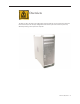
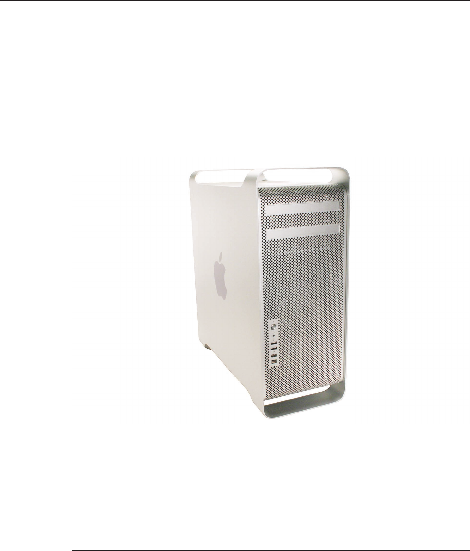
Overview The Mac Pro (8x) is the high-end configuration of the original Mac Pro and shares the same form factor. However, the Mac Pro (8x) configuration features two quad-core Intel Xeon processors, effectively making it an 8x-processor computer.
Identifying the Mac Pro (8x) To identify a Mac Pro (8x) computer, check the computer’s configuration label, which is located on the computer’s back panel directly below the video ports. Two numbers on the configuration label identify the computer as a Mac Pro (8x): • On the first line of the label, the EMC number is listed as “2138” • On the second line, the configuration description includes “3.
GSX Parts Because Mac Pro (8x) is a product configuration of the original Mac Pro, Mac Pro (8x) computers do not have serial numbers distinct from Mac Pro serial numbers. There is also no separate Mac Pro (8x) product pull-down list in GSX. When using a computer’s serial number to look up Mac Pro (8x) parts in GSX, be aware that you will receive a list of parts for both Mac Pro and Mac Pro (8x). Parts that are unique to Mac Pro (8x) will have “8x” included at the end of the part description.
Special Handling Instructions The Mac Pro (8x) configuration uses a special coating on the processor heatsink and processor to manage the temperature in the computer. To ensure proper handling and disposal of this material, please read the following information. Handling Instructions Use these guidelines when handling the Mac Pro (8x) processor heatsink and processor: General • • • • • Wear disposable nitrile or latex gloves when handling the processor heatsink and processor.
Krytox Thermal Grease • • To ensure a proper seal between the heatsink and processor, a bead of Krytox grease rims the gasket on the underside of the heatsink. Replacement heatsinks come with the grease already applied. Use the following guidelines for when to reapply Krytox grease to the heatsink. (Refer to “Processor Heatsinks” in the Take Apart chapter for detailed instructions on how to apply or clean off the grease.
Disposal Instructions Place all disposable materials used in removing or replacing a processor heatsink or processor inside the resealable plastic bag included with the replacement module. (Disposable materials include such items as protective gloves, alcohol wipes, lint-free cleaning cloths, Krytox grease and syringe, and heatsink gasket.) Pack this bag along with the failed module in the box that the replacement module came in, and return the box to Apple.
Service Source Take Apart Mac Pro (8x) © 2007 Apple Inc. All rights reserved.
General Information Orientation For most take-apart procedures, it is recommended that you lay the computer on its side before removing or installing the part. For proper operation, however, Apple recommends that the unit be run in the upright position. The computer should never be operated on its side with the access panel facing down.
Power Supply Fan Fully removing the power supply is a preliminary step for removing the power supply fan. The simplified procedure for removing the power supply therefore simplifies removal of the power supply fan. Processor Heatsink Cover When removing the heatsink cover, you no longer have to make room by removing the memory cage screws and sliding the memory cage toward the back of the computer. The heatsink cover is held in place with tabs and magnets and comes off easily without any tools.
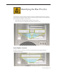
Opening the Computer Tools No tools are required for this procedure. Preliminary Steps 1. Shut down the computer. Warning: Always shut down the computer before opening it to avoid damaging its internal components or the components you are installing. Do not open the computer or attempt to install items inside it while it is on. 2. Wait 5 to 10 minutes to allow the computer’s internal components to cool. Warning: After you shut down the system, the internal components can be very hot.
Procedure 1. Hold the side access panel and lift the latch on the back of the computer. Warning: The edges of the access panel and the enclosure can be sharp. Be very careful when handling them. 2. Remove the access panel and place it on a flat surface covered by a soft, clean cloth. Replacement Note: Make sure the latch is in the up position before replacing the access panel. If the latch is down, the access panel will not seat correctly in the enclosure.
Hard Drives The Mac Pro (8x) computer can accommodate four serial ATA (SATA) 3 Gbps hard drives in its four internal hard drive bays. In most configurations, a single hard drive occupies the far left bay (bay 1). The hard drives must meet the following specifications: • Type: SATA 3 Gbps • Width: 3.9 inches (102 mm) • Depth: 5.7 inches (147 mm) • Height: 1.0 inch Tools The only tool required for this procedure is a Phillips #1 screwdriver.
Part Location Procedure 1. Make sure the latch on the back panel is up, so that the drives and carriers are unlocked. 2. Pull the hard drive out of the drive bay.
3. If you are replacing the hard drive with a new drive, remove the four screws that mount the drive to the carrier and mount the new drive in the carrier. Important: Hold the drive by its sides. Be careful not to touch the printed circuit board on the bottom of the drive. Replacement Note: Slide the carrier and drive over the guides and into the drive bay, until you feel the drive snap into place. Note: If you install a new (replacement) drive, format it by following these steps: 1.
Optical Drive Carrier and Optical Drives The Mac Pro (8x) computer can accommodate two optical drives in the optical drive bay. If the computer has only one optical drive, it is installed in the top position. Note: To eject the drives, use the following: • Top drive: Press the Eject key. • Bottom drive: Press the Option and Eject keys. Tools The only tool required for this procedure is a Phillips #1 screwdriver.
Procedure Removing the Optical Drive Carrier and Optical Drives 1. Make sure the latch on the back panel is up, so that the drives and carriers are unlocked. 2. Pull the optical drive carrier part way out of the computer.
3. Disconnect the power and ribbon cables from the optical drive(s) and remove the carrier. 4. • • If you are replacing the optical drive with a new optical drive, do the following: Remove the four mounting screws and remove the optical drive from the carrier. Use the four screws to mount the replacement drive in the carrier. Note: If you are adding a second drive to the carrier, use the four screws stored on the back of the drive carrier to secure the drive to the carrier.
Replacing the Optical Drive Carrier and Optical Drives Important: Use the original Apple cables that came with the computer when you install or replace the optical drives. If just one optical drive is installed, tuck the cables for the second drive out of the way. 1. Attach the power and ribbon cables to the back of the drive(s). Important: Attach the connector on the end of the optical drive ribbon cable and the connector in the middle of the optical drive power cable to the top drive.
Memory (FB-DIMMs) and Memory Riser Cards The Mac Pro (8x) computer has two memory riser cards with a total of 8 memory slots. On each card, the slots are arranged as two banks of two slots each. The computer comes with a minimum of 1 GB of memory, installed as a pair of 512 MB fully buffered, dual inline memory modules (FBDIMMs) in two of the DIMM slots. Additional DIMMs can be installed in the open DIMM slots, as illustrated below. Note: DIMMs must be installed in pairs of equal size from the same vendor.
DIMMs for Mac Pro (8x) must fit these specifications: • 667 MHz, FB-DIMMs • 72-bit wide, 240-pin modules • 36 devices maximum per DIMM • Error-correcting code (ECC) Memory from older Macintosh computers is not compatible with Mac Pro (8x). Important: For proper operation of Mac Pro (8x) computers, Apple recommends using only Apple-approved Mac Pro (8x) FB-DIMMs. Refer to GSX for Apple FB-DIMMs service part numbers. Tools No tools are required for this procedure.
Procedure 1. Holding the memory riser card by the two finger holes, pull it out of the memory cage and place the card DIMM side up on a soft, clean cloth. 2. Open the ejectors on the DIMM slot by pushing them out to the sides, and remove the DIMM from the riser card.
Replacement Note: Align the DIMM in the slot on the riser card and push both ends of the DIMM down until the ejectors snap back up into place. Warning: FB-DIMMs carry heatsinks on either side of the DIMM. Never attempt to remove the heatsinks from the DIMMs. Doing so could damage the DIMM.
PCI Express/Graphics Card The Mac Pro (8x) logic board includes one double-wide PCI Express graphics slot and three PCI Express expansion slots, for a total of four slots. The computer comes with a graphics card installed in slot 1. You can install additional PCI Express graphics and expansion cards in the remaining three PCI Express expansion slots. Important: Graphics cards from previous Power Mac G5 models are not compatible with Mac Pro (8x) models.
Part Location Procedure This procedure explains how to remove a standard card and a card that includes a booster cable. Before you can remove either type of card, however, you must first loosen the two captive screws that secure the PCI bracket to the enclosure and remove the bracket.
Warning: When removing or installing a card, handle it only by the edges. Do not touch its connectors or any of the components on the card. Lift the card straight out from the connector to remove it, and insert it straight into the connector to install it. Do not rock the card from side to side and don’t force the card into the slot. Once the replacement card is installed, pull on it gently to check that it is properly connected. Standard Card 1.
Card with Booster Cable 1. Disconnect the booster cable from the logic board. 2. Release the small locking clip at the front of the card’s logic board connector by pushing the clip up toward the media shelf. 3. Holding the card by the top corners, gently pull up the card and remove it from its expansion slot. 4. If you are replacing the booster cable with a new booster cable, disconnect the cable from the card.
Replacement Note: There are two logic board connectors for booster cables. Connect the booster cable for a card in PCI slot 1 to the lower connector. Connect the booster cable for a card in PCI slot 2 to the upper connector.
Power Supply Tools The only tools required for this procedure are a magnetized 2.5 mm hex wrench and a longhandled, magnetized Phillips #1 screwdriver.
Procedure 1. Using a Phillips screwdriver, remove the two mounting screws on the power supply cable cover located at the back of the optical drive bay. 2. Slide the cover toward the top of the enclosure, tilt it up until the two tabs on the cover clear the slots in the media shelf, and remove the cover from the enclosure. Replacement Note: Replace the cover at an angle so that the tabs engage with the slots in the media shelf. Then lower the cover into place.
3. Using a short-handled, magnetized 2.5 mm hex wrench, remove the four power supply mounting screws from the bottom of the media shelf. 4. Release the four power supply cables from their hook-and-loop fasteners on the enclosure. 5. Depress the locking latch on each cable connector and disconnect the four power supply cables from the four connectors on the power harness cable.
6. Slide the power supply toward the front of the computer. 7. Lift the power supply and cables out of the enclosure. Replacement Note: When replacing the power supply, be sure to slide it toward the back of the computer as far as possible. The power receptacle must align with the opening in the enclosure’s back panel and the four screw holes in the power supply must align with the screw holes in the media shelf.
Power Supply Fan Tools The only tools required for this procedure are needlenose pliers and scissors or wire cutters (optional) Preliminary Steps Before you begin, open the computer, lay it on its side with the access side facing up, and remove the following: • Hard drives and hard drive carriers in drive bays 3 and 4 • Optical drive carrier and optical drives • Any PCI Express cards that block access to the power supply mounting screws • Power supply Part Location Mac Pro (8x) Take Apart — Power Supply
Procedure 1. Disconnect the power supply fan cable from the logic board and thread the cable through the opening in the media shelf. 2. Using needlenose pliers, pull out the four grommets that mount the power supply fan to the media shelf divider. Note: You may find scissors or wire cutters useful in snipping off the grommet heads.
3. Rotate the fan and remove it from the enclosure.
Replacing the Power Supply Fan 1. Place the power supply fan in the media shelf and thread the fan’s cable through the opening in the shelf. 2. Connect the cable to the logic board. 3. Rotate the fan into place flush against the media shelf divider. Make sure the back of the fan faces the divider, as illustrated.
Note: To secure the power supply fan to the divider, use the long-tailed grommets enclosed with the replacement fan. 4. Thread the first grommet, tail first, through one of the four grommet holes in the divider and on through the corresponding grommet hole in the fan bracket. Then pull to secure the grommet and detach the excess threading tail. (The tail is notched to break off at the correct place.) 5. Repeat for the other three grommets.
AirPort Extreme Card Important: The computer enclosure includes AirPort antenna wires and a Bluetooth antenna wire. The Bluetooth antenna wire looks similar to the AirPort antenna wires, except that it includes a “BT” label. For proper operation, be careful not to connect the Bluetooth antenna wire to the AirPort card or any AirPort antenna wire to the Bluetooth card. Note: You may connect the AirPort antenna wires to either AirPort card connector.
Procedure 1. Remove the two AirPort Extreme card mounting screws. 2. Lift the AirPort Extreme card a short distance from the logic board. 3. Disconnect the AirPort antenna wires from the card.
4. Remove the card from the enclosure. Replacement Note: To replace the AirPort Extreme card, do the following: • Connect the antenna wires to the card. Important: Be sure to connect the wires that are marked 1 and 3 to the card; the antenna wire that is marked 2 should be taped out of the way. • Insert the card into its logic board connector at an angle, as illustrated. • Lower the screw end of the card down to the standoffs on the logic board and replace the two mounting screws.
Bluetooth Card Important: The computer enclosure includes one Bluetooth antenna wire, which looks similar to the AirPort antenna wires, except that it includes a “BT” label. If the label is missing, you can also identify the Bluetooth cable by its location; it is the cable that runs to the back of the computer. For proper operation, be careful not to connect the Bluetooth antenna wire to the AirPort card or any AirPort antenna wire to the Bluetooth card.
Procedure 1. Remove the two Bluetooth card mounting screws. 2. Lift the Bluetooth card a short distance from the logic board. 3. Disconnect the Bluetooth antenna wire from the card. 4. Remove the card from the enclosure. Note: If you are not replacing the Bluetooth card, cover the connector on the Bluetooth antenna wire with Kapton or other non-conductive tape to prevent it from shorting out components on the logic board.
Battery Tools No tools are required for this procedure. You may, however, find a flat-blade screwdriver useful in removing the battery from its holder. Preliminary Steps Before you begin, open the computer, lay it on its side with the access side facing up, and remove any PCI Express cards that block access to the battery.
Procedure 1. Slide the battery out from underneath the battery holder’s metal clip. 2. Remove the battery from its holder. Replacement Note: Insert the new battery into the holder, making sure the battery’s positive symbol (+) faces up. Warning: Installing the battery incorrectly may cause an explosion. Be sure the battery’s positive and negative sides are correctly oriented in the holder. Use only the same type of battery or an equivalent recommended by the manufacturer of the original.
Processor Heatsink Cover Tools No tools are required for this procedure. Preliminary Steps Before you begin, open the computer, lay it on its side with the access side facing up, and remove any 12-inch PCI Express cards.
Procedure Note: The heatsink cover is held in place by a number of tabs and magnets on the underside of the cover. You must release the tabs before you can remove the cover from the enclosure. 1. Place the fingers of one hand under the lip of the heatsink cover nearest the logic board. Lift the lip slightly toward the media shelf to release the tabs and magnets under the top face of the cover. 2.
Replacement Note: When reinstalling the processor heatsink cover, make sure the tabs on the underside of the cover align with the slots directly below them. (The slots are on the front fan and memory cage on either side of the heatsink cover.
Front Fan Assembly Tools The only tool required for this procedure is a long-handled, magnetized #1 Phillips screwdriver.
Procedure 1. Using a long-handled, magnetized #1 Phillips screwdriver, remove the screw at the top rear of the front fan assembly that mounts the assembly to the logic board. 2. Remove the second Phillips screw at the bottom front of the assembly.
3. Place one hand on each end of the fan, lift straight up, and remove the fan from the enclosure. Replacement Note: Before re-installing the front fan assembly in the enclosure, make sure that the fan cables are routed correctly in the fan channel.
Replacement Note: Make sure all AirPort and Bluetooth antenna wires are out of the way before lowering the fan assembly onto the logic board. Replacement Note: When lowering the front fan into the enclosure, slide the guide on the base of the fan assembly into the channel on the speaker assembly.
Also make sure the latch on the inside top left edge of the fan assembly engages with the slot on the inside lip of the enclosure. Then press down until you hear the fan click into place in the connector on the logic board.
Mac Pro RAID Card and Battery Note: If a Mac Pro RAID Card is installed in a Mac Pro (8x), the standard iPass cable routing has been changed so that the cable connects to the card, rather than to the logic board. Tools The only tool required for this procedure is a Phillips #1 screwdriver. You might also find a small flat-blade screwdriver helpful in releasaing the iPass cable connector.
Procedure 1. If you have not already done so, loosen the two captive screws that secure the PCI bracket to the enclosure and remove the bracket. Warning: When removing or installing a card, handle it only by the edges. Do not touch its connectors or any of the components on the card. Lift the card straight out from the connector to remove it, and insert it straight into the connector to install it. Do not rock the card from side to side and don’t force the card into the slot.
2. Release the small locking clip at the front of the card’s logic board connector by pushing the clip up toward the media shelf. 3. Holding the card by the top corners, gently pull up the card and remove it from its expansion slot. Note: The Mac Pro RAID Card must always be installed in slot 4.
4. Disconnect iPass cable from the Mac Pro RAID Card. Note: You may find it helpful to use a small, flat-blade screwdriver to release the cable connector. Depress the rear edge of the silver-colored latch on top of the connector. 5. Remove the card from the enclosure.
6. The Mac Pro RAID Card includes its own battery. If you are replacing the battery on the card, do the following: • Disconnect the battery cable from the card. • Remove the four mounting screws and lift the battery from the card. Important: Do not drop, disassemble, crush, incinerate, or expose the battery to temperatures above 212° F (100° C). Stop using the battery if it appears damaged in any way. Replace the battery only with an Apple-authorized battery for this computer.
Replacing the Mac Pro RAID Card 1. Connect the iPass cable to the Mac Pro RAID Card. 2. Align the card’s connector with expansion slot 4 and press until the connector is inserted all the way into the slot. Make sure the card also engages slot 4 in the PCI card guide. Note: • Don’t rock the card from side to side; instead, press the card straight into the slot. • Don’t force the card. If you meet a lot of resistance, pull the card out.
Memory Cage with Rear Fan Tools The only tools required for this procedure are a long-handled, magnetized #1 Phillips screwdriver and a short-handled, magnetized jeweler’s #1 Phillips screwdriver or right-angle, magnetized #1 Phillips screwdriver.
Procedure 1. Disconnect the rear fan cable from the logic board. 2. Using a long-handled, magnetized #1 Phillips screwdriver, remove the two long screws that mount the memory cage to the logic board. 3. Using a short-handled, magnetized jeweler’s #1 Phillips screwdriver or right-angle, magnetized #1 Phillips screwdriver, carefully remove the two short screws that mount the memory cage to the bottom panel of the enclosure.
Note: To remove the memory cage and fan, you must first slide the fan partway into the cage. The fan is held in place by two latches, which you must release before sliding the fan. 4. Using your forefinger, reach below the fan and release the latch nearest the logic board. 5. Using a flat-blade screwdriver, release the second latch nearest the front of the computer. 6. Slide the rear fan into the memory cage.
7. Slide the memory cage and fan toward the power supply far enough that the cage clears the bottom edge of the enclosure. Then lift the memory cage and fan out of the enclosure. Replacement Note: If you are installing a new fan in the memory cage assembly, position the fan as illustrated. Important: Before you install the cage in the enclosure, the fan should always be inserted partway into the cage.
Replacement Note: Before installing the memory cage and fan, make sure all logic board cables below the cage are out of the way so that the cage sits properly and the cables are not pinched or damaged when you tighten the screws. Replacement Note: To install the memory cage and fan, maneuver the cage into position in the enclosure. Replace one long mounting screw. Then slide the fan toward the back panel, until you hear it snap into place.
Processor Heatsinks The Mac Pro (8x) computer uses a special coating on the processor heatsink and processor to manage the temperature in the computer. The silver-colored coating comes applied to the underside of the heatsink and the top of the processor. IMPORTANT: If you need to install a new heatsink or processor, reassemble the unit while you are waiting for the new part to arrive.
Part Location Procedure 1. Disconnect the 2-pin cable for the upper processor (CPU A) heatsink from the logic board.
2. Using a long-handled, magnetized 3 mm flathead hex screwdriver, loosen the four captive mounting screws for the upper processor heatsink in the order indicated below. 3. Lift the heatsink straight up and out of the enclosure. 4. Disconnect the cable connector for the lower processor (CPU B) heatsink.
5. Using a long-handled, magnetized 3 mm flathead hex screwdriver, loosen the four captive mounting screws for the lower processor heatsink in the order indicated below. 6. Carefully tilt the heatsink so that it clears the bottom lip of the enclosure and then lift the heatsink out of the computer. IMPORTANT: Remember that you cannot leave the heatsink separated from either the upper or lower processor for more than 30 minutes.
Visual Inspection of Heatsink Gasket Before installing a new or existing heatsink, check that the gasket that surrounds the silvercolored coating on the underside of the heatsink is in good condition, as illustrated below. Replace the gasket if it shows obvious damage, such as cracks, folds, and broken-off surfaces, or if it is dislocated from the heatsink. The gasket is available through GSX as part of the Mac Pro Grease Kit, part number 076-1258.
• • Using the pre-measured syringe of Krytox grease from the kit, evenly apply a bead of grease around the full perimeter of the heatsink gasket. Apply the full syringe of grease to the gasket. Warning: Do not apply more grease than recommended. The grease must not overflow the heatsink and come in contact with the processor connector. Do not apply any grease to the processor. Installing New Processors Do not apply new grease to either the heatsink or the processor.
Replacement Instructions for Heatsink IMPORTANT: If you are installing a new heatsink, do not remove it from its Note: If you are re-installing an existing heatsink, go directly to step 1 below. If you are installing a replacement heatsink, first do the following: • Unpack the new heatsink according to the instructions included in the parts box. • Remove the protective cap covering the underside of the heatsink and transfer it to the heatsink you are returning to Apple.
• If you are replacing the lower processor heatsink with a new heatsink, install the bumper included in the parts box on the side of the heatsink. 1. Visually inspect the gasket on the underside of the heatsink. See “Visual Inspection of Heatsink Gasket” earlier in this procedure. 2. Carefully align the posts on the lower heatsink with the mounting holes in the logic board, and lower the heatsink onto the processor. 3. Lightly tighten the heatsink mounting screws in the order indicated below. 4.
Disposal Instructions Place all disposable materials used in removing or replacing a processor heatsink or processor inside the resealable plastic bag included with the replacement module. (Disposable materials include such items as protective gloves, alcohol wipes, lint-free cleaning cloths, Krytox grease and syringe, suction pipette, and heatsink gasket.) Pack this bag along with the failed module in the box that the replacement module came in, and return the box to Apple.
Processors The Mac Pro (8x) computer uses a special coating on the processor heatsink and processor to manage the temperature in the computer. The silver-colored coating comes applied to the underside of the heatsink and the top of the processor. IMPORTANT: If you need to install a new heatsink or processor, reassemble the unit while you are waiting for the new part to arrive. Use the following guidelines when handling the processor heatsink and/or processor: • Wear disposable nitrile or latex gloves.
Tools No tools are required for this procedure. However, you may find a flat-blade screwdriver helpful in releasing the processor holder latch.
Procedure Note: This procedure illustrates how to remove the lower processor (CPU B). The instructions are the same for removing the upper processor (CPU A). You may, however, want to use a flat-blade screwdriver to release the latch on the upper processor. 1. Release the latch on the metal processor holder. Note: You may want to use a flat-blade screwdriver to release the latch on the upper processor. 2. Rotate the top of the holder to the open position.
3. Placing a finger in the notch at the front of the processor holder, pry up the processor and lift it out of the holder. Important: When removing or installing a processor, always hold the processor by the edges. Be extremely careful not to touch the gold pins on the bottom of the processor, as this type of connector is very sensitive to contamination. Also be careful not to touch the gold pins in the processor socket on the logic board.
IMPORTANT: If you are installing a new processor, do not remove it from its vacuum-packed bag until you are ready to install it. Be sure to follow all directions for unpacking the processor that are included in its packing box. Replacement Note: Before installing a new, replacement processor, remove the protective container covering the new processor. Transfer the container to the original processor before returning it to Apple.
Speaker Assembly Tools The only tools required for this procedure are a magnetized #1 Phillips screwdriver and a magnetized jeweler’s #0 Phillips screwdriver.
Procedure 1. Remove the three speaker assembly mounting screws. 2. Carefully pivot the speaker assembly a short distance away from the enclosure. 3. Disconnect the speaker assembly cable from the logic board. 4. Remove the speaker assembly from the computer.
5. If you are replacing the speaker in the assembly bracket, do the following: • Slide the speaker cable through the opening in the speaker bracket. • Using a magnetized jeweler’s #0 Phillips screwdriver, remove the four mounting screws. 6. Remove the speaker and cable from the bracket.
USB Cable Tools No tools are required for this procedure.
Procedure 1. Disconnect the USB cable from connector J201 on the front panel board. 2. Disconnect the USB cable from connector J2D1 on the logic board. 3. Remove the cable from the enclosure.
Logic Board Note: Every time you remove the logic board, you must also remove the two processor heatsinks. See special instructions for handling the heatsinks in “Processor Heatsinks” in the Take Apart chapter. Tools The only tool required for this procedure is a magnetized Phillips #1 screwdriver.
Part Location Mac Pro (8x) Take Apart — Logic Board 89
Procedure 1. To keep them out of the way, temporarily tape the antenna cables to the bottom of the media shelf. Important: Be sure to disconnect all cables from the logic board before you remove the logic board mounting screws.
2. Starting at the back panel side of the logic board and working clockwise around the board, disconnect all cables from the logic board. Note: There are 14 cables you will be disconnecting from the logic board.
3. Using a magnetized #1 Phillips screwdriver, remove the 11 black logic board mounting screws.
4. Slide the logic board back a short distance from the port openings in the back panel. Make sure the ports clear the openings. 5. Tilt the top edge of the logic board up and maneuver the board out of the enclosure.
Replacement Note: Before replacing the logic board, check the underside of the board to be sure that all bumpers are in place. Replace any missing bumpers. Replacement Note: If you are replacing the logic board with a new logic board, do the following: • Remove the protective caps from the new logic board’s processor holders and transfer the caps on the original logic board’s processor holders. Note that logic boards returned to Apple without the protective caps may be rejected.
• • Transfer the processors to the new board: Refer to the “Processors” topic in this chapter. You must also transfer the back ports EMI shield to the new board. Replacement Note: To replace the logic board, tilt it as shown and lower it into the enclosure. Note: Unlike in earlier Power Mac G5 computers, replacing a logic board in Mac Pro (8x) does not require running Apple Service Diagnostic for thermal calibration.
Front Panel Board Tools The only tool required for this procedure is a long-handled, magnetized Phillips #1 screwdriver.
Procedure 1. Disconnect the optical drive ribbon cable from the logic board and move the cable out of the way.
2.
3. Using a magnetized #1 Phillips screwdriver, remove the five front panel board mounting screws. 4. Lift the front panel board out of the computer. Note: If you are replacing the front panel board with a new front panel board, separate the EMI shield from the back of the board and transfer it to the new front panel board.
Power Button Tools The only tool required for this procedure is a jeweler’s flat-blade screwdriver.
Procedure 1. Disconnect the optical drive ribbon cable from the logic board and move the cable out of the way. 2. Disconnect the front panel board power cable from the front panel board and move it out of the way. 3. Disconnect the power button cable from the front panel board. 4. Lay the computer so that the front panel is facing down.
5. Remove the black rubber cap that covers the power button LED. 6. Using a jeweler’s flat-blade screwdriver, pry up the metal C-ring that secures the power button board. 7. Lift up and remove the power button board.
8. Remove the metal activation ring that lies below the power button board. 9. Remove the power button from the enclosure.
AirPort Antenna Board with Cables The AirPort Extreme antenna cables are part of the AirPort antenna board assembly. To remove or replace the cables, you must replace the antenna board assembly Tools The only tools required for this procedure are a jeweler’s flat-blade screwdriver and a magnetized jeweler’s Phillips #0 screwdriver.
Part Location Procedure 1. Place the computer so that the bottom panel is facing you. 2. Remove the tape holding the antenna cables to the enclosure. 3. Using a jeweler’s flat-blade screwdriver, pry open the three latches on the antenna cables ferrite bead and remove the bead from the cables.
4. Using the jeweler’s flat-blade screwdriver, carefully pry up the rectangular plastic plate on the bottom panel. 5. Using a jeweler’s #0 Phillips screwdriver, remove the four antenna board mounting screws.
6. Tilt the antenna board away from the back panel a short distance. 7. Feed each antenna cable separately out through the small opening in the bottom panel. 8. Remove the antenna board and cables from the enclosure.
Optical Drive Power Cable Tools The only tool required for this procedure is a magnetized #1 Phillips screwdriver.
Procedure 1. Using a magnetized #1 Phillips screwdriver, remove the two mounting screws on the hard drive connector for drive bay 1 and move the connector out of the way. 2. Unwind the tape that holds the optical drive data cable to the optical drive power cable. 3. Disconnect the optical drive power cable from the logic board. 4. Insert the logic board end of the power cable into the opening in the media shelf at hard drive bay 1 and remove the cable from the enclosure.
Mac Pro (8x) Take Apart — Optical Drive Power Cable 110
Optical Drive Data (Ribbon) Cable Tools The only tool required for this procedure is a magnetized #1 Phillips screwdriver.
Procedure 1. Using a magnetized #1 Phillips screwdriver, remove the two mounting screws on the hard drive connector for drive bay 1 and move the connector out of the way. 2. Unwind the tape that holds the optical drive data cable to the optical drive power cable. 3. Disconnect the optical drive data cable from the logic board. 4. Insert the cable into the opening in the media shelf at hard drive bay 1 and remove the cable from the enclosure.
Ambient Board Note: The ambient board is attached to the enclosure with adhesive. Once you remove the ambient board, you may have to apply new adhesive before reattaching the same ambient board. Replacement ambient boards come with adhesive already in place. Tools The only tools required for this procedure are a jeweler’s flat-blade screwdriver. Preliminary Steps Before you begin, open the computer, lay it on its side with the access side facing up, and remove the optical drive carrier and optical drives.
Procedure 1. Locate the ambient board on the inside left corner of the top panel, above the optical drive carrier. 2. Disconnect the ambient board cable from the ambient board. 3. Using a jeweler’s flat-blade screwdriver, carefully pry the board from the enclosure. Important: After you replace the ambient board, you must reset the System Management Controller. Refer to “Resetting the Logic Board” in the Troubleshooting chapter.
Ambient Board Cable Tools The only tool required for this procedure is a magnetized #1 Phillips screwdriver.
Procedure 1. Remove any tape holding the ambient board cable to the enclosure. 2. Disconnect the ambient board cable from the ambient board and logic board. 3. Using a magnetized #1 Phillips screwdriver, remove the two mounting screws on the hard drive connector for drive bay 1 and move the connector out of the way. 4. Route the ambient board cable out through the opening in the media shelf and remove the cable from the enclosure.
Bluetooth Antenna Board and Cable The Bluetooth antenna cable is part of the Bluetooth antenna board assembly. To remove or replace the cable, you must replace the antenna board assembly. Tools The only tool required for this procedure is a jeweler’s flat-blade screwdriver.
Part Location Procedure 1. Insert a jeweler’s flat-blade screwdriver into the notch on either side of the Bluetooth antenna cage and carefully pry up the cage from the enclosure.
2. Remove the tape holding the Bluetooth antenna cable to the enclosure. 3. Remove the antenna board and antenna cable from the enclosure.
Hard Drive Cable Harness The hard drive cable harness consists of the hard drive data cable and the hard drive power cable taped together. The cables are not available as separate service parts. Tools The only tools required for this procedure are a long-handled, magnetized #1 Phillips screwdriver.
Procedure 1. Disconnect the hard drive data and power cable connectors from the logic board. 2. Using a long-handled, magnetized #1 Phillips screwdriver, remove the two screws holding the hard drive cable harness connector to the bracket below hard drive bay 1. 3. Remove the connector from the bracket. 4. Repeat for the other three connectors below hard drive bays 2, 3, and 4. 5. Remove the hard drive cable harness from the enclosure.
Hard Drive Temperature Sensor Cable The hard drive temperature sensor cable is a wire harness with four connectors, one for each hard drive temperature sensor. Be careful not to catch or damage any of the wires when removing the harness from the enclosure. Tools No tools are required for this procedure.
Procedure 1. Disconnect the hard drive temperature sensor cable from the logic board. 2. Disconnect the four connectors on the hard drive temperature sensor cable from the four hard drive temperature sensors. 3. Remove the hard drive temperature sensor cable from the enclosure. Replacement Note: The connectors on the hard drive temperature sensor cable are labeled with HDD1, HDD2, HDD3, and HDD4 to indicate the connector that belongs to each temperature sensor.
Hard Drive Temperature Sensor There are four hard drive temperature sensors, one for each hard drive. This procedure explains how to remove the sensor for the hard drive in drive bay 1. The procedure for removing the other three sensors is similar, except that the only part you need to remove before beginning the procedure is the hard drive directly over the sensor. Tools The only tools required for this procedure are a mirror and a black stick or a flat-blade screwdriver.
Part Location Procedure 1. Disconnect the sensor cable for the hard drive in bay 1 and move the cable out of the way.
2. Using a mirror, locate the two round black nubs on the bottom of the hard drive sensor below hard drive bay 1. 3. Using a black stick or a flat-blade screwdriver, press up on the nubs and remove the sensor from the enclosure.
Power Cable Harness The power cable harness consists of the following cables: • Power supply PS1 cable • Power supply PS2 cable • Power supply PS3 cable • Power supply PS4 control cable • Front panel board power cable • Front panel board audio cable • Front panel board FireWire 800 cable Tools No tools are required for this procedure.
Part Location Procedure 1. Disconnect the power cable harness connectors from the logic board.
2. Using a Phillips screwdriver, remove the two mounting screws on the power supply cable cover located at the back of the optical drive bay. 3. Slide the cover toward the top of the enclosure, tilt it up until the two tabs on the cover clear the slots in the media shelf, and remove the cover from the enclosure. Replacement Note: Replace the cover at an angle so that the tabs engage with the slots in the media shelf. Then lower the cover into place.
4. Release the four power supply cables from their hook-and-loop fasteners on the enclosure. 5. Depress the locking latch on each cable connector and disconnect the four power supply cables from the four connectors on the power harness cable. 6. Slip the four connectors out through the opening in the media shelf, removing them one at a time.
7. Untape the power harness cable from the enclosure. 8. Remove the power harness cable from its routing along the edge of the logic board, over the speaker assembly, and along the bottom lip of the enclosure. 9. Remove the power harness cable from the enclosure.
Service Source Troubleshooting Mac Pro (8x) © 2007 Apple Inc. All rights reserved.
General Information Memory The Mac Pro (8x) computer has two memory cards with a total of 8 memory slots. On each card, the slots are arranged as two banks of two slots each. The computer comes with a minimum of 1 GB of memory, installed as a pair of 512 MB fully buffered, dual inline memory modules (FBDIMMs) in two of the DIMM slots. Additional DIMMs can be installed in the open DIMM slots, as illustrated below. Note: DIMMs must be installed in pairs of equal size from the same vendor.
DIMMs for Mac Pro (8x) must fit these specifications: • 667 MHz, FB-DIMMs • 72-bit wide, 240-pin modules • 36 devices maximum per DIMM • Error-correcting code (ECC) Important: For proper operation of Mac Pro (8x) computers, Apple recommends using only Apple-approved Mac Pro (8x) FB-DIMMs. Refer to GSX for Apple FB-DIMMs service part numbers. PCI Express Cards The Mac Pro (8x) logic board includes one double-wide PCI Express graphics slot and three PCI Express expansion slots, for a total of four slots.
Mac Pro (8x) Troubleshooting — General Information 135 922-7684 922-7686 922-8059 Optical Drive Power Optical Drive IDE Power Supply PS #1 922-8060 922-8061 922-8030 922-7690 922-7692 922-7691 922-7693 922-7731 Power Supply PS #2 Power Supply PS #3 Power Supply Control PS # 4 Front Panel Board Power Front Panel Board Audio Front Panel Board FireWire800 Front Panel Board USB Intake Ambient Temperature Sensor 400 150 695 865 860 1083 273 469 1033 586 559 610 922-7730 HDD SAT
Cable Connector Locations Use the diagram below to find the location of the internal cable connectors on the logic board. A B C D E F G H J K 9 9 8 8 7 7 6 6 5 5 4 4 3 3 2 2 1 1 A B C D E F G H J K Thermal Calibration Unlike in earlier Power Mac G5 computers, replacing a processor in a Mac Pro (8x) computer does not require running Apple Service Diagnostic for thermal calibration.
Resetting the Logic Board System Management Controller (SMC) Reset The System Management Controller (SMC) is a chip on the logic board that controls all power functions for the computer. If the computer is experiencing any power issue, resetting the SMC may resolve it.
Real Time Clock (RTC) Reset The Real Time Clock (RTC) is a chip on the logic board that controls the date and time functions of the computer. If the computer is experiencing an issue booting, resetting the RTC may resolve it. Follow these steps to reset the RTC: 1. From the Apple menu, choose Shut Down (or if the computer is not responding, hold the power button until it turns off). 2. Unplug the AC power cord. 3. Remove the battery for at least 20 seconds.
Diagnostic LEDs The Mac Pro (8x) logic board includes a set of LEDs to help service providers troubleshoot the computer. The LEDs are located toward the rear of the logic board, under the memory cage, next to PCI card slot 1. You can view these LEDs by removing the computer’s side access panel and looking through the memory cage to the logic board below. LEDs 2, 3, 4, and 5 are normally off and will automatically illuminate if an error occurs.
Use the following table to interpret the LEDs.
LED 2 CPU B (Lower Processor) Error LED 3 CPU A (Upper Processor) Error Normally off. These LEDs come on if an error occurs or if the BootROM is corrupted. They do not depend on the DIAG_LED button being pressed. Related symptoms include no video or the computer is hung up. If the BootROM is corrupted, the optical drive tray should eject, prompting for the insertion of a recovery disc to restore the BootROM. Troubleshooting: • With the computer booted, up press the SYS_RST switch.
• Try swapping CPU A and CPU B locations. If the CPU Error LED follows the CPU, replace that CPU. LED 6 GPU Present Normally on when DIAG_LED button is pressed. If this LED is on, it indicates there is a graphics card installed and recognized by the computer. It does not indicate that the graphics card is fully functional. Some graphics cards require additional power to function, which is available from connectors on the logic board.
Interface (EFI) operations and the operating system is now in control. Troubleshooting: • Check that LED 7 Power On LED is on. • Check that LEDs 2, 3, 4, and 5 are off. • Try removing any added hardware. • Try removing any added DIMMs. Memory Riser Card Diagnostic LEDs Both of the memory riser cards include diagnostic LEDs for each DIMM. Each of the LEDs will light if it detects an issue with the corresponding installed DIMM.
• Replace the video card. Ext_Power LED Normally off, this LED lights up if the auxiliary power isn’t being supplied. Troubleshooting: • Make sure the card’s auxiliary booster power cable is connected (if there is one). • Check connections from the power supply to the logic board. • Try a different auxiliary power cable. • Try a different video card. • Replace the video card. Power Supply Verification To power on, the computer’s logic board requires “trickle” power.
the Boot ROM, and SMC updates update the System Management Controller firmware. The SMC manages fans and other environmental parameters that are independent of the Boot ROM. Firmware symptoms can be easily mistaken for hardware issues (e.g., overheating issues, fan noise issues, etc.). Always check both EFI and SMC firmware versions and update if necessary before replacing any hardware components in the Mac Pro (8x).
Processor Heatsink and Processor Visual Inspection Instructions The Mac Pro (8x) uses a special coating on the processor heatsink and processor to manage the temperature in the computer. Before installing a new or existing heatsink or processor, always make a visual inspection of the part. Specifically, check the application of the silver-colored coating on the underside of the heatsink and the top of the processor. In addition, check the condition of the gasket that surrounds the coating on the heatsink.
Unacceptable examples The following are examples of unacceptable applications of the coating. Return new parts or replace existing parts that exhibit similar applications. Void I Void II Splash Void I: The silver-colored coating shows missing areas of within the normal coated area. Void II: The silver-colored coating shows missing areas along the edge of the coated area. Splash: The silver-colored coating extends beyond the normal coated area.
To remove the particles, use the suction pipette that comes with the replacement heatsink and processor. (The pipette is also available through GSX as part of the Mac Pro Grease Kit, part number 076-1258.) Depress the bulb end of the pipette, place the other end over the particle, and release the bulb. The particle will be suctioned into the pipette. Once you have removed all stray particles, place the pipette inside the resealable bag included with the replacement part.
Symptom Charts How to Use the Symptom Charts The Symptom Charts included in this chapter will help you diagnose specific symptoms related to the product. Because cures are listed on the charts in the order of most likely solution, try the cures in the order presented. Verify whether or not the product continues to exhibit the symptom. If the symptom persists, try the next cure. Note: If a cure instructs you to replace a module, reinstall the original module before you proceed to the next cure.
8. Verify that processors’ mounting clamps are properly tightened. 9. Test whether the front panel board or power button is at fault. Remove the installed front panel board and test with a known-good front panel board. 10. Replace front panel board. 11. Replace power button. 12. Replace power supply. 13. Replace logic board. Power-on LED illuminates when pressed in, but goes out when button is released, there is no boot tone or video, but you can hear a small click 1.
4. Check diagnostic LED 2 and/or LED 3 for processor connection 5. If only one of the CPU Error LEDs (LED 2 or 3) comes on, try swapping the processors. If the Error LED follows the processor to the other processor location, replace that processor. 6. Replace logic board Power-on LED illuminates when power button is pressed, fans spin, and boot tone chimes, but there is no video 1. Verify display is properly connected and powered on. 2.
Fans Individual fan failure 1. Verify fan is properly connected. 2. Verify all other fans are working properly. If all fans seem to have failed, the problem is most likely not the fans. Reset the logic board to see if this resolves this problem. 3. Replace fan 4. Replace logic board Fans run at high speed (computer may shut down or may just hang and not shut down as a result) 1. Check for proper ventilation around the exterior of the computer. 2.
3. Check for proper ventilation around the exterior of the computer. 4. Remove the computer’s side access panel and observe the diagnostic LEDs, specifically LED 4 and LED 5 (the CPU A and B Overtemp LEDs). Refer to “Diagnostic LEDs” in this chapter for more information on how to locate and interpret these LEDs. If either of these LEDs is flashing, this may indicate an initial processor over temperature condition.
Bluetooth Card Bluetooth Card does not appear to function and is not recognized by System Profiler 1. Start up the computer from a known-good volume (such as an external hard drive) with Bluetooth driver software installed, to isolate the issue to software or hardware. If the computer seems to perform adequately when booted in this way, troubleshoot as a software issue. If the computer continues to exhibit the issue, follow the steps below. 2. Reseat card and antenna cable connected to card 3.
Front Panel FireWire port 1. Reset SMC. 2. Reseat front panel board cables 3. Replace front panel board cables 4. Reseat front panel board 5. Replace front panel board 6. Replace logic board Rear FireWire port 1. Reset SMC. 2. Replace logic board Front Panel USB 2.0 port 1. Reseat front panel board cables 2. Replace front panel board cables 3. Reseat front panel board 4. Replace front panel board 5. Replace logic board Rear Panel USB 2.
Audio IO (front headphones) 1. Start up the computer from a known-good volume (such as its Installation disc or an external hard drive), to isolate the issue to software or hardware. If the computer seems to perform adequately when booted in this way, troubleshoot as a software issue. If the computer continues to exhibit the issue, follow the steps below. 2. Reset PRAM 3. Reseat front panel board 4. Replace front panel board 5.
Service Source Upgrades Mac Pro (8x) © 2007 Apple Inc. All rights reserved.
AirPort Extreme Card Important: The computer enclosure includes AirPort antenna wires and a Bluetooth antenna wire. The Bluetooth antenna wire looks similar to the AirPort antenna wires, except that it includes a “BT” label. For proper operation, be careful not to connect the Bluetooth antenna wire to the AirPort card or any AirPort antenna wire to the Bluetooth card. Note: You may connect the AirPort antenna wires to either AirPort card connector.
Procedure 1. Connect the AirPort antenna wires to the connectors on the card. Important: Be sure to connect the wires that are marked 1 and 3 to the card; the antenna wire that is marked 2 should be taped out of the way. 2. Insert the AirPort Extreme card into its logic board connector at an angle, as illustrated. Then lower the screw end of the card down to the standoffs on the logic board.
3. Install the two AirPort Extreme card mounting screws.
Bluetooth Card Important: The computer enclosure includes one Bluetooth antenna wire, which looks similar to the AirPort antenna wires, except that it includes a “BT” label. If the label is missing, you can also identify the Bluetooth cable by its location; it is the cable that runs to the back of the computer. For proper operation, be careful not to connect the Bluetooth antenna wire to the AirPort card or any AirPort antenna wire to the Bluetooth card.
Procedure 1. Connect the Bluetooth antenna wire to the connector on the Bluetooth card. 2. Lower the card onto the Bluetooth connector on the logic board. 3. Install the two Bluetooth card mounting screws.
PCI Express/Graphics Card The Mac Pro (8x) logic board includes one double-wide PCI Express graphics slot and three PCI Express expansion slots, for a total of four slots. The computer comes with a graphics card installed in slot 1. You can install additional PCI Express graphics and expansion cards in the remaining three PCI Express expansion slots. Important: Combined maximum power consumption for all four PCI Express slots must not exceed 300 W.
Part Location Procedure This procedure explains how to install a standard card and a card that includes a booster cable. Before you can install either type of card, however, you must first loosen the two captive screws that secure the PCI bracket to the enclosure and remove the bracket. You must also remove the port cover for the PCI slot where you are installing the new card.
Warning: When installing or removing a card, handle it only by the edges. Do not touch its connectors or any of the components on the card. Standard Card 1. Align the card’s connector with the expansion slot and press until the connector is inserted all the way into the slot. If you’re installing a 12-inch card, make sure the card engages the appropriate slot in the PCI card guide. • Don’t rock the card from side to side; instead, press the card straight down into the slot. • Don’t force the card.
Card with Booster Cable 1. Connect the booster cable to the card. 2. Holding the card by the top corners, insert it straight down into its expansion slot. 3. Connect the booster cable to the logic board. Note: There are two logic board connectors for booster cables. Connect the booster cable for a card in PCI slot 1 to the connector that is closest to the heatsink cover. Connect the booster cable for a card in PCI slot 2 to the connector closest to the media shelf.
Service Source Views Mac Pro (8x) © 2007 Apple Inc. All rights reserved.
Exploded Views Exploded View 1 Access Door 922-8004 Ambient Board 922-7732 Optical Drive Carrier 922-7729 Power Supply Fan 076-1232 Optical Drive 661-4276 Hard Drive 250 GB 661-4273 500 GB 661-4274 750 GB 661-4275 Power Supply 661-4309 FB-DIMMS 512 MB 661-4312 1 GB 661-4315 2 GB 661-4329 PS Cable Cover 922-8005 Memory Riser Card 922-7695 Hard Drive Carrier 922-7728 Processor Heatsink Cover 922-8001 Front Fan 922-7999 Heatsink 661-4332 Bluetooth Card 922-7289 AirPort Extreme Card 661-4060 Power Butto
Exploded View 2 Hard Drive Harness Cable 922-7682 Hard Drive Temperature Sensor Cable 922-7730 Power Supply PS#1 Cable 922-8059 Power Supply PS#2 Cable 922-8060 Power Supply PS#3 922-8061 Power Supply Control PS#4 922-8030 Optical Drive Power Cable 922-7684 Optical Drive Data Cable 922-7686 Front Panel Board Power Cable 922-7690 Front Panel Board Audio Cable 922-7692 Front Panel Board FireWire Cable 922-7691 Front Panel Board USB Cable 922-7693 Ambient Board Cable 922-7731 Mac Pro (8x) Views — Expl
External Views Front View Optical drive Status light Second optical drive (optional) f Headphone jack ® Power button USB 2.
Rear Views Power socket ¥ Locking latch d USB 2.
Screw Matrix Screw Matrix 922-5974 922-6252 5 20 15 10 922-7703 mm 10 5 20 15 mm 10 5 20 15 mm Logic board, frt panel board, Speaker assembly front fan Memory cage, optical drive 922-7704 922-7706 5 922-7705 10 15 20 mm 5 10 15 20 mm 5 Power supply AirPort antenna board Hard drive 922-7734 922-7741 922-7756 5 10 15 20 mm 5 10 Memory cage AirPort/Bluetooth card 15 10 20 mm 5 10 20 15 mm 15 mm 20 Speaker 922-8003 5 10 15 20 mm Front fan Mac Pro