Service Source Mac Pro Updated: 4 March 2008 © 2006 Apple Computer, Inc. All rights reserved.
Mac Pro Contents Basics Overview 6 Serial Number Location 7 Take Apart General Information 9 Opening the Computer 10 Hard Drives 12 Optical Drive Carrier and Optical Drives 15 Memory (FB-DIMMs) and Memory Riser Cards PCI Express/Graphics Card Power Supply 19 23 29 Power Supply Fan 38 AirPort Extreme Card 47 Bluetooth Card 50 Battery 52 Processor Heatsink Cover 54 Front Fan Assembly 59 Mac Pro RAID Card & Battery 62 Processor Heatsinks 68 Memory Cage with Rear Fan 73 Processors 76 ii
Speaker Assembly 83 USB Cable 87 Logic Board 90 Front Panel Board 100 Power Button 105 AirPort Antenna Board with Cables 110 Optical Drive Power Cable 114 Optical Drive Data (Ribbon) Cable 117 Ambient Board 120 Ambient Board Cable 122 Bluetooth Antenna Board and Cable 124 Hard Drive Cable Harness 127 Hard Drive Temperature Sensor Cable 130 Hard Drive Temperature Sensor Power Cable Harness 133 136 Troubleshooting General Information 140 Memory 140 PCI Express Cards 141 Internal Cabling Matrix 141 T
Upgrades AirPort Extreme Card 162 Bluetooth Card 165 PCI Express/Graphics Card 167 Views Exploded View 172 External Views 174 Screw Matrix 176 iv
Service Source Basics Mac Pro © 2006 Apple Computer, Inc. All rights reserved.
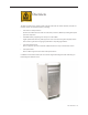
Overview The Mac Pro form factor is similar to that of earlier Power Mac G5 models. However, the Mac Pro includes several new hardware features, including: • Two dual-core Intel processors All Mac Pro models have two dual-core Intel Xeon processors, effectively making them quad processor computers.
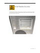
Serial Number Location To identify a particular Mac Pro computer, check the computer’s serial number. You can find the serial number within the model’s configuration label, which is located on the computer’s back panel directly below the video ports.
Service Source Take Apart Mac Pro © 2006 Apple Computer, Inc. All rights reserved.
General Information Orientation For most take-apart procedures, it is recommended that you lay the computer on its side before removing or installing the part. For proper operation, however, Apple recommends that the unit be run in the upright position. The computer should never be operated on its side with the access panel facing down.
Opening the Computer Tools No tools are required for this procedure. Preliminary Steps 1. Shut down the computer. Warning: Always shut down the computer before opening it to avoid damaging its internal components or the components you are installing. Do not open the computer or attempt to install items inside it while it is on. 2. Wait 5 to 10 minutes to allow the computer’s internal components to cool. Warning: After you shut down the system, the internal components can be very hot.
Procedure 1. Hold the side access panel and lift the latch on the back of the computer. Warning: The edges of the access panel and the enclosure can be sharp. Be very careful when handling them. 2. Remove the access panel and place it on a flat surface covered by a soft, clean cloth. Replacement Note: Make sure the latch is in the up position before replacing the access panel. If the latch is down, the access panel will not seat correctly in the enclosure.
Hard Drives The Mac Pro computer can accommodate four serial ATA (SATA) 3 Gbps hard drives in its four internal hard drive bays. In most configurations, a single hard drive occupies the far left bay (bay 1). The hard drives must meet the following specifications: • Type: SATA 3 Gbps • Width: 3.9 inches (102 mm) • Depth: 5.7 inches (147 mm) • Height: 1.0 inch Tools The only tool required for this procedure is a Phillips #1 screwdriver.
Part Location Procedure 1. Make sure the latch on the back panel is up, so that the drives and carriers are unlocked. 2. Pull the hard drive out of the drive bay.
3. If you are replacing the hard drive with a new drive, remove the four screws that mount the drive to the carrier and mount the new drive in the carrier. Important: Hold the drive by its sides. Be careful not to touch the printed circuit board on the bottom of the drive. Replacement Note: Slide the carrier and drive over the guides and into the drive bay, until you feel the drive snap into place. Note: If you install a new (replacement) drive, format it by following these steps: 1.
Optical Drive Carrier and Optical Drives The Mac Pro computer can accommodate two optical drives in the optical drive bay. If the computer has only one optical drive, it is installed in the top position. Note: To eject the drives, use the following: • Top drive: Press the Eject key. • Bottom drive: Press the Option and Eject keys. Tools The only tool required for this procedure is a Phillips #1 screwdriver.
Procedure Removing the Optical Drive Carrier and Optical Drives 1. Make sure the latch on the back panel is up, so that the drives and carriers are unlocked. 2. Pull the optical drive carrier part way out of the computer.
3. Disconnect the power and ribbon cables from the optical drive(s) and remove the carrier. 4. • • If you are replacing the optical drive with a new optical drive, do the following: Remove the four mounting screws and remove the optical drive from the carrier. Use the four screws to mount the replacement drive in the carrier. Note: If you are adding a second drive to the carrier, use the four screws stored on the back of the drive carrier to secure the drive to the carrier.
Replacing the Optical Drive Carrier and Optical Drives Important: Use the original Apple cables that came with the computer when you install or replace the optical drives. If just one optical drive is installed, tuck the cables for the second drive out of the way. 1. Attach the power and ribbon cables to the back of the drive(s). Important: Attach the connector on the end of the optical drive ribbon cable and the connector in the middle of the optical drive power cable to the top drive.
Memory (FB-DIMMs) and Memory Riser Cards The Mac Pro computer has two memory riser cards with a total of 8 memory slots. On each card, the slots are arranged as two banks of two slots each. The computer comes with a minimum of 1 GB of memory, installed as a pair of 512 MB fully buffered, dual inline memory modules (FBDIMMs) in two of the DIMM slots. Additional DIMMs can be installed in the open DIMM slots, as illustrated below. Note: DIMMs must be installed in pairs of equal size from the same vendor.
DIMMs for Mac Pro must fit these specifications: • 667 MHz, FB-DIMMs • 72-bit wide, 240-pin modules • 36 devices maximum per DIMM • Error-correcting code (ECC) Memory from older Macintosh computers is not compatible with Mac Pro. Important: For proper operation of Mac Pro computers, Apple recommends using only Appleapproved Mac Pro FB-DIMMs. Refer to GSX for Apple FB-DIMMs service part numbers. Tools No tools are required for this procedure.
Procedure 1. Holding the memory riser card by the two finger holes, pull it out of the memory cage and place the card DIMM side up on a soft, clean cloth. 2. Open the ejectors on the DIMM slot by pushing them out to the sides, and remove the DIMM from the riser card.
Replacement Note: Align the DIMM in the slot on the riser card and push both ends of the DIMM down until the ejectors snap back up into place. Warning: FB-DIMMs carry heatsinks on either side of the DIMM. Never attempt to remove the heatsinks from the DIMMs. Doing so could damage the DIMM.
PCI Express/Graphics Card The Mac Pro logic board includes one double-wide PCI Express graphics slot and three PCI Express expansion slots, for a total of four slots. The computer comes with a graphics card installed in slot 1. You can install additional PCI Express graphics and expansion cards in the remaining three PCI Express expansion slots. Important: Graphics cards from previous Power Mac G5 models are not compatible with Mac Pro models.
Preliminary Steps Before you begin, open the computer, and lay it on its side with the access side facing up. Note: You may also find it helpful to remove the hard drives and carriers and any adjacent PCI Express cards before beginning this procedure.
Procedure This procedure explains how to remove a standard card and a card that includes a booster cable. Before you can remove either type of card, however, you must first loosen the two captive screws that secure the PCI bracket to the enclosure and remove the bracket. Warning: When removing or installing a card, handle it only by the edges. Do not touch its connectors or any of the components on the card.
Standard Card 1. Release the small locking clip at the front of the card’s logic board connector by pushing the clip up toward the media shelf. 2. Holding the card by the top corners, pull up the card and remove it from its expansion slot. Replacement Note: Align the card’s connector with the expansion slot and press until the connector is inserted all the way into the slot. If you’re installing a 12-inch card, make sure the card engages the appropriate slot in the PCI card guide.
Card with Booster Cable 1. Disconnect the booster cable from the logic board. 2. Release the small locking clip at the front of the card’s logic board connector by pushing the clip up toward the media shelf. 3. Holding the card by the top corners, gently pull up the card and remove it from its expansion slot. 4. If you are replacing the booster cable with a new booster cable, disconnect the cable from the card.
Replacement Note: There are two logic board connectors for booster cables. Connect the booster cable for a card in PCI slot 1 to the lower connector. Connect the booster cable for a card in PCI slot 2 to the upper connector.
Power Supply Tools The only tool required for this procedure is a magnetized 2.5 mm hex wrench. You may also find a flat-blade screwdriver helpful in releasing some cable connectors.
Procedure Removing the Power Supply 1. Using a magnetized 2.5 mm hex wrench remove the four power supply mounting screws from the bottom of the media shelf. 2. Depress the upper right corner of the power supply and slide the power supply toward the front of the computer.
Note: Before beginning the next step, place a soft cloth over the edge of the enclosure to prevent scratches from the power supply. 3. Lift the power supply a short distance and rest it on the edge of the enclosure. Note: The power supply is still connected to the enclosure by its cable.
4. Starting with the top connector and working down, disconnect the four connectors on the power supply cable from the four connectors on the power harness cable. Note: You must release the locking latch on each power supply cable connector before detaching the connector. 5. Remove the power supply from the enclosure.
Replacing the Power Supply Note: To protect against scratches, make sure a soft cloth covers the edge of the enclosure next to the power supply bay. 1. Rest the power supply on the edge of the enclosure so that its cable can reach the media shelf divider. Note: The following four steps explain how to reconnect the power supply cable connectors with the power harness connectors.
2. Starting with the top connector and working down, release the four power harness cable connectors from their openings in the media shelf divider. Note: Each connector has two locking latches that hold it to the divider. To release the connector, depress the bottom latch first and then the top latch. You may find a flat-blade screwdriver useful in depressing the latches. 3.
Repeat for the other three power supply cable connectors. 4. Important: The first three connectors on the power supply cable are marked J1, J2, and J3; the fourth connector is not marked. The four connectors on the power harness cable are marked PS1, PS2, PS3, and PS4. You must connect J1 to PS1, J2 to PS2, etc. 5. Starting at the bottom connector and working up, depress the locking latches on each power harness connector and reinsert it into its opening in the media shelf divider.
Important: Test that all power supply cable connectors and power harness connectors are fully seated by tugging on the cables on both sides of each of the four paired connectors. 6. Fold the power supply cable on the bottom of the power supply bay. 7. Lift the power supply and remove the soft cloth from the edge of the enclosure. 8. Holding the power supply at an angle, as illustrated, lower it into the enclosure until its upper right corner slides under the corner lip of the enclosure.
9. Slide the power supply toward the back of the computer as far as possible. 10. Make sure the power receptacle aligns with the opening in the enclosure’s back panel and the four screw holes in the power supply align with the screw holes in the media shelf. 11. Replace the four power supply mounting screws.
Power Supply Fan Tools The only tools required for this procedure are a magnetized 2.5 mm hex wrench and needlenose pliers. You may also find scissors or wire cutters helpful.
Procedure Note: To remove the power supply fan, you must first move the power supply out of the way; you do not, however, have to remove the power supply entirely from the enclosure. 1. Using a magnetized 2.5 mm hex wrench, remove the four power supply mounting screws from the bottom of the media shelf. 2. Depress the upper right corner of the power supply and slide the power supply toward the front of the computer.
Note: Before beginning the next step, place a soft cloth over the edge of the enclosure to prevent scratches from the power supply. 3. Lift the power supply a short distance and rest it on the edge of the enclosure. Note: The power supply is still connected to the enclosure by its cable. When moving the power supply to the edge of the enclosure, be careful not to put too much tension on the cable.
4. Disconnect the power supply fan cable from the logic board and thread the cable through the opening in the media shelf. 5. Using needlenose pliers, pull out the four grommets that mount the power supply fan to the media shelf divider. Note: You may find scissors or wire cutters useful in snipping off the grommet heads.
6. Rotate the fan and remove it from the enclosure.
Replacing the Power Supply Fan 1. Place the power supply fan in the media shelf and thread the fan’s cable through the opening in the shelf. 2. Connect the cable to the logic board. 3. Rotate the fan into place flush against the media shelf divider. Make sure the back of the fan faces the divider, as illustrated.
Note: To secure the power supply fan to the divider, use the long-tailed grommets enclosed with the replacement fan. 4. Thread the first grommet, tail first, through one of the four grommet holes in the divider and on through the corresponding grommet hole in the fan bracket. Then pull to secure the grommet and detach the excess threading tail. (The tail is notched to break off at the correct place.) 5. Repeat for the other three grommets.
6. Fold the power supply cable on the bottom of the power supply bay. 7. Holding the power supply at an angle, as illustrated, lower it into the enclosure until its upper right corner slides under the corner lip of the enclosure. 8. Slide the power supply toward the back of the computer as far as possible.
9. Make sure the power receptacle aligns with the opening in the enclosure’s back panel and the four screw holes in the power supply align with the screw holes in the media shelf. 10. Replace the four power supply mounting screws.
AirPort Extreme Card Important: The computer enclosure includes AirPort antenna wires and a Bluetooth antenna wire. The Bluetooth antenna wire looks similar to the AirPort antenna wires, except that it includes a “BT” label. For proper operation, be careful not to connect the Bluetooth antenna wire to the AirPort card or any AirPort antenna wire to the Bluetooth card. Note: You may connect the AirPort antenna wires to either AirPort card connector.
Procedure 1. Remove the two AirPort Extreme card mounting screws. 2. Lift the AirPort Extreme card a short distance from the logic board. 3. Disconnect the AirPort antenna wires from the card.
4. Remove the card from the enclosure. Replacement Note: To replace the AirPort Extreme card, do the following: • Connect the antenna wires to the card. Important: Be sure to connect the wires that are marked 1 and 3 to the card; the antenna wire that is marked 2 should be taped out of the way. • Insert the card into its logic board connector at an angle, as illustrated. • Lower the screw end of the card down to the standoffs on the logic board and replace the two mounting screws.
Bluetooth Card Important: The computer enclosure includes one Bluetooth antenna wire, which looks similar to the AirPort antenna wires, except that it includes a “BT” label. For proper operation, be careful not to connect the Bluetooth antenna wire to the AirPort card or any AirPort antenna wire to the Bluetooth card. Tools The only tool required for this procedure is a magnetized jewelers Phillips #1 screwdriver.
Procedure 1. Remove the two Bluetooth card mounting screws. 2. Lift the Bluetooth card a short distance from the logic board. 3. Disconnect the Bluetooth antenna wire from the card. 4. Remove the card from the enclosure. Note: If you are not replacing the Bluetooth card, cover the connector on the Bluetooth antenna wire with Kapton or other non-conductive tape to prevent it from shorting out components on the logic board.
Battery Tools No tools are required for this procedure. You may, however, find a flat-blade screwdriver useful in removing the battery from its holder. Preliminary Steps Before you begin, open the computer, lay it on its side with the access side facing up, and remove any PCI Express cards that block access to the battery.
Procedure 1. Slide the battery out from underneath the battery holder’s metal clip. 2. Remove the battery from its holder. Replacement Note: Insert the new battery into the holder, making sure the battery’s positive symbol (+) faces up. Warning: Installing the battery incorrectly may cause an explosion. Be sure the battery’s positive and negative sides are correctly oriented in the holder. Use only the same type of battery or an equivalent recommended by the manufacturer of the original.
Processor Heatsink Cover Tools The only tools required for this procedure are the following: • Long-handled, magnetized #1 Phillips screwdriver • Short-handled, magnetized jeweler’s #1 Phillips screwdriver or right-angle, magnetized #1 Phillips screwdriver • Apple Mac Pro wrench (part number 922-8025) • Flat-blade screwdriver Preliminary Steps Before you begin, open the computer, lay it on its side with the access side facing up, and remove the following: • PCI Express card installed in slot 1 • Top and bo
Procedure Note: To remove the heatsink cover, you must first slide the memory cage toward the back panel. 1. Using a long-handled, magnetized #1 Phillips screwdriver, remove the two long screws that mount the memory cage to the logic board. 2. Using a short-handled, magnetized jeweler’s #1 Phillips screwdriver or right-angle, magnetized #1 Phillips screwdriver, carefully remove the two short screws that mount the memory cage to the bottom panel of the enclosure.
If either of the two short mounting screws for the memory cage strip while you are attempting to remove it, the screw will stay attached to its hex standoff located below the cage and you will be unable to remove the screw. In this case, do the following. Note: To avoid scratching the enclosure in the following step, place a piece of sticky note paper or removable masking tape over the enclosure edge where you insert the wrench.
3. Slide the memory cage toward the rear panel of the computer. Lift the heatsink cover slightly, rotate it as illustrated, and remove the cover from the enclosure.
Replacement Note: When reinstalling the processor heatsink cover, do the following: • Make sure the heatsink cover slides below slot #1 on the PCI card guide, which is attached to the front fan assembly. • Align the four slots on the underside of the heastink cover’s left edge with the four tabs on the front fan before snapping the heatsink cover into place.
Front Fan Assembly Tools The only tools required for this procedure are a long-handled, magnetized #1 Phillips screwdriver and the cover from a PCI Express card slot.
Procedure 1. Using a long-handled, magnetized #1 Phillips screwdriver, remove the front fan assembly mounting screw. 2. Insert the right-angle end of a cover for one of the PCI Express card slots between the enclosure and the lower left edge of the front fan, and using force, lift straight up. Then gripping the front fan by the upper right edge and the lower left edge, lift straight up and remove the fan from the enclosure.
Replacement Note: When lowering the front fan into the enclosure, slide the guide on the base of the fan assembly into the channel on the speaker assembly. Also make sure the latch on the inside top left edge of the fan assembly engages with the slot on the inside lip of the enclosure. Then press down until you hear the fan click into place in the connector on the logic board Replacement Note: Be careful not to crimp any AirPort or Bluetooth antenna wires under the fan assembly.
Mac Pro RAID Card & Battery Note: If a Mac Pro RAID Card is installed in a Mac Pro, the standard iPass cable routing has been changed so that the cable connects to the card, rather than to the logic board. Tools The only tool required for this procedure is a Phillips #1 screwdriver. You might also find a small flat-blade screwdriver helpful in releasaing the iPass cable connector.
Procedure 1. If you have not already done so, loosen the two captive screws that secure the PCI bracket to the enclosure and remove the bracket. Warning: When removing or installing a card, handle it only by the edges. Do not touch its connectors or any of the components on the card. Lift the card straight out from the connector to remove it, and insert it straight into the connector to install it. Do not rock the card from side to side and don’t force the card into the slot.
2. Release the small locking clip at the front of the card’s logic board connector by pushing the clip up toward the media shelf. 3. Holding the card by the top corners, gently pull up the card and remove it from its expansion slot. Note: The Mac Pro RAID Card must always be installed in slot 4.
4. Disconnect iPass cable from the Mac Pro RAID Card. Note: You may find it helpful to use a small, flat-blade screwdriver to release the cable connector. Depress the rear edge of the silver-colored latch on top of the connector. 5. Remove the card from the enclosure.
6. The Mac Pro RAID Card includes its own battery. If you are replacing the battery on the card, do the following: • Disconnect the battery cable from the card. • Remove the four mounting screws and lift the battery from the card. Important: Do not drop, disassemble, crush, incinerate, or expose the battery to temperatures above 212° F (100° C). Stop using the battery if it appears damaged in any way. Replace the battery only with an Apple-authorized battery for this product.
Replacing the Mac Pro RAID Card 1. Connect the iPass cable to the Mac Pro RAID Card. 2. Align the card’s connector with expansion slot 4 and press until the connector is inserted all the way into the slot. Make sure the card also engages slot 4 in the PCI card guide. Note: • Don’t rock the card from side to side; instead, press the card straight into the slot. • Don’t force the card. If you meet a lot of resistance, pull the card out.
Processor Heatsinks Note: The processor heatsink requires thermal grease for proper operation. Every time you remove the processor heatsink, you must replace the thermal grease. New grease and alcohol wipes for cleaning off the previous grease are included with replacement processors and logic boards. Instructions for applying the grease are included with this procedure. Note that replacement processor heatsinks come with the grease already applied.
Part Location Procedure 1. Disconnect the 2-pin cable for the upper processor (CPU A) heatsink from the logic board.
2. Using a long-handled, magnetized 3 mm flathead hex screwdriver, loosen the four captive mounting screws for the upper processor heatsink in the order indicated below. 3. Lift the heatsink straight up and out of the enclosure. 4. Move the memory cage out of the way so that you can locate the cable connector for the lower processor heatsink. 5. Disconnect the cable. 6. Repeat steps 2 and 3 for the lower processor (CPU B) heatsink.
Replacement Note: Before reinstalling an existing processor heatsink, follow these directions for applying new thermal grease to the underside of the heatsink. • Using the alcohol pad included with the logic board or processor replacement part, clean off any used thermal grease from the processor and the bottom of the heatsink. • Using the thermal grease included with the logic board or processor replacement part, apply one dot of fresh grease to the raised square area on the bottom of the heatsink.
Note: If you are replacing a processor heatsink with a new heatsink, do not reapply thermal grease. The new heatsink comes with thermal grease already in place, covered by a cap over the bottom of the heatsink. Before installing the heatsink, remove the cap. Replacement Note: If you are replacing either the upper or lower processor heatsink with a new heatsink, apply the enclosed gasket to the top of the heatsink, as illustrated below.
Memory Cage with Rear Fan The rear fan is part of the memory cage assembly. If you need to replace the rear fan, you must replace the entire memory cage assembly. Note: Every time you remove the memory cage, you must replace the thermal grease on the processor heatsinks. New grease and alcohol wipes for removing the previous grease are available as a separate kit (part number 076-1225). Instructions for applying the grease are included with the processor heatsinks procedure.
Part Location Procedure 1. Disconnect the rear fan cable from the logic board. 2. Lift the memory cage out of the enclosure. Replacement Note: When installing the memory cage, make sure all cables are out of the way so that the cage sits properly and the cable harness below it is not pinched or damaged when you tighten the screws.
Replacement Note for Cages with Stripped Screws: If either of the two short mounting screws for the memory cage stripped while you were attempting to take out the heatsink cover (see step 2 in “Processor Heatsink Cover,” the screw and hex standoff will stay attached to the memory cage when you remove it. In this case, before replacing the memory cage in the enclosure, do the following. • Using pliers and a socket wrench, separate the hex standoff from the mounting screw.
Processors This procedure illustrates how to remove the lower processor (CPU B). The instructions are the same for removing the upper processor (CPU A). You may, however, want to use a flat-blade screwdriver to release the latch on the upper processor. Note: Every time you remove a processor, you must replace the thermal grease on the processor heatsink. New grease and alcohol wipes for removing the previous grease are included with replacement processors.
Preliminary Steps Before you begin, open the computer, lay it on its side with the access side facing up, and remove the following: • Hard drives and hard drive carriers in drive bays 1 and 2 • PCI Express card installed in slot 1 • Any 12-inch PCI Express cards • Top and bottom memory cards • Processor heatsink cover • Front fan assembly • Processor heatsinks • Memory cage Part Location Mac Pro Take Apart — Processors 77
Procedure 1. Release the latch on the metal processor holder. Note: You may want to use a flat-blade screwdriver to release the latch on the upper processor. 2. Rotate the top of the holder to the open position.
3. Lift the processor out of the holder. Important: When removing or installing a processor, always hold the processor by the edges. Be extremely careful not to touch the gold pins on the bottom of the processor, as this type of connector is very sensitive to contamination. Also be careful not to touch the gold pins in the processor socket on the logic board.
Note: You can identify the processor by the speed etched on the processor can, as illustrated below. You must clean off the thermal grease from installed processors to see the speed. Replacement Note: Before installing a replacement processor, remove the protective cap covering the new processor’s connector.
Replacement Note: When installing the processor on the logic board, align the processor notch with the tab on the processor holder, as illustrated. Then lower the processor straight down onto the socket. Replacement Note: Make sure the two logic board bumpers by the upper processor are in place before you reinstall the heatsinks. Note: Unlike in earlier Power Mac G5 computers, replacing a processor in Mac Pro does not require running Apple Service Diagnostic for thermal calibration..
Important: For the new processor to perform properly, the logic board must be upgraded to the latest version of the BootROM. You can download the latest version from the Apple support web site: http://www.apple.com/support/downloads/ Specifically, see KnowledgeBase article 303880, “Firmware Updates for Intel-based Macs.
Speaker Assembly Tools The only tools required for this procedure are a magnetized #1 Phillips screwdriver and a magnetized jeweler’s #0 Phillips screwdriver.
Part Location Mac Pro Take Apart — Speaker Assembly 84
Procedure 1. Remove the three speaker assembly mounting screws. 2. Carefully pivot the speaker assembly a short distance away from the enclosure. 3. Disconnect the speaker assembly cable from the logic board. 4. Remove the speaker assembly from the computer.
5. If you are replacing the speaker in the assembly bracket, do the following: • Slide the speaker cable through the opening in the speaker bracket. • Using a magnetized jeweler’s #0 Phillips screwdriver, remove the four mounting screws. 6. Remove the speaker and cable from the bracket.
USB Cable Tools No tools are required for this procedure.
Part Location Mac Pro Take Apart — USB Cable 88
Procedure 1. Disconnect the USB cable from connector J201 on the front panel board. 2. Disconnect the USB cable from connector J2D1 on the logic board. 3. Remove the cable from the enclosure.
Logic Board Note: Every time you remove the logic board, you must replace the thermal grease on the processor heatsinks. New grease and alcohol wipes for removing the previous grease are included with replacement logic boards. Instructions for applying the grease are included with the processor heatsinks procedure. Tools The only tool required for this procedure is a magnetized Phillips #1 screwdriver.
Part Location Mac Pro Take Apart — Logic Board 91
Procedure 1. To keep them out of the way, temporarily tape the antenna cables to the bottom of the media shelf. Important: Be sure to disconnect all cables from the logic board before you remove the logic board mounting screws.
2. Starting at the back panel side of the logic board and working clockwise around the board, disconnect all cables from the logic board. Note: There are 14 cables you will be disconnecting from the logic board.
3. Using a magnetized #1 Phillips screwdriver, remove the eight black logic board mounting screws.
4. Slide the logic board back a short distance from the port openings in the back panel. Make sure the ports clear the openings. 5. Tilt the top edge of the logic board up and maneuver the board out of the enclosure.
Replacement Note: Before replacing the logic board, check the underside of the board to be sure that all bumpers are in place. Replace any missing bumpers. Replacement Note: Also check that the two bumpers are in place by the upper processor on the top side of the logic board. Replace any missing bumpers.
Replacement Note: If you are replacing the logic board with a new logic board, do the following: • Remove the protective caps from the new logic board’s processor holders and transfer the caps to the original logic board’s processor holders. Note that logic boards returned to Apple without the protective caps may be rejected. Warning: Be careful not to touch the gold pins in the processor socket on the logic board.
• Transfer the following to the new board: • Processors • DIMMs • PCI Express/graphics cards • AirPort Extreme card (if installed) • Bluetooth card (if installed) • You must also transfer the back ports EMI shield to the new board. Replacement Note: To replace the logic board, tilt the board as illustrated and lower it into the enclosure. Note: Unlike in earlier Power Mac G5 computers, replacing a logic board in Mac Pro does not require running Apple Service Diagnostic for thermal calibration.
Important: For proper performance, all logic boards in Intel-based desktop computers and servers must be upgraded to the latest version of the BootROM. You can download the latest version from the Apple support web site: http://www.apple.
Front Panel Board Tools The only tool required for this procedure is a long-handled, magnetized Phillips #1 screwdriver.
Part Location Mac Pro Take Apart — Front Panel Board 101
Procedure 1. Disconnect the optical drive ribbon cable from the logic board and move the cable out of the way.
2.
3. Using a magnetized #1 Phillips screwdriver, remove the five front panel board mounting screws. 4. Lift the front panel board out of the computer. Note: If you are replacing the front panel board with a new front panel board, separate the EMI shield from the back of the board and transfer it to the new front panel board.
Power Button Tools The only tool required for this procedure is a jeweler’s flat-blade screwdriver.
Part Location Mac Pro Take Apart — Power Button 106
Procedure 1. Disconnect the optical drive ribbon cable from the logic board and move the cable out of the way. 2. Disconnect the front panel board power cable from the front panel board and move it out of the way. 3. Disconnect the power button cable from the front panel board. 4. Lay the computer so that the front panel is facing down.
5. Remove the black rubber cap that covers the power button LED. 6. Using a jeweler’s flat-blade screwdriver, pry up the metal C-ring that secures the power button board. 7. Lift up and remove the power button board.
8. Remove the metal activation ring that lies below the power button board. 9. Remove the power button from the enclosure.
AirPort Antenna Board with Cables The AirPort Extreme antenna cables are part of the AirPort antenna board assembly. To remove or replace the cables, you must replace the antenna board assembly Tools The only tools required for this procedure are a jeweler’s flat-blade screwdriver and a magnetized jeweler’s Phillips #0 screwdriver.
Part Location Procedure 1. Place the computer so that the bottom panel is facing you. 2. Using a jeweler’s flat-blade screwdriver, pry open the two latches on the antenna wire ferrite bead and remove the bead from the wires.
3. Using the jeweler’s flat-blade screwdriver, carefully pry up the rectangular plastic plate on the bottom panel. 4. Using a jeweler’s #0 Phillips screwdriver, remove the four antenna board mounting screws.
5. Tilt the antenna board away from the back panel a short distance. 6. Feed each antenna wire separately out through the small opening in the bottom panel. 7. Remove the antenna board and cables from the enclosure.
Optical Drive Power Cable Tools The only tool required for this procedure is a magnetized #1 Phillips screwdriver.
Procedure 1. Using a magnetized #1 Phillips screwdriver, remove the two mounting screws on the hard drive connector for drive bay 1 and move the connector out of the way. 2. Unwind the tape that holds the optical drive data cable to the optical drive power cable. 3. Disconnect the optical drive power cable from the logic board. 4. Insert the logic board end of the power cable into the opening in the media shelf at hard drive bay 1 and remove the cable from the enclosure.
Mac Pro Take Apart — Optical Drive Power Cable 116
Optical Drive Data (Ribbon) Cable Tools The only tool required for this procedure is a magnetized #1 Phillips screwdriver.
Part Location Procedure 1. Using a magnetized #1 Phillips screwdriver, remove the two mounting screws on the hard drive connector for drive bay 1 and move the connector out of the way.
2. Unwind the tape that holds the optical drive data cable to the optical drive power cable. 3. Disconnect the optical drive data cable from the logic board. 4. Insert the cable into the opening in the media shelf at hard drive bay 1 and remove the cable from the enclosure.
Ambient Board Note: The ambient board is attached to the enclosure with adhesive. Once you remove the ambient board, you may have to apply new adhesive before reattaching the same ambient board. Replacement ambient boards come with adhesive already in place. Tools The only tools required for this procedure are a jeweler’s flat-blade screwdriver. Preliminary Steps Before you begin, open the computer, lay it on its side with the access side facing up, and remove the optical drive carrier and optical drives.
Procedure 1. Locate the ambient board on the inside left corner of the top panel, above the optical drive carrier. 2. Disconnect the ambient board cable from the ambient board. 3. Using a jeweler’s flat-blade screwdriver, carefully pry the board from the enclosure. Important: After you replace the ambient board, you must reset the System Management Controller. Refer to “Resetting the Logic Board” in the Troubleshooting chapter.
Ambient Board Cable Tools The only tool required for this procedure is a magnetized #1 Phillips screwdriver.
Procedure 1. Remove any tape holding the ambient board cable to the enclosure. 2. Disconnect the ambient board cable from the ambient board and logic board. 3. Using a magnetized #1 Phillips screwdriver, remove the two mounting screws on the hard drive connector for drive bay 1 and move the connector out of the way. 4. Route the ambient board cable out through the opening in the media shelf and remove the cable from the enclosure.
Bluetooth Antenna Board and Cable The Bluetooth antenna cable is part of the Bluetooth antenna board assembly. To remove or replace the cable, you must replace the antenna board assembly. Tools The only tool required for this procedure is a jeweler’s flat-blade screwdriver.
Part Location Procedure 1. Insert a jeweler’s flat-blade screwdriver into the notch on either side of the Bluetooth antenna cage and carefully pry up the cage from the enclosure.
2. Remove the Bluetooth antenna from its routing under the PCI port cage. 3. Remove the Bluetooth antenna from its guide on the far side of the PCI port cage. 4. Remove the antenna board and antenna from the enclosure.
Hard Drive Cable Harness The hard drive cable harness consists of the hard drive data cable and the hard drive power cable taped together. The cables are not available as separate service parts. Tools The only tools required for this procedure are a long-handled, magnetized #1 Phillips screwdriver.
Part Location Procedure 1. Disconnect the hard drive data and power cable connectors from the logic board.
2. Using a long-handled, magnetized #1 Phillips screwdriver, remove the two screws holding the hard drive cable harness connector to the bracket below hard drive bay 1. 3. Remove the connector from the bracket. 4. Repeat for the other three connectors below hard drive bays 2, 3, and 4. 5. Remove the hard drive cable harness from the enclosure.
Hard Drive Temperature Sensor Cable The hard drive temperature sensor cable is a wire harness with four connectors, one for each hard drive temperature sensor. Be careful not to catch or damage any of the wires when removing the harness from the enclosure. Tools No tools are required for this procedure.
Part Location Mac Pro Take Apart — Hard Drive Temperature Sensor Cable 131
Procedure 1. Disconnect the hard drive temperature sensor cable from the logic board. 2. Disconnect the four connectors on the hard drive temperature sensor cable from the four hard drive temperature sensors. 3. Remove the hard drive temperature sensor cable from the enclosure. Replacement Note: The connectors on the hard drive temperature sensor cable are labeled with HDD1, HDD2, HDD3, and HDD4 to indicate the connector that belongs to each temperature sensor.
Hard Drive Temperature Sensor There are four hard drive temperature sensors, one for each hard drive. This procedure explains how to remove the sensor for the hard drive in drive bay 1. The procedure for removing the other three sensors is similar, except that the only part you need to remove before beginning the procedure is the hard drive directly over the sensor. Tools The only tools required for this procedure are a mirror and a black stick or a flat-blade screwdriver.
Part Location Procedure 1. Disconnect the sensor cable for the hard drive in bay 1 and move the cable out of the way.
2. Using a mirror, locate the two round black nubs on the bottom of the hard drive sensor below hard drive bay 1. 3. Using a black stick or a flat-blade screwdriver, press up on the nubs and remove the sensor from the enclosure.
Power Cable Harness The power cable harness consists of the following cables: • Power supply PS1 cable • Power supply PS2 cable • Power supply PS3 cable • Power supply PS4 control cable • Front panel board power cable • Front panel board audio cable • Front panel board FireWire 800 cable Tools No tools are required for this procedure.
Part Location Procedure 1. Disconnect the power cable harness connectors from the logic board.
2. Slip the four connectors out through the opening in the media shelf, removing them one at a time. 3. Remove the power harness cable from its routing along the edge of the logic board, over the speaker assembly, and along the bottom lip of the enclosure. 4. Remove the power harness cable from the enclosure.
Service Source Troubleshooting Mac Pro © 2006 Apple Computer, Inc. All rights reserved.
General Information Memory The Mac Pro computer has two memory cards with a total of 8 memory slots. On each card, the slots are arranged as two banks of two slots each. The computer comes with a minimum of 1 GB of memory, installed as a pair of 512 MB fully buffered, dual inline memory modules (FB-DIMMs) in two of the DIMM slots. Additional DIMMs can be installed in the open DIMM slots, as illustrated below. Note: DIMMs must be installed in pairs of equal size from the same vendor.
DIMMs for Mac Pro must fit these specifications: • 667 MHz, FB-DIMMs • 72-bit wide, 240-pin modules • 36 devices maximum per DIMM • Error-correcting code (ECC) Important: For proper operation of Mac Pro computers, Apple recommends using only Appleapproved Mac Pro FB-DIMMs. Refer to GSX for Apple FB-DIMMs service part numbers. PCI Express Cards The Mac Pro logic board includes one double-wide PCI Express graphics slot and three PCI Express expansion slots, for a total of four slots.
Mac Pro Troubleshooting — General Information 142 922-7684 922-7686 922-7687 922-7688 Optical Drive Power Optical Drive IDE Power Supply PS#1 Power Supply PS#2 865 695 150 922-7685 922-7690 922-7692 922-7731 Front Panel Board Power Front Panel Board Audio Front Panel Board FireWire-800 922-7691 922-7693 Power Supply Control PS#4 Front Panel Board USB Intake Ambient Temperature Sensor 400 860 1160 922-7689 Power Supply PS#3 370 605 1170 586 559 610 922-7730 HDD Thermal Senso
Cable Connector Locations Use the diagram below to find the location of the internal cable connectors on the logic board. A B C D E F G H J K 9 9 8 8 7 7 6 6 5 5 4 4 3 3 2 2 1 1 A B C D E F G H J K Thermal Calibration Unlike in earlier Power Mac G5 computers, replacing a processor in a Mac Pro computer does not require running Apple Service Diagnostic for thermal calibration.
Block Diagram The architecture of the Mac Pro is based on two dual-core Intel Xeon processors, the North Bridge memory controller and the South Bridge I/O controller, as shown in the simplified block diagram below.
Resetting the Logic Board System Management Controller (SMC) Reset The System Management Controller (SMC) is a chip on the logic board that controls all power functions for the computer. If the computer is experiencing any power issue, resetting the SMC may resolve it.
Real Time Clock (RTC) Reset The Real Time Clock (RTC) is a chip on the logic board that controls the date and time functions of the computer. If the computer is experiencing an issue booting, resetting the RTC may resolve it. Follow these steps to reset the RTC: 1. From the Apple menu, choose Shut Down (or if the computer is not responding, hold the power button until it turns off). 2. Unplug the AC power cord. 3. Remove the battery for at least 20 seconds.
Diagnostic LEDs The Mac Pro logic board includes a set of LEDs to help service providers troubleshoot the computer. The LEDs are located toward the rear of the logic board, under the memory cage, next to PCI card slot 1. You can view these LEDs by removing the computer’s side access panel and looking through the memory cage to the logic board below. LEDs 2, 3, 4, and 5 are normally off and will automatically illuminate if an error occurs.
Use the following table to interpret the LEDs.
LED 2 CPU B (Lower Processor) Error LED 3 CPU A (Upper Processor) Error Normally off. These LEDs come on if an error occurs or if the BootROM is corrupted. They do not depend on the DIAG_LED button being pressed. Related symptoms include no video or the computer is hung up. If the BootROM is corrupted, the optical drive tray should eject, prompting for the insertion of a recovery disc to restore the BootROM. Troubleshooting: • With the computer booted, up press the SYS_RST switch.
• Replace the processor associated with the corresponding LED. LED 6 GPU Present Normally on when DIAG_LED button is pressed. If this LED is on, it indicates there is a graphics card installed and recognized by the computer. It does not indicate that the graphics card is fully functional. Some graphics cards require additional power to function, which is available from connectors on the logic board.
Memory Riser Card Diagnostic LEDs Both of the memory riser cards include diagnostic LEDs for each DIMM. Each of the LEDs will light if it detects an issue with the corresponding installed DIMM. These LEDs will also flash briefly when the computer is started up or shut down and when it goes in and out of sleep mode. This is normal behavior. Troubleshooting: • Shutdown and restart the computer. • Try reseating the DIMMs. • Check memory installation instructions for proper installation order.
Power Supply Verification To power on, the computer’s logic board requires “trickle” power. If the system fails to power on, first reset the SMC as described in this chapter. If the computer still doesn’t power on, follow the procedure outlined below to determine whether the issue is related to the power supply. Verify trickle power Diagnostic LED 1 indicates the presence of trickle power required by the logic board to begin the startup process.
• • • Blue system failure screens in Windows XP/Vista Not waking or sleeping when expected Bad media taking too long to eject (including holding mouse button down at startup taking minutes to eject) Symptoms that may be resolved by updating SMC firmware: • Fan related behavior (excessive speed or noise) • Loud audible clicking from some fans • Thermal shut down or warnings • Diagnostics reporting failures • Sleep/wake issues • Intermittent shut down • SMC causes bad/missing ambient sensor to cause the com
Symptom Charts How to Use the Symptom Charts The Symptom Charts included in this chapter will help you diagnose specific symptoms related to the product. Because cures are listed on the charts in the order of most likely solution, try the cures in the order presented. Verify whether or not the product continues to exhibit the symptom. If the symptom persists, try the next cure. Note: If a cure instructs you to replace a module, reinstall the original module before you proceed to the next cure.
8. Verify that processors’ mounting clamps are properly tightened. 9. Test whether the front panel board or power button is at fault. Remove the installed front panel board and test with a known-good front panel board. 10. Replace front panel board. 11. Replace power button. 12. Replace power supply. 13. Replace logic board. Power-on LED illuminates when pressed in, but goes out when button is released, there is no boot tone or video, but you can hear a small click 1.
3. Reset logic board. Refer to “Resetting the Logic Board” in this chapter. 4. Verify power supply cables are properly seated. 5. Check diagnostic LED 2 and/or LED 3 for processor connection 6. If only one of the CPU Error LEDs (LED 2 or 3) comes on, try swapping the processors. If the Error LED follows the processor to the other processor location, replace that processor. 7.
4. Replace the processors 5. Replace the logic board 6. Replace the power supply Fans Individual fan failure 1. Verify fan is properly connected. 2. Verify all other fans are working properly. If all fans seem to have failed, the problem is most likely not the fans. Reset the logic board to see if this resolves this problem. 3. Replace fan 4. Replace logic board Fans run at high speed (computer may shut down or may just hang and not shut down as a result) 1.
4. Remove the computer’s side access panel and observe the diagnostic LEDs, specifically LED 4 and LED 5 (the CPU A and B Overtemp LEDs). Refer to “Diagnostic LEDs” in this chapter for more information on how to locate and interpret these LEDs. If either of these LEDs is flashing, this may indicate an initial processor over temperature condition. If either of these LEDs is solidly on, this may indicate a chronic processor over temperature condition.
Front Panel USB 2.0 port 1. Reseat front panel board cables 2. Replace front panel board cables 3. Reseat front panel board 4. Replace front panel board 5. Replace logic board Rear Panel USB 2.0 port Replace logic board Internal speaker 1. Check speaker cable connection 2. Replace speaker 3. Replace logic board AirPort Extreme Card 1.
2. Reseat front panel board 3. Replace front panel board 4. Replace logic board Audio IO (rear audio line in; rear audio line out) 1. Start up the computer from a known-good volume (such as its Installation disc or an external hard drive), to isolate the issue to software or hardware. If the computer seems to perform adequately when booted in this way, troubleshoot as a software issue. If the computer continues to exhibit the issue, follow the steps below. 2.
Service Source Upgrades Mac Pro © 2006 Apple Computer, Inc. All rights reserved.
AirPort Extreme Card Important: The computer enclosure includes AirPort antenna wires and a Bluetooth antenna wire. The Bluetooth antenna wire looks similar to the AirPort antenna wires, except that it includes a “BT” label. For proper operation, be careful not to connect the Bluetooth antenna wire to the AirPort card or any AirPort antenna wire to the Bluetooth card. Note: You may connect the AirPort antenna wires to either AirPort card connector.
Procedure 1. Connect the AirPort antenna wires to the connectors on the card. Important: Be sure to connect the wires that are marked 1 and 3 to the card; the antenna wire that is marked 2 should be taped out of the way. 2. Insert the AirPort Extreme card into its logic board connector at an angle, as illustrated. Then lower the screw end of the card down to the standoffs on the logic board.
3. Install the two AirPort Extreme card mounting screws.
Bluetooth Card Important: The computer enclosure includes one Bluetooth antenna wire, which looks similar to the AirPort antenna wires, except that it includes a “BT” label. For proper operation, be careful not to connect the Bluetooth antenna wire to the AirPort card or any AirPort antenna wire to the Bluetooth card. Tools The only tool required for this procedure is a magnetized jewelers Phillips #1 screwdriver.
Procedure 1. Connect the Bluetooth antenna wire to the connector on the Bluetooth card. 2. Lower the card onto the Bluetooth connector on the logic board. 3. Install the two Bluetooth card mounting screws.
PCI Express/Graphics Card The Mac Pro logic board includes one double-wide PCI Express graphics slot and three PCI Express expansion slots, for a total of four slots. The computer comes with a graphics card installed in slot 1. You can install additional PCI Express graphics and expansion cards in the remaining three PCI Express expansion slots. Important: Combined maximum power consumption for all four PCI Express slots must not exceed 300 W.
Part Location Procedure This procedure explains how to install a standard card and a card that includes a booster cable. Before you can install either type of card, however, you must first loosen the two captive screws that secure the PCI bracket to the enclosure and remove the bracket. You must also remove the port cover for the PCI slot where you are installing the new card.
Warning: When installing or removing a card, handle it only by the edges. Do not touch its connectors or any of the components on the card. Standard Card 1. Align the card’s connector with the expansion slot and press until the connector is inserted all the way into the slot. If you’re installing a 12-inch card, make sure the card engages the appropriate slot in the PCI card guide. • Don’t rock the card from side to side; instead, press the card straight down into the slot. • Don’t force the card.
Card with Booster Cable 1. Connect the booster cable to the card. 2. Holding the card by the top corners, insert it straight down into its expansion slot. 3. Connect the booster cable to the logic board. Note: There are two logic board connectors for booster cables. Connect the booster cable for a card in PCI slot 1 to the connector that is closest to the heatsink cover. Connect the booster cable for a card in PCI slot 2 to the connector closest to the media shelf.
Service Source Views Mac Pro © 2006 Apple Computer, Inc. All rights reserved.
Exploded View Exploded View 1 Ambient Board 922-7732 Optical Drive Carrier 922-7729 Optical Drive 661-4080 Hard Drive 160 GB 661-3922 250 GB 661-3923 500 GB 661-3924 Hard Drive Carrier 922-7728 Processor Heatsink Cover 922-7710 Front Fan 922-7699 Heatsink 076-1233 Bluetooth Card 922-7289 AirPort Extreme Card 661-4060 Power Button 076-1200 Front Panel Board 922-7698 Speaker 922-7676 Enclosure 922-7346 Access Door 922-7702 Power Supply Fan 076-1232 Power Supply 661-4001 FB-DIMMS 512 MB 661-3929 1 GB 661-3
Exploded View 2 Hard Drive Harness Cable 922-7682 Hard Drive Temperature Sensor Cable 922-7730 Power Supply PS#1 Cable 922-7687 Power Supply PS#2 Cable 922-7688 Power Supply PS#3 922-7689 Power Supply Control PS#4 922-7685 Optical Drive Power Cable 922-7684 Optical Drive Data Cable 922-7686 Front Panel Board Power Cable 922-7690 Front Panel Board Audio Cable 922-7692 Front Panel Board FireWire Cable 922-7691 Front Panel Board USB Cable 922-7693 Ambient Board Cable 922-7731 Mac Pro Views 173
External Views Front View Optical drive Status light Second optical drive (optional) f Headphone jack ® Power button USB 2.
Rear Views Power socket ¥ Locking latch d USB 2.
Screw Matrix 922-6252 922-5974 5 20 15 10 922-7703 mm 10 5 20 15 mm 10 5 20 15 mm Logic board, frt panel board, Speaker assembly front fan Memory cage, optical drive 922-7704 922-7706 5 922-7705 10 Power supply 15 20 mm 5 10 15 20 mm 5 AirPort antenna board Hard drive 922-7741 922-7756 5 10 Memory cage 15 10 20 mm 5 10 15 15 20 mm 20 mm Speaker Mac Pro Views 176