Service Source MacBook (13-inch, Early and Mid 2009) MacBook (13-inch, Early 2009), MacBook (13-inch, Mid 2009) Updated 2010-07-12 © 2009 Apple Inc. All rights reserved.
Apple Inc. © 2009 Apple Inc. All rights reserved. Under the copyright laws, this document may not be copied, in whole or in part, without the written consent of Apple. Every effort has been made to ensure that the information in this document is accurate. Apple is not responsible for printing or clerical errors. Apple 1 Infinite Loop Cupertino, CA 95014-2084 USA + 1 408 996 1010 www.apple.com Apple, the Apple logo, Mac, and MacBook are trademarks of Apple Inc., registered in the U.S. and other countries.
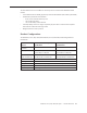
MacBook (13-inch, Early and Mid 2009) Contents Take Apart Manual Updates 8 General Information 9 What’s New 9 Product Configurations 10 New NVIDIA GeForce 9400M graphics processor 11 Liquid Submersion Indicator (LSI) Locations 12 Cable Connector Names on Logic Board 13 JST Connectors 13 Foam Sponges on the Logic Board 14 Logic Board Spring 14 Keyboard and Function Keys 15 Keycap Replacement 16 Tools 16 Temperature Concerns 17 Note About Images in This Manual 17 Serial Number Location 17 Transferring the Se
Trackpad Cable 46 Hard Drive Snubbers, Front and Rear 51 AirPort Extreme Card 54 MagSafe DC-In Board 57 Left Speaker 61 I/O Frame (with upper EMI shield) 64 Battery Connector with Sleep Switch 67 Hard Drive Connector Fan 71 77 Heatsink 80 Checking the Thermal Grease 84 Bluetooth Holder 87 Optical Drive 91 Handling Slot-Load Optical Drives 98 Removing a Stuck Disc from an Optical Drive 102 Optical Drive Cable 104 Bluetooth Antenna Board and Cable 107 Bluetooth Board 111 Bluetooth-to-Logic-Board C
Shims at Display Bezel Scoops 147 Clutch Block, Left 150 Clutch Block, Right 154 Clutch Caps 158 (Refer to “Clutch Block, Left” and “Clutch Block, Right”) 158 Display Module 159 Bottom Case 165 Clutch Cover 168 Bezel Scoops, Left and Right 174 LCD Panel 177 Antenna Receptors and Cables, Top and Left LCD Panel Assembly 182 187 Removal Procedure 189 Reinstallation Procedure 193 Spacers at Camera Bracket 201 Camera Assembly 203 LVDS Cable with USB Line 209 Microphone Cable 215 Inverter Board 222 Inve
Troubleshooting Aids and Tips 248 MacBook Firmware Updates 250 Software Troubleshooting Tips and Tools 251 Troubleshooting Steps 252 Symptom Charts 255 How to Use the Symptom Charts 255 AirPort 255 Temperature Issue 256 Memory 257 Power, Battery, or Startup Issue 258 Power-On Self Test (POST) Error Codes 265 Optical Drive 265 Keyboard and Trackpad 267 USB / FireWire Ports 267 Video 268 Sound Output 270 Applications 271 Block Diagram 273 Views External and Internal Views 275 Front: Keyboard and IR Wind
Service Source Take Apart MacBook (13-inch, Early 2009) © 2009 Apple Inc. All rights reserved.
Manual Updates Updated 12 July 2010 Take Apart: • Top Case/Display Bezel Kit: Added new topic describing how to order a kit that includes both a top case and a display bezel Views: • Exploded Views: Updated top case and display bezel part numbers Updated 14 May 2010 Take Apart > General Information: • Added new section “Keycap Replacement.” Additional Procedures • Deleted chapter; replaced by “Keycap Replacement” in Take Apart > General Information.
General Information What’s New The MacBook (13-inch, Early 2009) and MacBook (13-inch, Mid 2009) portable computers have a 1066 MHz frontside bus, 2 GB of standard memory (expandable to 4 GB), and a 2.0 or 2.4 GB processor, respectively. The main changes to the MacBook (13-inch, Mid 2009) from the MacBook (13-inch, Early 2009) are the following: • 800MHz RAM, compared with 667MHz for the (Early 2009) • New hard drives, from 160 to 500 GBs • New 2.
The main features and service differences from the previous non-aluminum MacBook models include: • A new NVIDIA GeForce 9400M graphics chip with 256 MB of VRAM (shared with system RAM) • Additional Liquid Submersion Indicators: –– three on the underside of the top case –– one on the logic board –– one on the battery cable connector • A backup battery which is no longer a separate part, but rather a surface mount capacitor built onto the underside of the logic board • Weight reduced to under 5 pounds Produc
New NVIDIA GeForce 9400M graphics processor The new NVIDIA GeForce 9400M graphics processor, with increased 256MB of DDR2 SDRAM (shared with main memory), speeds up graphic performance for movies, games, video, image editing and system graphics like Dashboard and Cover Flow.
Liquid Submersion Indicator (LSI) Locations To help determine accidental damage, the MacBook’s top case, logic board and battery cable connector include spill sensors called liquid submersion indicators (LSIs). These small white dots turn red when they come in contact with liquid, such as an accidental spill. There are three LSIs under the keyboard of the top case. Note that for research and engineering purposes the top case will now be a returnable 661- part instead of a 922- part.
Cable Connector Names on Logic Board To aid in servicing the computer, the logic board includes abbreviated names for connectors: BKLGHT = Inverter cable for backlight TEMP = Heatsink thermistor cable FAN = Fan cable BT = Bluetooth cable ODD = Optical drive flex cable LVDS = LVDS display cable HDD = Hard drive cable SPK = Left speaker cable SPK = Right speaker cable and subwoofer MIC = Microphone cable JST Connectors Remember to handle JST connectors carefully, using a black stick or finger to
Foam Sponges on the Logic Board The logic board has two foam sponges: one covering the inverter connector above the AirPort Extreme Card, and one covering the thermistor connector next to the heatsink. The foam sponges have a light adhesive on one side that keep them in place. While they can be removed for service, they must be reinstalled. Caution: When servicing the computer and before replacing the top case, make sure these two foam sponges are undamaged and in place.
Keyboard and Function Keys Images on the function keys include Exposé and Dashboard.
Keycap Replacement Service packages of 78 replacement keycaps are now available in the U.S. and Canada (U.S. version keyboard only) for designated MacBook and MacBook Pro computers. The packages allow you to replace individual keycaps rather than the entire top case. There are four different keycap packages, based on the color of the key and the type of keyboard (version D and S).
Temperature Concerns The normal operating temperature of this computer is well within national and international safety standards. Nevertheless, customers may be concerned about the generated heat. To prevent an unneeded repair, you can compare a customer’s computer to a running model, if available, at your repair site. For more information on temperature concerns and customer perception, refer to Knowledge Base article 30612 “Apple Portables: Operating Temperature.” http://docs.info.apple.com/article.
Transferring the Serial Number When replacing a top case, retain the customer’s top case until the repair is complete. Before installing the replacement top case, transfer the serial number from the original top case to the replacement. Caution: It is imperative that you copy the correct alphanumeric characters. Keep in mind that Apple serial numbers use the numbers 1 and 0 instead of the Roman letters “I” and “O.” 1.
Simplified Flowchart for Removing Modules Although this flowchart does not include every serviceable part, you can use it as a reference after becoming familiar with the detailed removal procedures.
Battery Tools • • Clean, soft, lint-free cloth Coin Part Location Preliminary Steps Warning: Always shut down the computer before opening it to avoid damaging the internal components or causing injury. After you shut down the computer, the internal components can be very hot. Let the computer cool down for 30 minutes before continuing.
Procedure 1. Shut down the computer. 2. Wait 30 minutes to allow the computer’s internal components to cool. 3. Unplug all external cables from the computer except the power cord. 4. Unplug the power cord. 5. Put on an ESD wrist strap. 6. Turn over the computer and place it on a soft cloth. 7. Use a coin to release the battery latch. Turn the coin a quarter turn clockwise to unlock the battery.
9. To install the replacement battery, tilt the foot end of the battery into the battery bay first. Then press and hold down the other end of the battery as you turn the coin to lock it into place. 10. Reassemble and test the computer.
RAM Door (L-Bracket) Tools • • • • Soft cloth ESD wrist strap and mat Magnetic Phillips #0 screwdriver Black stick (Apple part no. 922-5065) or other nonconductive nylon or plastic flatblade tool Preliminary Steps Before you begin, remove the battery.
Procedure 1. With the computer closed and upside down on a soft cloth, touch a metal surface inside the battery bay to discharge any static electricity. 2. Loosen—but do not try to remove—the three captive screws along the RAM door.
3. Holding the long end of the L-shaped RAM door, pivot it out from the battery bay. (If necessary, use a black stick to tilt it up and out of the battery bay.) Be careful not to bend it.
4. Replacement Note: Install the replacement RAM door by first aligning the short end at the notch near the hard drive opening. Replacement Note: Use a black stick, if necessary, to tuck in the EMI gaskets so they do not protrude from the edge of the battery bay. Make sure the three screws align with the holes in the bottom case before tightening them. 5. Reassemble and test the computer.
Memory (DIMMs) This computer comes with a minimum of 2 GB of 667 GHz Double Data Rate 2 (DDR2) Synchronous Dynamic Random-Access Memory (SDRAM) installed. It has two slots that can accept SDRAM Small Outline Dual Inline Memory Modules (SO-DIMMs). The slots are side-by-side on the logic board behind the RAM door. For best performance, memory should be installed as pairs with an equal memory card in each slot. The maximum amount of memory for this computer is 4 GB, with 2 GB DIMM installed in each slot.
Removal Procedure 1. Touch a metal surface inside the battery bay to discharge any static electricity. 2. Put on an ESD wrist strap. 3. In one swift motion, use one finger to move the lever to the left and release it. This swift motion ejects the memory card. Caution: The memory card eject levers are on a spring hinge that operates on a side-toside horizontal plane. The mechanism can be damaged if the lever is forced outside of that horizontal movement.
4. Holding the memory cards by the corners, slide them out from the battery bay. Important: Do not touch the gold connectors. Handle the card only by its edges. Note: A memory card might show a white residue when you remove it. This harmless substance acts as a lubricant when installing the memory card at the factory, but it is not required when reinstalling a memory card. Replacement Procedure 1. Align the memory card so that the gold connectors face the slot and the notch is on the left.
2. Use two fingers to push firmly on the edge of the memory cards. If there is a tight fit, installing the cards may take some force to ensure that they are fully inserted. Important: When the cards are fully inserted, the edges of the cards are nearly hidden, as shown by the recessed card on the right in the image below. 3. If the levers do not return to the closed position, move them to close them. 4. Reassemble and test the computer. 5.
Removing a Stuck Memory Card If a lever becomes inoperable and does not eject a memory card, you must remove the top case to access the stuck memory card. Follow this procedure only if the memory card is stuck and cannot be ejected by using the lever. 1. Follow the “Top Case” procedure in this chapter to remove the top case. 2. Notice the eject bars on each side of the memory card carrier. Use a black stick to push and slide the eject bar down the side of the carrier. 3.
Hard Drive Tools • • ESD wrist strap and mat Black stick (Apple part no.
Procedure 1. If the hard drive pull-tab is tucked in, use a black stick to unroll it. 2. Pull the tab straight out to slide the drive out from the rubber rails in the battery bay.
3. Hold the drive only by the sides when removing and replacing it. 4. Install the replacement hard drive, and reassemble and test the computer. Important: After a new hard drive replacement, you must update the operating system to Mac OS X version 10.5 or later. Replacement Note: If you are installing the hard drive while the top case is off, make sure the bottom case spring guide, shown below, is aligned with the notch in the bottom case.
Top Case (with Keyboard) Tools • • • • • • ESD wrist strap and mat Magnetic Phillips #0 screwdriver Magnetic Phillips #00 screwdriver (preferably with a long handle) Black stick (Apple part no. 922-5065) or other nonconductive nylon or plastic flatblade tool Access card (Apple part no.
Procedure Caution: To prevent scratches or other cosmetic damage to the computer housing, use a soft cloth as a protective layer when removing and installing the external screws. 1. With the computer upright, remove the two identical 5.5-mm long shoulder screws from the right side of the computer. Replacement Caution: When installing these top case screws, do not press on the area over the slot drive. The slot-drive bezel could be damaged with too much pressure. 2.
Turn over the computer, and on the outside of the bottom case, remove the three #0 Phillips screws: • Two 14-mm long screws near display hinge • One 11-mm long at center of bottom case Note: If the two 14-mm screws are tightly wedged in their holes, gently turn the unit over and use your fingernails or a sharp black stick to pry them out, being careful not to damage the cosmetic casing. Replacement Caution: Do not put one of the longer screws in the center screw hole or it will damage the logic board.
4. Notice the long row of #0 Phillips screws at the front edge of the battery bay. 5. Important: Remove only the four screws shown. Remove the 3-mm long identical screws as follows: Starting at the corner closest to the battery connector, skip the first screw, then remove the second, fourth, seventh, and ninth screw. Tip: To help remember the screw sequence, think of it as “2, 4, 7, 9 loosens the top case every time.” 6.
7. In the battery bay, use a long-handled screwdriver to remove the three #00 Phillips screws at the inner edge of the battery bay near where the RAM slots are located: • Two identical 3-mm long screws • One longer 4.5-mm long screw at the corner of the battery bay nearest the battery connector Because this is a recessed area, the screwdriver has to go in at an angle. Keep the screwdriver in line with the screw head as much as possible, especially to avoid stripping the screws.
10. With the top and right side gap opened, tilt up—but do not remove—the right edge of the top case. This motion releases the remaining snaps between the top case and bottom case, and the slot-load bezel clips become loose as the top case is tilted up.
11. Without straining the trackpad cable, carefully lift up the top case so you can see where the folded trackpad flex cable attaches to the logic board. 12. Use the flat end of a black stick to reach in and disconnect the trackpad cable.
13. Lift the top case up and away from the computer assembly. 14. Refer to the following notes to install the replacement top case, and reassemble and test the computer.
Replacement Note: The top case includes heatstaked keyboard, webbing, EMI shield, and attached trackpad cable. Replacement Note: Before replacing the top case, make sure to connect the trackpad flex cable to the logic board.
Replacement Note: Install the right side of the top case first (near the disc bezel). Then starting from the right, secure the snaps by pressing along the outer edge of the top case in a clockwise direction around the front and left side of the top case. Replacement Caution: When installing exterior and battery bay screws, apply light pressure to the top case to ensure that the top case fits to the bottom case without any gaps.
Top Case/Display Bezel Kit New Kit Available in July 2010 A new kit is available for top case replacement in the U.S. The kit contains: • top case with keyboard • display bezel Before Ordering Parts When replacing a top case or display bezel, order the new kit to replace both parts in one repair.
Trackpad Cable Tools • • ESD wrist strap and mat Black stick (Apple part no.
Procedure 1. Place the top case (keyboard side down) on a clean surface. Replacement Note: The folds in the trackpad cable and the areas that adhere to the top case should match the computer you are servicing; however, the cable on your computer might be slightly shorter. 2. Use a black stick to start to peel up the clear strip of tape.
3. Hold the trackpad cable in place as you peel up—but do not remove—the tape. 4. Peel up the mylar shield that protects the trackpad circuitry.
Note: The shape of the mylar shield may differ slightly. This one includes a squared-off tab: 5. Caution: The trackpad cable locking lever at the top of the connector is fragile. Use a black stick to carefully tilt up the lever until it is vertical (as shown by the detailed image on right). Replacement Note: When locking the trackpad cable lever, make sure it is completely closed, as shown by the detailed image on left below.
6. With the cable locking lever open, pull the cable down to remove it from the connector. 7. Carefully peel up the trackpad cable from where it adheres to the underside of the top case. 8. Install the replacement trackpad cable, and reassemble and test the computer.
Hard Drive Snubbers, Front and Rear Tools • • • • ESD wrist strap and mat Black stick (Apple part no.
Procedure Caution: The two hard drive snubbers are held in place on the bottom case frame with adhesive. When replacing the snubber(s), avoid touching the optical drive or the hard drive connector. Replacing the Front Snubber 1. Use a fine-point permanent marker to lightly mark the inside of the bottom case frame where the snubber begins and ends. 2. Starting at the end of the snubber that is farthest from the hard drive connector, use a black stick to peel off the snubber. 3.
Replacing the Rear Snubber 1. Use a fine-point permanent marker to lightly mark the inside of the bottom case where the snubber begins and ends. 2. Remove only the 4.5-mm long screw (not the 3.5 mm screw) at the optical drive. 3. Starting at the end of the snubber that is farthest from the hard drive connector, use a black stick to peel off the snubber. 4. If necessary, use a needlenose pliers or tweezers to remove remaining pieces of rubber that stick to the bottom case. Clean the area if necessary.
AirPort Extreme Card Tools • • • ESD wrist strap and mat Black stick (Apple part no.
Procedure Caution: When servicing the computer, be especially careful when working near the spring on the logic board. Although the spring is flexible, it can be inadvertently torn, bent, or broken if a cable gets caught on it. A logic board might be considered unusable with a damaged spring. Check the structural integrity of the spring before completing a repair. 1. Remove the 8.5-mm long screw (that also functions as the left speaker cable ground pin) from the upper right corner of the card.
card up and out of the card socket on the logic board. 4. Install the replacement AirPort Card, and reassemble and test the computer. Replacement Caution: When connecting the AirPort antenna cables, make sure the cables do not obstruct the gold spring on the logic board. If one of the cables were caught in the folds of the spring, the cable or spring could be damaged when the top case is installed.
MagSafe DC-In Board Tools • • • ESD wrist strap and mat Magnetic Phillips #0 screwdriver Black stick (Apple part no.
Procedure 1. Place a black stick under the DC-in connector cables to help disconnect the connector, then pull the connector away from its connection on the logic board. 2. Remove the 3-mm long screw from the MagSafe DC-in board. Caution: The MagSafe DC-in port is magnetic. Be careful that it doesn’t pick up screws or other small metallic parts.
3. From the port side, use a black stick to help tilt up the MagSafe DC-in board as shown, then extract it out from under a lip on the logic board, pulling straight out at an upward angle. Replacement Note: Make sure the folded side of the EMI shield fits over the I/O frame rib so that the rib is sandwiched between the flanges of the EMI shield. Replacement Note: If installing a new MagSafe DC-in board, first peel off the protective membrane from the MagSafe DC-in board.
Replacement Note: Check that there are no bent EMI fingers on the shield covering the port area. Replacement Note: Check the port side of the bottom case to make sure the MagSafe DC-in port is level with the port opening.
Left Speaker Tools • • • ESD wrist strap and mat Magnetic Phillips #0 screwdriver Black stick (Apple part no.
Procedure Note: Images shown below may differ from the actual computer you are servicing; however, the steps and sequence are the same. 1. Optional: Disconnect the MagSafe connector cable. 2. Remove the 8.5-mm long screw from the speaker body and the 8.5-mm long ground screw at the upper right corner of the AirPort Extreme Card. 3. Disconnect the speaker cable from the logic board. 4. Route the disconnected speaker cable underneath the AirPort cables.
5. Tilt up the speaker from the bottom case, and route the cable underneath the MagSafe cable (if still connected). 6. Install the replacement speaker cable, and reassemble and test the computer. Replacement Note: To prevent a pinched cable, make sure the cable is routed as shown.
I/O Frame (with upper EMI shield) Tools • • • ESD wrist strap and mat Magnetic Phillips #0 screwdriver Black stick (Apple part number 922-5065) or other nonconductive nylon or plastic flatblade tool Preliminary Steps Before you begin, remove • Battery • RAM door • Top case with keyboard Part Location MacBook (13-inch, Early 2009) Take Apart — I/O Frame 64
Procedure 1. Disconnect the MagSafe connector from the logic board, and remove the four identical 8.5mm long screws from the I/O frame. 2. Note how the EMI shield on the I/O frame interlocks with the shield over the ports. Make sure that the shield does not stick to the ports when removing the I/O frame. 3. Tilt up the I/O frame to remove it from the computer assembly.
4. Note that the I/O frame includes the EMI shield. Be careful not to bend the shield as you remove or install it. 5. Install the replacement I/O frame, and reassemble and test the display.
Battery Connector with Sleep Switch Tools • • • ESD wrist strap and mat Magnetic Phillips #0 screwdriver Black stick (Apple part no.
Procedure Caution: Do not touch the raised section of the sleep switch connector. It is quite fragile and could break. 1. Remove the two 4.5-mm long shoulder screws from the frame at the battery connector. Replacement Caution: Make sure the screws are the proper length. A longer screw could damage the board. 2. Tilt up the battery connector end of the board. 3. Avoid touching the raised section of the sleep switch connector; it is fragile and could break.
4. Important: When replacing the battery connector/sleep switch, make sure the arrangement of pins on the connector exactly match the pin openings on the logic board. I 5. To avoid bending the pins on the sleep switch connector card, make sure you squarely align the pins over the logic board and keep the connector card level when installing it. 6. Install the “pins” end of the sleep switch connector first; then install the battery connector and screws.
7. Install the replacement battery connector with sleep switch, and reassemble and test the computer. Caution: To avoid pinching the cable, the battery connector cable must be properly tucked into the cable channel, as shown by the image on the left, below: Replacement Note: With the part fully installed, check that the battery connector can be wiggled to allow for movement of the battery. If the connector is completely still when grasped, loosen the screws slightly.
Hard Drive Connector Tools • • • ESD wrist strap and mat Magnetic Phillips #0 screwdriver Black stick (Apple part no.
Procedure 1. Disconnect the optical drive flex cable from the logic board. 2. Use the pull tab to disconnect the LVDS connector cable.
3. Use the pull tab to disconnect the hard drive cable connector. 4. Pull up the hard drive connector cable that runs along the bottom edge of the optical drive. Note the four cable routing guides when reinstalling the cable.
5. Remove the two 6-mm long screws from the hard drive connector at the right front side of the computer. 6. Carefully lift up the hard drive connector from the bottom case. This action automatically disconnects the hard drive board from the sleep LED/IR receiver flex cable.
Replacement Caution: Note the tiny connector at the end of the hard drive board. It connects to the sleep LED/IR receiver board at the front right corner of the computer via a tiny flex cable. To reinstall the flex cable, first peel up the end of the snubber to access the length of the flex cable. Carefully peel up the flex cable from its adhesive. Using a black stick, tilt up the tiny flex cable at the right corner.
7. Install the replacement hard drive connector, and reassemble and test the computer.
Fan Tools • • • ESD wrist strap and mat Magnetic Phillips #00 screwdriver Black stick (Apple part no.
Procedure 1. Peel up the strip of tape that overlaps the fan near the optical drive. 2. Remove the screws from the fan: • 6.5-mm long screw from the upper left • 3.5-mm long screw from the upper right (normally hidden underneath the cable bundles) 3. Disconnect the fan cable from the logic board.
4. Tilt up the fan and remove it from the logic board. 5. Peel away the adhesive foam that overlaps the fan and the heatsink. Replacement Note: Be sure to install the strip of adhesive foam before reassembling the computer. 6. Install the replacement fan, and reassemble and test the computer. Replacement Note: Make sure the cables are fully tucked in the channel between the fan and the optical drive. Reapply the tape or apply new tape.
Heatsink Tools • • • • • • ESD wrist strap and mat Magnetic Phillips #0 screwdriver Black stick (Apple part no.
Procedure Note: Though photos in this section may vary from the actual model you are repairing, the procedure remains exactly the same. Important Note: Replacement heatsink modules have the thermal grease pre-applied. However, if you are reusing the unit’s existing heatsink, you must apply new thermal grease. See the section “Checking the Thermal Grease” at the end of this chapter. 1. Remove the four identical 8-mm long screws from the heatsink.
2. (For MacBook (13-inch, Early 2009)): The heatsink on the unit you are repairing may or may not have a thermal sensor cable (see photo). If not, skip to step 3. • If the thermal sensor is present, first remove the black square foam pad on the logic board connector, and set it aside for re-use. • Use a black stick to disconnect the JST connector straight up from the logic board.
3. To remove the existing heatsink, hold the lower end to tilt and loosen it from the logic board. 4. Important: Anytime the heatsink is removed (even if it is to replace another module), check the thermal grease as described in the next section. MacBook (13-inch, Early 2009) Replacement Note: The replacement heatsink may have a thermal sensor cable attached (even if the defective heatsink did not).
Checking the Thermal Grease Warning: Whenever the heatsink is separated from the logic board (even if you are installing the same heatsink or board), the thermal grease must be checked and possibly replaced. Failure to do so can cause the computer to overheat and be damaged. 1. Caution: This step is required when the heatsink and logic board are removed to replace a later part (such as the bottom case) and the same heatsink and logic board will be reinstalled in the computer.
2. Caution: The syringe steps for this procedure are required only when the heatsink and logic board are removed to replace a later part (such as the bottom case) and when no new heatsink with pre-applied thermal grease will be installed. Refer to the heatsink conditions in step 1 for details before attempting to replace the thermal grease. Note the contents of the syringe of thermal grease. Important: One syringe (922-7144) contains 0.3 to 0.35 cubic centimeters (cc) of thermal grease.
4. While centering the heatsink pads over the two chips, lower the heatsink onto the logic board and press on the areas where the screw brackets on the heatsink meet the standoffs on the board. Make sure the heatsink is level on the board before installing the screws. 5. Install the heatsink screws in the order shown, and reassemble and test the computer. Note: Make sure the heatsink includes the gray, adhesive sponge strip that sticks to and runs along the top right section of the copper pipe.
Bluetooth Holder Important: The Bluetooth holder is included with a replacement optical drive and should not be removed unless it is damaged or no longer sticks to the optical drive housing. Tools • • • ESD wrist strap and mat Any standard size CD or DVD disc Black stick (Apple part no.
Procedure 1. Insert a CD or DVD disc half way into the slot drive to help support the drive and prevent damage. 2. Use a black stick to slide out the Bluetooth board from its holder.
3. Warning: To prevent damage to the optical drive, do not touch or press anywhere else on the drive. 4. Use a black stick to carefully pry up the Bluetooth holder from the top of the optical drive. Make sure you use as little pressure as possible to prevent damage to the drive. Replacement Note: Peel off the adhesive backing from the Bluetooth holder and apply it to the drive where shown. Press the holder lightly to make sure it adheres to the drive.
5. Install the replacement Bluetooth holder, remove the optical drive disc, and reassemble and test the computer.
Optical Drive Tools • • • ESD wrist strap and mat Magnetic Phillips #0 screwdriver Black stick (Apple part no.
Procedure 1. With the computer assembly on a clean, scratch-proof surface, locate the Bluetooth board and holder at the upper right corner of the drive. Note that the Bluetooth holder stays with the drive and is included with a replacement optical drive. 2. Tilt up the Bluetooth board from the Bluetooth holder. 3. Disconnect the optical drive flex cable from the logic board.
4. Peel up the tape from the optical drive. 5. Use a black stick to move aside the cables to reach the 3-mm long screw securing the mounting bracket for the drive. You might first need to disconnect the ground screw by the speaker to loosen the cables enough to remove the mounting bracket screw. 6. Use a black stick to slide the mounting bracket forward (away from the body of the drive and toward the fan) to disengage it.
7. Slide out the hard drive, and set it aside. 8. Remove the two screws along the bottom edge of the drive at the hard drive snubber. (If the snubber is blocking one of the screws, carefully peel up the snubber.) Replacement Note: Make sure you install the longer screw (4.5 mm) closest to the right side of the bottom case.
9. Lift up the cable that runs between the drive and the snubber at the lower edge of the optical drive. 10. Warning: Handle the optical drive at the side edges only. Do not touch or press anywhere else on the drive. Refer to the next section, “Handling Slot-Load Optical Drives.” 11. Grasp the optical drive flex cable, and use it as a pull tab as you tilt up the optical drive just enough to clear the bottom case frame. Be careful where it can catch on cables, and slide it away from the rear frame.
Replacement Note: Make sure the mounting bracket on the optical drive is pushed in before placing the optical drive in the bottom case. Replacement Note: Reverse the screw order: install snubber screws first.
12. Before installing the optical drive, make sure the cables on the bottom case are routed as shown. 13. Install the replacement optical drive and reassemble and test the computer. (Note: The L-shaped strip of black tape is for controlling vibration; do not remove the tape.) Important: For best performance after a new optical drive replacement, be sure to update the operating system to the latest Mac OS X version.
Handling Slot-Load Optical Drives Follow the instructions in this section carefully. This procedure shows how to handle slot-load optical drives when they are outside the computer. • Observe ESD (electrostatic discharge) guidelines when handling optical drives.
• Handle the drive only by the sides and back edge. • Do not touch the front of the drive.
• Do not press on the drive or lift it by the top and bottom cover. • Do not handle the drive by the gull wing edge only.
• When storing optical drives, use approved packaging boxes. Never stack loose drives. • When returning a defective optical drive, use the original packaging and an antistatic bag. Pack only one drive per box.
Removing a Stuck Disc from an Optical Drive Important: This procedure applies only to 9.5-mm and 12.7-mm slot-load optical drives. 1. Remove the four identical screws that hold the top cover to the drive. 2. Slide the top cover approximately 2 mm toward the back of the drive. Lift up the top cover to remove it.
3. Check the placement of the disc. It is either clamped to the turntable at the center of the disc, or it is wedged under one or more posts at the outer edge of the disc. 4. Holding the edge of the disc, press on the center clamp or hold the posts steady as you remove the disc from the drive. Important: Do not touch any key components located near the disc. 5. Replace the top cover on the drive so that the small hooks on the top cover fit into the slots on the bottom cover.
Optical Drive Cable Tools • • ESD wrist strap and mat Black stick (Apple part no.
Procedure Warning: Handle the optical drive at the side edges only. Do not touch or press anywhere else on the drive. 1. With the optical drive on a clean, scratch-proof surface, use a black stick to evenly pry up the cable connector from the drive. 2. Carefully pry up the thin strip of black tape that overlaps the optical drive cable. Then pry up the connector from the drive.
3. Remove the optical drive cable. 4. Install the replacement optical drive cable, and reassemble and test the computer. Note: both sides of the cable may have an adhesive mesh strip. Note: the cable might also include a mylar strip. If attached, do not remove it.
Bluetooth Antenna Board and Cable Tools • • • ESD wrist strap and mat Magnetic Phillips #0 screwdriver Black stick (Apple part number 922-5065) or other nonconductive nylon or plastic flatblade tool Preliminary Steps Before you begin, remove • Battery • RAM door • Top case with keyboard • Optical drive Part Location MacBook (13-inch Early 2009) Take Apart — Bluetooth Antenna Board and Cable 107
Procedure 1. Remove the 3-mm screw from the right speaker. 2. Without straining the speaker cable, tilt up the speaker and unroute it from the right corner of the frame.
3. Unroute the thin Bluetooth cable and the black speaker cable.
4. Using a black stick, disconnect the Bluetooth antenna cable from the lower right corner of the Bluetooth board. Pry the connector straight up. 5. Install the replacement Bluetooth antenna board and cable. Replacement Caution: To prevent a pinched or damaged cable, make sure the cable is routed through the cable guides, as shown.
Bluetooth Board Tools • • ESD wrist strap and mat Black stick (Apple part number 922-5065) or other nonconductive nylon or plastic flatblade tool Preliminary Steps Before you begin, remove • Battery • RAM door • Top case with keyboard • Optical drive Part Location MacBook (13-inch Early 2009) Take Apart — Bluetooth Board 111
Procedure Caution: During this procedure and when applying a replacement Bluetooth board, do not press on the center of the board. The only acceptable area to press on is the right corners of the board near the locator pin and the Bluetooth antenna cable connector. Important: The Bluetooth board is adhered to the bottom case with double-sided tape. Before removing the Bluetooth board, note the cable routing near the Bluetooth board. 1.
Replacement Note: Without straining the Bluetooth-to-logic board cable, slide a black stick underneath the board sleeve, and insert and press the connector to secure it to the board. Replacement Note: Connect the Bluetooth-to-logic board cable first before adhering the board to the bottom case. Then install the Bluetooth antenna cable, and make sure the cable exits toward the upper right corner of the bottom case. Replacement Note: Make sure the upper right corner of the board fits over the locator pin.
Bluetooth-to-Logic-Board Cable Tools • • ESD wrist strap and mat Black stick (Apple part no.
Procedure Note: The photography below may differ from the actual unit you are repairing; however, the actual procedure remains the same. Important: During this procedure and when applying a replacement Bluetooth-to-logic-board cable, do not press on the center of the Bluetooth board. The only acceptable area to press on is the right corners of the board near the locator pin and the Bluetooth antenna cable. 1. Carefully move aside any cables that block the Bluetooth-to-logic-board cable path.
3. With the Bluetooth cable disconnected from the Bluetooth board, route the Bluetooth cable underneath the silver microphone cable. 4. Use a black stick and your finger to disconnect the connector from the logic board. Note: Ensure the JST connector stays level as you disconnect it and later reinstall it.
5. Install a replacement Bluetooth-to-logic-board cable, and reassemble and test the computer. Replacement Note: With the cable attached to the Bluetooth board, install the cable under the subwoofer tabs before routing the cable to the logic board. Make sure the cable routing appears as shown before reconnecting the remaining cables to the logic board.
Subwoofer with Right Speaker Cable Tools • • • ESD wrist strap and mat Magnetic Phillips #0 screwdriver Black stick (Apple part number 922-5065) or other nonconductive nylon or plastic flatblade tool Preliminary Steps Before you begin, remove • Battery • RAM door • Top case with keyboard • Optical drive Part Location MacBook (13-inch Early 2009) Take Apart — Subwoofer with Right Speaker Cable 118
Procedure Warning: The subwoofer cone is a sensitive device. Avoid touching the subwoofer cone. 1. Note the cable routing for the right speaker, and remove the 3.5-mm long screw at the speaker. 2. Tilt up the speaker.
3. Tilt up the right speaker from the top right corner of the computer assembly, and without straining the speaker cable, unroute it from the cable guides. 4. Remove the three identical 3-mm long screws from the subwoofer, and peel up the tape from the bottom case.
5. Warning: The subwoofer cone is a sensitive device. Avoid touching the subwoofer cone. To prevent excessive pressure on the subwoofer body, hold it by the edges as you perform this step. Unroute the speaker cable, and while holding the sides of the subwoofer, move the subwoofer body away from the rear panel. 6. Separate the subwoofer ground tab from underneath the microphone ground tab. 7. Disconnect the 4-pin speaker cable from the logic board connector, just over the memory card slots.
8. Replacement Note: When connecting the right speaker cable to the logic board, make sure the cable runs securely • over the right memory slot • between the optical drive cable connector and the LVDS cable connector • under the Bluetooth connector • between the fan and the midframe 9. Replacement Note: Before installing the subwoofer, check the bottom case to make sure the microphone cable is to the right of the LVDS cable, between it and the Bluetooth board. 10.
11. Install the replacement subwoofer with right speaker cable, and reassemble and test the computer.
Midframe Tools • • • ESD wrist strap and mat Magnetic Phillips #0 screwdriver Black stick (Apple part number 922-5065) or other nonconductive nylon or plastic flatblade tool Preliminary Steps Before you begin, remove • Battery • RAM door • Top case with keyboard • Optical drive Part Location MacBook (13-inch Early 2009) Take Apart — Midframe 124
Procedure 1. Note the orientation of the cables that route over the midframe. 2. Remove the screws: • three 7.5-mm long screws (middle and each end of the midframe) • 3-mm long ground screw • 3-mm long fan screw Warning: The subwoofer cone is a sensitive device. Avoid touching the subwoofer cone. 3. Without straining the cables, use a black stick to hold the cables aside as you pivot the midframe to remove it from the bottom case. 4.
Logic Board Tools • • • • • • • ESD wrist strap and mat Magnetic Phillips #0 screwdriver Black stick (Apple part no.
Part Location Procedure Caution: When servicing the computer, be especially careful when working near the gold spring on the logic board, located above the AirPort Extreme Card. Although the spring is flexible, it can be inadvertently torn, bent, or broken if a cable gets caught on it. A logic board might be rendered unusable with a damaged spring. Check the structural integrity of the spring before completing a repair.
1. Disconnect the optical drive flex cable from the logic board. 2. Without straining the optical drive flex cable, pull the pull-tab to disconnect the LVDS cable from the logic board.
3. Disconnect the following connectors from the logic board: • Bluetooth cable JST connector (Note: Make sure use your finger and a black stick to keep the connectors level when disconnecting them.) • hard drive cable connector. 4.
5. Place a heavy box behind the display to help support it (refer to “Clutch Block, Left” for more details). Disconnect the inverter cable, and remove the following: • 10.5-mm long thick-stemmed outer screw, closest to the left corner of the bottom case • 5.5-mm long thick-stemmed middle screw • 8-mm long thin-stemmed inner screw, closest to the antenna cables • 3.5-mm long screw from the upper right area of the board • foam sponge over inverter connector 6.
7. Remove the left clutch block and clutch cap, and carefully move aside any cables that overlap the logic board. Replacement Note: When reinstalling the clutch block, refer to “Clutch Block, Left” in this chapter. 8. Holding the logic board by its right side, tilt it up, and with a small rocking motion, remove it at an angle away from the I/O ports. You might find it helpful to use a black stick between the side of the bottom housing and the ports.
9. If you are installing a new logic board, transfer the following parts to the replacement board: • Tape at the edge of the board between the inverter connector and the large chip • AirPort Extreme Card • Memory cards • I/O shield 10. Before installing the logic board, make sure the gold spring is intact (not bent or broken).
11. Before installing the logic board, check the locator pins on the bottom case. Make sure the two openings in the logic board fit over the “+-shaped” locator pins. 12. Warning: Whenever the heatsink is separated from the logic board (even if you are installing the same logic board or heatsink), the thermal grease must be checked and possibly replaced. Failure to do so can cause the computer to overheat and be damaged. Refer to “Checking the Thermal Grease” in the Heatsink section. 13.
Display Bezel Tools • • • ESD wrist strap and mat Black stick (Apple part number 922-5065) or other nonconductive nylon or plastic flatblade tool Access card (Apple part number 922-7172) Preliminary Steps None Part Location MacBook (13-inch Early 2009) Take Apart — Display Bezel 134
Removal Procedure 1. With the display open wider than a 90-degree angle, run an access card along the outer sides and top edge of the bezel where it meets the display rear housing.
2. To loosen the bottom of the bezel, run a black stick along the inner edge where the bezel meets the LCD frame. Do not touch the display face. Note: If you have a plastic sheet that can protect the LCD panel, cover the display face. 3. Lift off the bezel. 4. Check for any mounting clips around the LCD frame that pop off or appear to be missing.
5. Return any clips back into the bezel brace. 6. If any of the mounting clips are difficult to install, check that they are structurally sound. You can order a kit of replacement clips if necessary. 7. Install the replacement bezel (first see notes in the Replacement Procedure), and reassemble and test the computer.
Replacement Procedure Important: Before installing a replacement bezel, be sure to check the camera area, and peel off the dust cover film that comes with a new bezel. Replacement Caution: The lower corners of the bezel include mounting hooks that differ in design from the snaps at the top and sides of the bezel. Incorrectly installing this area of the bezel can result in bent hooks and a bezel gap that would require bezel replacement. These hooks must be installed as follows.
1. Caution: To install the bezel, start at the top near the camera first. Match the two locator pins inside the bezel to the holes in the top center of the display assembly. 2. Press to secure the top of the bezel.
3. With the camera area secured, bend up the bottom of the bezel to hook the bottom edge of the bezel. 4. Press along the outer frame of the bezel to secure it to the display assembly.
Bezel Mounting Clips Tools • • • ESD wrist strap and mat Clean, soft, lint-free cloth Jeweler’s flatblade screwdriver Preliminary Steps Before you begin, remove • Display bezel Part Location MacBook (13-inch Early 2009) Take Apart — Bezel Mounting Clips 141
Removal Procedure Caution: When working near the bezel brace, cover the LCD panel with a soft cloth to avoid scratching the display. 1. Use a jeweler’s flatblade screwdriver to pry up the mounting clip. • If you are removing the clip from the bezel brace, pry it up from one of the narrow ends. • 2. If you are removing the clip from the display bezel, pry it up from one of the wide sides. Make sure no plastic remnants are left in the bezel brace opening from an old clip.
Replacement Procedure 1. Closely inspect the two hooks on the replacement mounting clip. Make sure the hooks are intact at a 90-degree angle. 2. Insert one end of the clip so that its hook catches on the bezel brace opening. While holding that end in place, use a jeweler’s flatblade screwdriver to tuck in the other hook. Note: You might need to bow the clip slightly to get it to fit.
3. Press the clip into place so that it is level with the bezel brace. 4. Make sure all twelve clips fit correctly in the bezel brace and that no clips remain on the inner side of the display bezel. 5. Install the replacement mounting clips, and reassemble and test the computer.
Spacers at Bezel Scoops Tools • • • Soft cloth ESD wrist strap and mat Black stick (Apple part number 922-5065) or other nonconductive nylon or plastic flatblade tool Preliminary Steps Before you begin, remove • Display bezel Part Location MacBook (13-inch Early 2009) Take Apart — Spacers at Bezel Scoops 145
Procedure 1. Note the placement of the two spacers that attach to the LCD panel frame with double-sided adhesive. Replacement Note: Position the replacement spacers vertically so that they fit into the space between the lower end of the bezel brace and the bezel scoop, but they should not extend past the outer edge of the display hinge. 2. Using a black stick, remove the spacers. 3. Install the replacement spacers above the bezel scoops, and reassemble and test the computer.
Shims at Display Bezel Scoops Tools • • • Soft cloth ESD wrist strap and mat Black stick (Apple part number 922-5065) or other nonconductive nylon or plastic flatblade tool Preliminary Steps Before you begin, remove • Display bezel Part Location MacBook (13-inch Early 2009) Take Apart — Shims at Display Bezel Scoops 147
Procedure 1. Note the horizontal placement of the shims that attach to the bottom corners of the LCD panel frame with double-sided adhesive. Replacement Note: Make sure the replacement shims fit into the space between the bottom edge of the LCD panel frame and the slot in the display rear housing.
2. Make sure the outer edge of the horizontal shim is approximately 3 mm away from the spacer, and the outer edge of the shim aligns with the outer edge of the LCD panel. 3. Install the replacement shims, and reassemble and test the computer.
Clutch Block, Left Tools • • • • ESD wrist strap and mat Black stick (Apple part no.
Procedure 1. Open the display and lean it against a stack of books or boxes that can support it when it is loosened from the display hinge. 2. Remove the screws from the left clutch block: • 10-mm long thick-stemmed outer screw, closest to the left corner of the bottom case • 6-mm long thick-stemmed middle screw • 6-mm long thin-stemmed inner screw, closest to the wireless cables.
3. Remove the left clutch block from the computer assembly. Note: Although the following image shows some cables disconnected, do not disconnect them. 4. Notice that the left clutch cap comes loose when the clutch block is removed. Make sure the left clutch cap is fitted into the clutch block, and hold it in place when replacing the clutch block. 5. If you are installing a new left clutch block, make sure there is a mesh pad on the flip side.
Replacement Note: Notice how the inverter cable and wireless antenna cables are routed around the left display hinge. Make sure they are routed as shown and cannot be pinched when the clutch cap and clutch block are installed. Replacement Note: If you are replacing the left and right clutch blocks as a pair, install the screws in an alternating sequence so that the outer screws of each clutch cap are installed first, followed by the remaining screws.
Clutch Block, Right Tools • • • • ESD wrist strap and mat Black stick (Apple part no.
Procedure Important Note: The photography below may differ from the actual unit you are repairing; however, the actual procedure remains the same. 1. Remove the screws from the right clutch block: • 10-mm long thick-stemmed outer screw, closest to the right corner of the bottom case • 6-mm long thick-stemmed middle screw • 3-mm long thin-stemmed inner screw 2. Use a black stick or finger to remove the right clutch block from the computer assembly.
Replacement Note: Tilt the left end of the right clutch block into the rear panel first so that the clutch cap engages with the bottom case. Then make sure the screw holes are aligned properly before installing the screws. Note: Unlike the left clutch block, there is no mesh pad on the right clutch block. Replacement Note: Notice how the right clutch cap comes loose as soon as the clutch block is removed.
Replacement Note: If you are replacing the left and right clutch blocks as a pair, install the screws in an alternating sequence so that the outer screws of each clutch cap are installed first, followed by the remaining screws. Replacement Note: The right clutch cap and left clutch cap are not the same. The right clutch cap is pictured below.
Clutch Caps (Refer to “Clutch Block, Left” and “Clutch Block, Right”) MacBook (13-inch Early 2009) Take Apart — Clutch Caps 158
Display Module Note: Although the display module is not offered as an available part, removing it is required to access all internal display parts (except the bezel). Tools • • • • ESD wrist strap and mat Black stick (Apple part no.
Part Location Procedure 1.
2. Remove the 3-mm ground screw that secures the cables to the midframe. Warning: The subwoofer cone is a sensitive device. Avoid touching the subwoofer cone. 3. Carefully unroute the LVDS cable and microphone cable from under the subwoofer tabs in the bottom case.
4. Near the right hinge, remove the 3-mm long ground screw that anchors the LVDS cable to the upper right corner of the bottom case. Note: The photography below may differ from the actual unit you are repairing; however, the actual procedure remains the same. 5. Near the left hinge, disconnect the inverter cable.
6. Holding the display module at the bezel, lift the module off of the computer assembly. 7. Install the replacement display module, and reassemble and test the computer. Replacement Note: When installing the display, note how the cables are routed at the right side of the clutch barrel—the LVDS cable and microphone cable wrap around the back of the clutch barrel and are routed into the bottom case.
Replacement Note: The microphone cable routes under the LVDS cable. Replacement Note: Make sure that no cables can be pinched when installing the LVDS cable ground screw.
Bottom Case Note: The bottom case includes the following parts: • Feet that are heat-staked, so they are not removable • Three integral frames: slot-load bezel frame, front bay frame, and rear frame • Infrared (IR) sensor board in the front right corner • Snubbers for hard drive Tools • • • • Soft cloth ESD wrist strap and mat Magnetic Phillips #0 screwdriver Black stick (Apple part no.
Part Location Procedure When the parts listed in the “Preliminary Steps” have been removed, the remaining part is the bottom case. Replacement Note: Make sure the bottom case is clean and free of dust before assembling the computer.
Important: Make sure that the mushroom-shaped rubber standoff is in place where shown before installing the logic board. Note: If the rubber standoff comes loose, use needlenose pliers to install it.
Clutch Cover Tools • • • • ESD wrist strap and mat Magnetic Phillips #0 screwdriver Black stick (Apple probe tool, part no.
Part Location Procedure Important: The display cables might catch on the clutch cover at you remove it, so proceed slowly to prevent any cable damage. 1. Notice the cable exits points at each side of the clutch. Refer to the cable arrangement shown when reinstalling the clutch cover.
2. With the display assembly face up, remove the three 4-mm long screws along the top edge of the clutch cover.
3. Slide an access card along the outer edge of the clutch cover to loosen it from the display rear housing. 4. Unsnap both ends of the clutch cover using a black stick.
5. Holding the bundled display cables at each end of the clutch cover, carefully unwrap them to help raise up the clutch cover. 6. Without straining cables, carefully pull the clutch cover off of the display assembly. 7. Install the replacement clutch cover, and reassemble and test the computer. Replacement Note: The inner channel of the clutch cover includes a foam pad that helps stabilize the inverter board. Do not remove it.
Replacement Note: Be careful when securing the snaps at each end of the clutch cover. Cables wrap around the barrel at the hinges, but tucking in the cables just right is difficult, and the cables are subject to pinching damage when the clutch cover is installed. Replacement Caution: Notice how the display cables are wrapped around the clutch. Check that they are wrapped as shown before reassembling the computer.
Bezel Scoops, Left and Right Tools • • ESD wrist strap and mat Black stick (Apple probe tool, part no.
Procedure 1. With the bezel spacers removed, use a black stick to loosen the outer edge of the bezel scoop and push it toward the display face. Repeat for the other bezel scoop. Replacement Note: Before replacing the bezel scoops, make sure that the cables that are routed under the bezel scoops have no slack. Refer to the following images for the correct cable routing.
Replacement Note: On the underside of each bezel scoop, note that the three raised tabs match up with the three slots in the display hinge. Align the tabs to the slots. Replacement Note: With the cables tucked in, slide on the bezel scoop.
LCD Panel Tools • • • • • Soft cloth ESD wrist strap and mat Magnetic Phillips #0 screwdriver Black stick (Apple part no.
Part Location Procedure 1. With all of the preliminary steps performed, turn over the LCD panel and check for any remaining strips of tape.
2. Install the replacement LCD panel, and reassemble and test the computer. Replacement Note: When reassembling the computer, make sure the LCD cable is bent, but not pinched or damaged.
Replacement Note: Start by connecting the LVDS cable and USB flex line first. Then place the tape before continuing with the rest of the reassembly. Important: Notice the correct horizontal placement of the tape. If placed vertically, the tape can be visible through the Apple logo on the display rear housing. Before reassembling the display, check the back of the LCD panel to make sure the tape is placed horizontally, as shown.
With the LCD panel in the rear housing, but before securing the panel screws, hold the panel in place and tilt up the housing. Shine a bright light at the center of the screen, and check that the Apple logo shows no discoloration. If discoloration is visible, carefully reapply the tape away from the logo area. Once fully assembled, turn on the computer to verify the color uniformity of the logo. Replacement Note: Make sure the LVDS cable is correctly matched with its corresponding LCD panel:.
Antenna Receptors and Cables, Top and Left Tools • • • • • Soft cloth ESD wrist strap and mat Magnetic Phillips #0 screwdriver Black stick (Apple part no.
Part Location Procedure Notice that the antenna cables are two separate cables (black and gray) that run along the left front side of the LCD panel brace. The gray cable is also routed over the top corner of the LCD panel. 1. Carefully unroute the cables from the left brace.
2. Remove the three identical 3-mm long screws from the left brace. 3. Rotate the top corner of the LCD panel and remove the 3-mm long screw from the left brace and camera bracket.
4. Slightly lift up the end of the camera bracket to free the locator pin on the end of the left brace. Replacement Note: To avoid straining cables, be sure to align the locator pin and hole before sliding on the left brace. 5. Move the left brace away from the LCD panel assembly, and use a jeweler’s flatblade screwdriver placed underneath the antenna receptor to carefully pry up the antenna receptor.
Replacement Note: Secure the antenna receptors by placing them over the recessed brace area and pressing only on the metal fold. You will hear an audible snap when they are installed. 6. Install the replacement antenna cables, and reassemble and test the computer.
LCD Panel Assembly Important: Although the LCD panel assembly is not an available subassembly part, it must be removed to replace other display parts. Tools • • • • • Soft cloth ESD wrist strap and mat Magnetic Phillips #0 screwdriver Black stick (Apple probe tool, part no.
Part Location MacBook (13-inch Early 2009) Take Apart — LCD Panel Assembly 188
Removal Procedure 1. Important: Study the cable routing around each hinge carefully. When reinstalling the LCD panel assembly for your first time, this can be a tricky area Note: Although the images show the inverter board installed, it should be removed previously as listed in the preliminary steps.
2. Following the order shown, remove the twelve identical 4.5-mm long screws around the frame of the LCD panel. Caution: To prevent scratches or other cosmetic damage to the display housing, use a soft cloth as a protective layer when removing the screws.
3. Remove the 3-mm long ground screw from the left hinge. Note: Although the images show the inverter board installed, it should be removed previously as listed in the preliminary steps. 4. Starting at the bottom corners, lift the LCD panel with frame and attached cables off of the display rear housing.
Note: The top of the camera bracket includes four thin, clear strips of double-sided tape. These are the camera spacers that are discussed later in this chapter. Be sure to reinstall them if they become loose. Note: The magnets located in the display rear housing may come loose while lifting out the LCD panel assembly from the display rear housing. Don’t lose the magnet pairs (on top corners) that function as the latch.
5. Set aside the LCD panel assembly so that the display is face-up if you are replacing any of its parts or any parts remaining in the display rear housing. 6. Reinstall the LCD panel assembly as follows.
1.
2. Important: Notice the correct horizontal placement of the tape. If placed vertically, the tape can be visible through the Apple logo on the display rear housing. Before reassembling the display, check the back of the LCD panel to make sure the tape is placed horizontally, as shown. With the LCD panel in the rear housing, but before securing the panel screws, hold the panel in place and tilt up the housing.
3. Check the display rear housing to make sure it includes the three magnets: • Sleep magnet on side • Two magnet pairs on top 4. Important: Insert the top corners of the LCD panel assembly into the display rear housing first. Use the notch in each bezel brace to help hold the cables in position. Then, before you set the LCD panel assembly into the display housing, route the cables under the bezel brace between the housing and the display hinge.
5. Set the magnets back into place if they come loose during this step. 6. With the top corners secured, tilt up the bottom corners or the LCD panel assembly to route the antenna receptor cables and microphone cable around the recessed channel between the display hinge and the rear housing.
Important: The notch on each bezel brace indicates the point at which the cables start their path around the display hinge. Use a black stick at that notch to make sure the cables are not pinched and to guide them into the recessed channel.
7. Carefully pull the cables to make sure there is no slack as they route through the channels. 8.
9. With the magnets and cables in place, slightly reposition the LCD panel assembly, if necessary, so that the bezel braces fit over the two locator pins (one pin at each side of the rear housing). 10. Starting with the screw holes just above the locator pins, install the 12 screws in the order shown: Caution: To prevent scratches or other cosmetic damage to the computer housing, use a soft cloth as a protective layer when installing the screws. 11. Reassemble and test the computer.
Spacers at Camera Bracket Tools • • • Soft cloth ESD wrist strap and mat Black stick (Apple part no.
Procedure 1. Note the placement of the four thin, clear strips that attach to the camera bracket with double-sided adhesive. 2. Using a black stick, remove the four strips. Replacement Note: Position the replacement adhesive strips so that they extend slightly over the camera bracket but do not overlap the outer edge of the display rear housing. 3. Install the replacement camera spacers, and reassemble and test the computer.
Camera Assembly Tools • • • • Soft cloth ESD wrist strap and mat Magnetic Phillips #0 screwdriver Black stick (Apple part no.
Part Location Procedure 1. With the LCD panel face-down on a clean, soft cloth, disconnect the USB camera cable (pull the connector straight down). 2. Remove the two 2-mm long screws from the camera board.
3. Tilt up the camera board and use a black stick to gently pry up the microphone cable gasket from the panel frame. Replacement Note: Make sure the microphone gasket fits snug in the frame and that the microphone cable runs along the top of the camera frame before installing the screws.
4. Peel up the single strip of tape that holds the microphone cable in place at the camera bracket. Replacement Note: Be sure to install a replacement strip of tape to hold the microphone cable in place and keep the cable away from areas where it could be pinched when the panel is reinstalled. Make sure the tape wraps around to the front of the camera bracket. 5. Hold the LCD panel assembly upright so you can access the two 3-mm long screws that secure the camera bracket to the top of the LCD panel.
6. Lift off the camera bracket from the locator pins on the bezel braces. Do not remove the camera board from the bracket. 7. Install the replacement camera assembly, and reassemble and test the computer.
Replacement Note: The camera assembly includes: • Camera bracket • Camera board • Camera in plastic case • Flex cable from camera case to camera board • Screws Replacement Note: Be sure to reinstall the microphone in the gasket before securing the 2-mm long camera board screws. Replacement Note: When reinstalling the USB line, no copper contacts should be visible. Reinstall the cable if you can see copper contacts.
LVDS Cable with USB Line Tools • • • • Soft cloth ESD wrist strap and mat Black stick (Apple part no.
Part Location Procedure 1. Note the placement of the strips of tape that secure the LVDS cable and the USB line to the LCD panel.
2. Because the protective sheath for the flex cables can be delicate, use light pressure to hold the cables in place as you carefully peel up the strips of tape just enough to free the cables. 3. Disconnect the LVDS cable by pulling the connector straight down from the connector on the LCD panel.
4. Disconnect the USB line by using a black stick and your fingernail to slide the connector straight down from the camera board. Replacement Note: When reinstalling the USB line, no copper contacts should be visible. Reinstall the cable if you can see copper contacts.
5. Remove the LVDS cable from the panel, and unwrap the black tape that secures the cable to the microphone cable. Replacement Note: Whenever the microphone cable is to be separated from the LVDS cable, use a permanent marking pen to mark the microphone cable. Marking the cable where the strips of conductive tape overlap the microphone cable provides a guide for reassembly.
6. Install the replacement LVDS cable with USB line, and reassemble and test the computer. Replacement Note: Make sure the LVDS cable is correctly matched with its corresponding LCD panel.
Microphone Cable Tools • • • • • Soft cloth ESD wrist strap and mat Magnetic Phillips #0 screwdriver Black stick (Apple part no.
Part Location Procedure 1. Note the routing of the microphone cable as it runs along the right edge of the LCD panel.
2. Pull up the cable from the routing tabs. 3. Peel up the single strip of tape that holds the microphone cable in place at the camera bracket. Replacement Note: Be sure to install a replacement strip of tape to hold the microphone cable in place and keep the cable away from areas where it could be pinched when the panel is reinstalled. Make sure the tape wraps around to the front of the camera bracket.
4. Remove the two 3-mm long screws from the camera board. 5. Without straining the camera board cable, carefully tilt up the camera board to access the microphone that is fitted into the opening in the camera bracket. 6. Use a black stick to pull up the microphone from the gasket.
Replacement Note: Install the microphone in the gasket and use a black stick to press it down so it is level with the edge of the gasket. 7. Unwrap the black tape that secures the microphone cable with the LVDS cable.
8. Replacement Note: Whenever the microphone cable is to be separated from the LVDS cable, use a permanent marking pen to mark the microphone cable. Marking the cable where the strips of conductive tape overlap the microphone cable provides a guide for reassembly. 9. Install the replacement microphone cable, and reassemble and test the computer.
Important: Where the microphone cable exits the display rear housing, the microphone cable must be pulled taught within the cable bundle exiting the display. If it’s too loose or too tight, it could get pinched during display reassembly.
Inverter Board Tools • • • Soft cloth ESD wrist strap and mat Black stick (Apple part no.
Procedure Caution: During this procedure, do not press on the flat area of the board or on its components. Handle the board by the edges only. 1. Using a black stick or your fingers, disconnect the inverter cable from the left end of the board. 2. Disconnect the LCD panel cable from the right end of the board.
3. Holding the board by the ends, lift out the inverter board from the slot in the display rear housing. 4. Install the replacement inverter board, and reassemble and test the computer.
Inverter Cable Tools • • • Soft cloth ESD wrist strap and mat Black stick (Apple part no.
Procedure 1. With the display assembly resting on a clean, soft cloth, note the position of the inverter cable in relation to the left clutch barrel. 2. Remove the tape from the left clutch barrel. 3. Remove the 3-mm long ground screw, and disconnect the inverter cable from the left end of the inverter board.
4. Remove the inverter cable from the display assembly. 5. Replace the inverter cable, and reassemble and test the computer Replacement Note: Apply the tape where shown to secure the inverter cable to the left hinge.
Display Hinges, Left and Right Tools • • • Soft cloth Magnetic Phillips #0 screwdriver Black stick (Apple part no.
Procedure 1. With the display housing on a soft cloth, remove the three identical 4-mm long screws along the lower “arm” of each hinge. 2. Use a black stick to carefully pry up each hinge from the double-sided tape holding it to the display rear housing.
Replacement Note: When installing new hinges, peel off the adhesive backing and align the hinges over the screw standoffs in the display rear housing. 3. Install the replacement display hinges, and reassemble and test the computer.
Bezel Brace, Left The L-shaped bezel brace attaches to the left side of the LCD panel and includes integral tabs for the AirPort antenna cable routing. Tools With the preliminary steps completed, no tools are required for this procedure.
Part Location Procedure 1. With the wireless antenna receptors removed, the left bezel brace is loose from the LCD panel assembly. 2. Follow the replacement instructions in “Antenna Receptors and Cables” to attach the cables before installing the replacement left bezel brace. Then reassemble and test the computer.
Bezel Brace, Right The L-shaped bezel brace attaches to the right side of the LCD panel and includes integral tabs for the microphone cable routing. Tools • • • • • Soft cloth ESD wrist strap and mat Magnetic Phillips #0 screwdriver Black stick (Apple probe tool, part no. 922-5065) or other nonconductive nylon or plastic flatblade tool Access card (Apple part no.
Part Location Procedure Caution: Do not press on the LCD panel during this procedure. Pressing on the panel could damage the internal circuitry. 1. Note how the microphone cable is routed through the tabs on the right bezel brace.
2. Without straining the microphone cable, use a black stick to loosen it from the tabs. 3. Remove the three identical 3-mm long screws (these can be identified by the small screw head) from the right side of the LCD panel. 4. Remove the 3-mm long camera bracket screw.
5. Without straining the USB flex cable, tilt up the camera bracket and remove the right bezel brace from the LCD panel assembly. 6. Install the replacement right bezel brace, and reassemble and test the computer.
Sleep Magnet Tools • • • Soft cloth Black stick (Apple probe tool, part no.
Part Location Procedure 1. With the display rear housing on a soft cloth, note the position of the sleep magnet recessed in the left side of the housing. 2. Using a black stick or a jeweler’s flatblade screwdriver, insert the tip of the black stick or screwdriver in the tiny opening under the magnet, and pry up the sleep magnet from the left side of the display rear housing. Replacement Note: Notice the beveled shape of the magnet.
3. Install the replacement sleep magnet, and reassemble and test the computer.
Display Magnet Pairs Tools • • • Soft cloth Black stick (Apple probe tool, part no.
Part Location Procedure 1. With the display rear housing on a soft cloth, note the position of the magnet pairs recessed in the top corners of the display rear housing. 2. If the magnet pairs are tight in the slots, use a black stick or a jeweler’s flatblade screwdriver to remove the magnet pairs from the display rear housing.
3. Install the replacement display magnet pairs, and reassemble and test the computer. Replacement Note: Make sure a metal shunt is attached and correctly aligned to the base of each magnet pair. The magnet pairs are interchangeable between the left and right side of the display rear housing. Slide the replacement magnet pairs into the top recessed areas of the display rear housing.
Replacement Note: When installing the LCD panel assembly, the magnets may be drawn to the metal frame and become loose. Make sure they are fitted back in the rear housing before tightening any screws on the LCD panel assembly.
Display Rear Housing Tools • Soft cloth Preliminary Steps Before you begin, remove • Battery • RAM door • Top case with keyboard • Optical drive • Clutch block, left • Clutch block, right • Display module • Display bezel • Clutch cover • Spacers at bezel scoops • Bezel scoops • Inverter board • LCD panel assembly • Display hinges, left and right • Sleep magnet • Display magnet pairs, left and right MacBook (13-inch Early 2009) Take Apart — Display Rear Housing 244
Part Location Procedure 1. When all of the parts listed in the preliminary steps are removed, the remaining part is the display rear housing.
Replacement Note: When reassembling the LCD panel assembly in the display rear housing, make sure the magnet pairs and sleep magnet are secured in place. 2. Reassemble and test the computer. Replacement Note: The display rear housing comes with the pre-installed Apple logo, sponge pads, and corner brackets in the upper left and right corners.
Service Source Troubleshooting MacBook (13-inch, Early 2009) © 2009 Apple Inc. All rights reserved.
General Information Introduction This section covers general troubleshooting tips, firmware updates, and software troubleshooting. For more specific symptoms, refter to the Symptom Charts section in this chapter As a reminder, the general troubleshooting steps are: 1. Gather information 2. Verify the problem 3. Try quick fixes 4. Run diagnostics 5. Try systematic fault isolation 6. Research 7. Escalate 8. Repair or replace 9. Verify the repair 10. Inform the user 11.
System Reset Pads on Logic Board In instances where troubleshooting requires startup with the top case removed, there are two pads on the logic board that can be shorted with a small flat blade screwdriver to start up the system. These pads are located between the processor and the right memory slot.
power manager is actively running on the logic board. If pressing the Caps Lock key or other methods of waking up the machine have failed, including closing the lid to put it to sleep and reopening it to wake it, hold the power button down for six seconds to force a shut down of the computer. Restart the system to check that it boots up normally. Note: Given that the keyboard in a MacBook or MacBook Pro is a USB device, it may not respond when the operating system has crashed.
Software Troubleshooting Tips and Tools Mac OS X 10.5.6 or later only This computer requires Mac OS X version 10.5.6 or later. Make sure all software updates are applied before starting troubleshooting. Safe Mode Safe Mode is the state Mac OS X is in after a Safe Boot. A Safe Boot is a special way to start Mac OS X when troubleshooting. Starting up into Safe Mode does five things to simplify the startup and operation of your computer: • It forces a directory check of the startup (boot) volume.
Troubleshooting Steps Perform the first few steps of troubleshooting whether there is a repairable problem or damage. Gather Information Gather the normal information about the problem. (If you are not familiar with the normal information to gather, or any of the other steps, see General Troubleshooting Theory.) Verify the Problem Verify that the symptom exists as the customer reports it.
Research If you have not located the issue following the steps so far, try researching the symptoms. Research resources include: • Symptom Charts section of this manual • GSX gsx.apple.com Enter serial number and click Coverage Check • Service Source service.info.apple.com Check Quick Links and/or Technical Resources Check options under appropriate Product Service pop-up menu • Product support page service.info.apple.
Verify the Repair To verify the repair: 1. Try to recreate the original symptoms. You should not be able to. (If you can, return to the beginning of the troubleshooting flowchart.) 2. Perform the preventive maintenance tasks for this product. For this computer this includes only cleaning the display and case. Inform the User Include in the case notes all that you have done. The customer may like a copy of any diagnostic reports.
Symptom Charts When to Use the Symptom Charts Before turning to the symptom charts, you should have completed the following steps on the Apple General Troubleshooting Flowchart: 1. Gather information 2. Verify the problem 3. Try quick fixes You consult the symptom charts as part of the Research troubleshooting step (and sometimes as part of the Try Quick Fixes step).
6. Reseat AirPort Extreme Card and make sure AirPort antenna cables are fully connected. 7. Start up from the Mac OS X Leopard disc. 8. Remove and reinstall the AirPort software. 9. Replace with known-good AirPort Extreme Card. 10. Replace logic board. Poor AirPort reception Refer to Knowledge Base article 88258 “Optimizing AirPort reception in portable computers”. 1.
5. Check the processor speed. 6. Is the processor speed running at the setting the customer set? Yes: Continue with the next step. No: The computer could be overheating. The operating system will automatically reduce the processor speed if the computer starts to get too hot. Continue with the next step. 7. Check for a failed fan. 8. Can you hear the fan running? Yes: Continue with the next step. No: This computer has only one fan.
2. Try known-good memory. 3. Replace the logic board. Power, Battery, or Startup Issue Note: If power is available to the system from the battery and/or AC power adapter, pushing the power button will start up the system and begin the startup process. • The screen will stay dark. The sleep LED will glow solid. This will last a few seconds. • As the system starts up, a power-on self test (POST) will be performed. See “POST Error Codes” listed later for failure results.
No power, no video (no sleep light, no fan movement, no hard drive spin, no Caps Lock LED when pressed, and no display illumination) Note: After each step, check that the system is not supplying power to the logic board. If you see the sleep LED come on or the Caps Lock LED illuminate when the key is pressed, then the system is indeed drawing power. In this case, hold down the power button for six seconds to ensure the system is shut down before working on the computer.
Caution: Use a jeweler’s flat-blade screwdriver that is just wide enough to short the two small solder pins (jumper pads) located directly below the power symbol. 12. Test each RAM slot individually with known-good RAM. (The computer should still start with only one known-good DIMM.) 13. Try removing the AirPort Extreme card from its socket and start the computer. If it starts, shut it down and check the flex cable connector and the connector on the logic board and replace the damaged parts. 14.
3. Check the pins in the power adapter’s DC plug for pins that are stuck down. 4. If pins are stuck down, try cleaning the contacts. Note: Debris removal should be done with a soft, non-electrostatic generating (non-plastic bristle) brush. A tool such as a cotton swab may introduce foreign material that will cause the pins to seize up. If the pin has become stuck, try working the pin to release it. 5. If the LED on the connector does not light up, there may be contamination in the MagSafe port.
2. If there are two RAM cards installed in the expansion slots, remove left RAM card and restart. • If symptom repeats, replace left card with known-good RAM card. • If symptom does not repeat, replace right card with known-good RAM card and restart. For assistance in software troubleshooting, go to Knowledge Base article: 106805: Mac OS X: “Broken folder” icon, prohibitory sign, or kernel panic when computer starts System shuts down intermittently 1.
11. Run ASD diagnostics to determine if any of the thermal sensors are not functioning correctly. Replace any failing sensors. See chart below for correlation between error code and part. Name Location TC0D, TC0P, TG0P, TG0T, TG0D, Th0H Logic board TB0T Main battery TW0P AirPort Extreme Card Ts0P Top case Th1H Thermal sensor on heatsink 12.
Note: Verify that power adapter connector LED glows amber or green. If the LED is green, turn the computer over and press the battery button. The battery lights should glow green and stay on if the power adapter is operating correctly. 6. If the computer is on Mac OS X 10.4.8 or later, check to see if the latest Battery Update has been installed. Do not replace a battery unless Battery Update 1.2 (or later) has been installed.
Power-On Self Test (POST) Error Codes The computer automatically performs a power-on self test when it is turned on after being fully shut down (not a restart). This section describes what to do if you hear beeps during startup. When this occurs, the sleep LED will stay on, occasionally flashing. This computer relies on a combination of tones and blinking sleep LEDs to display power-on self test (POST) error codes.
Disc will not eject 1. Verify disc is not in use by quitting any applications that may be using the disc. 2. Verify drive slot is not blocked, bent, compressed or damaged. 3. Press and hold Media Eject key at top right corner of keyboard. If that does not work, hold down Function (fn) key then Media Eject key in sequence, then together simultaneously. 4. Drag disc icon to trash, or select it and press Command-E. 5. Choose Restart from Apple menu, then hold down trackpad button during startup. 6.
are hundreds of disc manufacturers, it is impossible to implement writing algorithms for each disc manufacturer. Usually, drive manufacturers implement special writing algorithms for discs from major disc manufacturers. For discs that are not supported by the drive with special writing algorithms, the drive will use a generic writing algorithm to write the disc. In this case, the ability to write and read may not be optimal. 3.
the date and time (using the Date & Time pane of System Preferences). Warning: Make sure you do not hold down the “fn” key when resetting the SMC. 8. Try another port if available. 9. Try a different cable. 10. Replace logic board. Video No display, or dim display, but computer appears to operate correctly (if dim, display shows startup icon and/or desktop) 1. Remove any connected peripherals. 2. Try known-good power outlet, power adapter and power cord. 3. Make sure the F1 key is not stuck down.
3. Press F2 (with the fn key pressed and not pressed) to increase the screen brightness setting. 4. Reboot the computer—hold down the Control and Command keys and press the Power button, or press and hold the Power button for 5 to 10 seconds to shut down the computer, then press the Power button to restart. 5. Reset the SMC. See Knowledge Base article 303319, “Resetting MacBook and MacBook Pro System Management Controller (SMC)”.
4. 5. If the number of subpixel anomalies exceeds the acceptable number listed in the above chart, replace the LCD panel. Bright 4 or more Dark 6 or more Combination 8 or more If the number of subpixel anomalies is acceptable, explain to the customer that the pixel anomalies are within specifications, and no repair is necessary. Important: Do not release the specifications to customers.
No sound from speaker(s) 1. Use Software Update to verify that the latest audio update has been installed. 2. Press the F3 key (with ‘fn’ key pressed and not pressed) to verify mute mode is not enabled. 3. Press the F4 or F5 key (with ‘fn’ key pressed and not pressed) to check the volume setting. 4. Check the speakers tab on the Sound control panel to confirm that the software is correctly detecting that there are no external speakers or headphones connected.
5. Run Disk Utility from the Software Install and Restore DVD. 6. Perform a clean install of system software with the software install and restore disc that came with the computer. 7. Restart the system. 8. Run Apple Service Diagnostic (ASD) in loop mode (Control-L) for an extended time to test the memory. If the test finds bad memory, replace the DIMMs one at a time and test until all bad DIMMs are replaced with known-good modules. 9. Replace the logic board.
Block Diagram Inverter Connector LCD Panel CPU Thermal Sensor Mini DVI & CRT Connector Transition-Minimized Differential Signaling LVDS TV+CRT TMDS FW Connector ENET USB 2.0 Connector FW TMDS ODD Connector PATA Internal KB TP Connector USB DDR2 VTT Regulator FW Controller PCIEX1 SATA IR_RX_OUT DDR2 SDRAM DIMM B SO-DIMM Connector CH.B ENET Controller 5V USB HDD Connector J2900 CH.
Service Source Views MacBook (13-inch, Early 2009) © 2009 Apple Inc. All rights reserved.
External and Internal Views Front: Keyboard and IR Window MacBook (13-inch Early 2009) Views— 275
Back: Air Vents and Display Clutch Left Side: Ports Right Side: Slot Drive MacBook (13-inch Early 2009) Views— 276
Battery Bay: Memory Card Levers and Hard Drive Pull Tab Important: The following image shows the memory cards and hard drive installed in the battery bay with the L-shaped RAM door removed. Note the correct position of the memory card levers. Some images pictured in this manual used a pre-production model, so the direction and appearance of the levers differs from the accurate depiction shown.
MacBook (13-inch Early 2009) Views— 278
MacBook (13-inch Early 2009) Views— 279
MacBook (13-inch Early 2009) Views— 280
MacBook (13-inch Early 2009) Views— 281
Screw Charts Top Case Screw Locations Note: Screw lengths are approximate and cover the full length of the screw, including the screw head. Screw location, and part number details are subject to change. To offer a needed Topsize,Case Removal Screw Locations correction, click the Contact Us link on Service Source Online.
Display Module Screw Locations Note: Screw lengths are approximate and cover the full length of the screw, including the screw head. Screw size, location, and part number details are subject to change. To offer a needed correction, click the Contact Us link on Service Source Online. Display Module Removal Screw Locations 922-7421 (2) 922-7426 (1 ) 922-7426 (1) 2.
Logic Board Screw Locations Note: Screw lengths are approximate and cover the full length of the screw, including the screw head. Screw size, location, and part number details are subject to change. To offer a needed correction, click the Contact Us link on Service Source Online. Logic Board Screw Locations 922-7583 (1) 922-7583 (4) 922-6443 (1) 922-7427 (1) 922-7620 (1) 922-5916 or 7622 (?) 922-8303 (2) 922-7421 (1) 922-5916 (2) 922-7621 (2) 922-7620 (1) 5.
LCD Panel Screw Locations Note: Screw lengths are approximate and cover the full length of the screw, including the screw head. Screw size, location, and part number details are subject to change. To offer a needed correction, click the Contact Us link on Service Source Online. 2 1 1 4 5 2 2 3 2 4 4 2 3 2 3 2 2 2 2 3 2 2 4 4 3 3 4 4 4 5 2 2 2 3 Legend Refer to the Screw Reference Chart for screw photos.
Screw Chart Screw Reference Chart, Part 1 of 3 922-5911 0mm Phillips #0 10mm 922-5916 0mm Phillips #0 922-6443 0mm 10mm Phillips #0 10mm interchangable w/ 922-7620? (except no nylock coating) fan (upper left corner), MLB, left clutch block Bluetooth-to-logic board cable, subwoofer, midframe 922-7415 922-7418 922-7419 0mm Phillips #0 10mm I/O frame 922-7421 0mm Phillips #0 10mm 0mm Phillips #0 0mm 10mm Phillips #0 10mm top case (back, near corner) top case (back, near hinge)
Screw Chart Screw Reference Chart, Part 2 of 3 922-7430 0mm Torx T8 10mm 922-7431 0mm Phillips #0 922-7582 0mm 10mm Phillips #0 10mm hard drive assembly optical drive assembly Airport card, upper rt corner 922-7583 922-7590 922-7617 0mm Phillips #0 10mm 0mm heatsink, midframe LCD assembly 922-7618 922-7620 0mm Phillips #0 10mm 0mm Phillips #0 10mm 0mm Phillips #0 10mm optical drive, upper left corner Phillips #0 10mm 922-7621 0mm Phillips #0 10mm optical drive, righ
Screw Reference Chart, Part 3 of 3 922-5910 0mm camera board Phillips #0 10mm 922-8133 0mm camera bracket Phillips #0 10mm 922-8303 0mm Phillips #0 10mm battery connector MacBook (13-inch Early 2009) Views— 288
Exploded Views MacBook (13-inch, Early 2009) and MacBook (13-inch, Mid 2009)—Display Exploded View Display Rear Housing 922-8563 LCD Panel (Includes LVDS Cable) 661-5069 Display Bezel 922-9550 (with top case) Antenna Receptor, Top 922-7614 Antenna Receptor, Left 922-8128 Bezel Scoop, Left 922-7777 Bezel Scoop, Right 922-7778 Camera Assembly 922-8279 Sleep Magnet 922-7399 Display Magnet 922-7404 Bezel Brace, Left 922-7433 LVDS Cable with USB Line 922-8282 AUO/Chi Mei/LG 922-8283 Samsung Shim at Bezel S
MacBook (13-inch, Early 2009)—Main Exploded View Trackpad Cable 922-8278 ODD Flex Cable with Mylar 922-8908 AirPort Extreme Card 661-4906 Subwoofer with Right Speaker Cable 922-8271 Left Speaker 922-8270 Bluetooth-to-Logic Board Cable 922-8346 Hard Drive 661-5021 120 GB 661-5022 160 GB 661-5023 250 GB 661-5024 320 GB RAM Door 922-8284 Battery Connector with Sleep Switch 661-5061 Shield for MagSafe DC-In Board 922-8299 MagSafe DC-In Board 922-8268 I/O Shield with Mylar 922-8298 Bottom Case 922-8911 Batter
MacBook (13-inch, Mid 2009)—Main Exploded View Trackpad Cable 922-8278 ODD Flex Cable with Mylar 922-8908 AirPort Extreme Card 661-4906 Subwoofer with Right Speaker Cable 922-8271 Left Speaker 922-8270 Bluetooth-to-Logic Board Cable 922-8346 Hard Drive 661-5236 160 GB 661-5237 250 GB 661-5238 320 GB 661-5239 500 GB RAM Door 922-8284 Battery Connector with Sleep Switch 661-5061 Shield for MagSafe DC-In Board 922-8299 MagSafe DC-In Board 922-8268 I/O Shield with Mylar 922-8298 Bottom Case 922-8911 Battery