Service Source MacBook Pro (15-inch Early 2008) 26 February 2008 © 2008 Apple Inc. All rights reserved.
Service Source MacBook Pro (15-inch Early 2008) 26 February 2008 © 2008 Apple Inc. All rights reserved.
Apple Inc. © 2008 Apple Inc. All rights reserved. Under the copyright laws, this document may not be copied, in whole or in part, without the written consent of Apple. Every effort has been made to ensure that the information in this document is accurate. Apple is not responsible for printing or clerical errors. Apple 1 Infinite Loop Cupertino, CA 95014-2084 USA + 1 408 996 1010 www.apple.com Apple, the Apple logo, Mac, and Macintosh are trademarks of Apple Inc., registered in the U.S.
MacBook Pro (15-inch Early 2008) Contents Basics General Information 7 Take Apart Foot 15 Battery 18 Memory 20 Replacement Procedure Top Case 25 Keyboard 38 Replacement Procedure 23 45 AirPort Extreme Card 50 Bluetooth Card 53 Bluetooth Antenna 56 Infrared Board 59 Hard Drive 63 Replacement Procedure 68 Optical Drive 72 Handling Slot-Load Optical Drives 75 Replacement Procedure 78 Removing a Stuck Disc from an Optical Drive 79 Backup Battery 81 Left Ambient Light Sensor 85 Right ALS Dust C
Fans 90 To remove the left fan: 91 To remove the right fan: 93 Logic Board 96 Battery Cable Assembly 105 Heatsink 108 Thermal Sensors 110 Speakers 113 To remove the left speaker: 114 To remove the right speaker: 115 Left I/O Board 118 ExpressCard Cage 124 Bottom Case 125 Display Assembly 127 Replacement Procedure 131 Adjustments Latch Adjustment 133 Troubleshooting General Information 137 Wire and Flex Cables 137 Microphone and Camera wires 138 Hardware Diagnostics 138 Troubleshooting Aids and Ti
ExpressCard/34 159 Hard Drive 159 Apple Remote 161 Infrared Board 162 Built-in iSight Camera 162 Keyboard 164 Microphone 165 Modem (External) 165 Optical Drive 166 Ports 168 MagSafe Power Adapter 169 Sound 170 Trackpad 171 Video 172 Miscellaneous Symptoms 173 Architecture 176 Views Exploded View 178 Screw Chart 179-181 v
Service Source Basics MacBook Pro (15-inch Early 2008) © 2008 Apple Inc. All rights reserved.
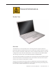
General Information Product View Overview The MacBook Pro (15-inch Early 2008) ushers in a fourth generation of Apple’s Intel-based professional notebook computers. Based on the new Intel Penryn chip, the architecture supports three clock speeds: 2.4GHz with a 3MB Shared L2 cache, 2.5GHz with a 6MB Shared L2 cache, and a configured-to-order 2.6GHz with a 6MB Shared L2 cache, the latter two with 512MB of VRAM. Two new larger hard drive sizes include 200GB/7200 RPM and 300GB/4200RPM.
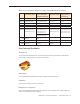
Main service and feature differences among 15-inch MacBook Pro models: MacBook Pro (15-inch Early 2008) MacBook Pro (15-inch 2.4/2.2GHz + Late 2007 2.6GHz CTO*) MacBook Pro MacBook Pro (15-inch Core 2 Duo) (original 15-inch & 15-inch Glossy) Intro Date February 26, 2008 June 5, 2007 / Nov 1, 2007 October 24, 2006 January 10, 2006 Micro- 2.5/2.4GHz Penryn, plus processor 2.6GHz CTO option 2.4/2.2GHz Core 2 Duo + *2.6GHz CTO (Late 2007) 2.33/2.16GHz Core 2 Duo 2.16/2.0/1.
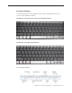
Keyboard Changes The new keyboard layout on the MacBook Pro (15-inch Early 2008) differentiates it from all previous 15-inch MacBook Pro models. MacBook Pro (15-inch original, Core 2 Duo and 2.4/2.
Using the Multi-Touch Trackpad Use the trackpad to move the pointer and to scroll, tap, double-tap, and drag. How far the pointer moves on screen is affected by how quickly you move your finger across the trackpad. To move the pointer a short distance, move your finger slowly across the trackpad; the faster you move your finger, the farther the pointer moves. To fine-tune the tracking speed and set other trackpad options, choose Apple > System Preferences, click Keyboard & Mouse, and then click Trackpad.
New trackpad gestures: pinching, rotating and swiping The following trackpad gestures work in certain applications, such as Preview or iPhoto. For more information, choose Help > Mac Help and search for “trackpad.” • Two-finger pinching lets you zoom in or out on PDFs, images, photos, and more. • Two-finger rotating lets you rotate photos, pages, and more. • Three-finger swiping lets you rapidly page through documents, move to the previous or next photo, and more.
Serial Number and Ethernet ID The Serial Number and Ethernet ID are located in the battery bay.
Display Takeapart The MacBook Pro (15-inch Early 2008) continues the whole display clamshell solution as the replacement part for any display failures or components contained within the clamshell. Electrostatic Discharge (ESD) Use a properly grounded ESD wrist strap and mat when working on the inside of the computer.
Service Source Take Apart MacBook Pro (15-inch Early 2008) © 2008 Apple Inc. All rights reserved.
Foot Tools This procedure requires the following tools: • Foot kit • Tweezers or needlenose pliers • Soft cloth Preliminary Step Before you begin, check the foot location that needs replacement and verify that the case plug is attached. Also verify that the case plug, and the case foot in the kit, match the pictures below. Plug Area on Bottom Case Matching Foot Action Missing case plug Not available for replacement Replace the bottom case, or send to Apple Repair Center.
Procedure Warning: The glue used in this procedure can bond instantly to skin. Do not touch the glue. In the event of contact, review the safety instructions at the end of this document. For additional information, refer to the glue manufacturer: Elmer’s Products, Inc. Columbus, OH. 43215-3799 www.krazyglue.com 1. Place the computer upside down on a clean, lint-free cloth or other nonabrasive surface. 2. Select a foot from the kit.
4. Warning: GLUE IS AN EYE AND SKIN IRRITANT. BONDS SKIN INSTANTLY. Do not touch the glue at any time. Before opening the glue, review the safety instructions at the end of this document. Important: The glue tube included in the kit is sealed until first use. Do not break the seal until you are ready to use the glue. To break the seal, hold the tube upright and away from you. Place the hollow nozzle cap on the tube and tighten it all the way down.
Battery Tools This procedure requires the following tools: • Clean non-marring work surface Preliminary Steps Warning: Always shut down the computer before opening it to avoid damaging its internal components or causing injury. After you shut down the computer, the internal components can be very hot. Let the computer cool down before continuing.
Procedure Warning: If the computer has been recently operating, allow it to cool down before performing this procedure. 1. Shut down the computer. 2. Disconnect the power cord and any other cables connected to the computer. 3. Place the computer face down. 4. Slide both battery latches away and lift the battery out of the battery bay.
Memory Tools This procedure requires the following tools: • #0 Phillips screwdriver (magnetized) • Clean non-marring work surface • ESD wrist strap and mat Preliminary Steps Before you begin, remove the following: • Battery Part Location MacBook Pro (15-inch Early 2008) Take Apart — Memory 20
Procedure Warning: If the computer has been recently operating, allow it to cool down before performing this procedure. 1. Place the computer face down. 2. Remove the three Phillips screws from the memory door. 3. Remove the door, as shown. Notes: • If only one memory card is installed, the factory installs it in the bottom memory slot. • Memory must be removed from the top slot before removing from the bottom slot.
4. To remove memory cards, carefully spread the two locking tabs for the slot (top or bottom) away from the card on both sides and allow the card to pop up slightly. 5. Pull the card straight back and out of the memory slot. Handle the memory card by the edges only, taking care not to touch the gold contacts.
Replacement Procedure Notes: • DDR memory cards do not fit in this slot, only DDR2 (different notch location). • If installing two cards, install the first card into the bottom slot before the top slot. • Align the notch in the memory card with the tooth in the slot before inserting. 1. To install memory cards, insert them at a 30-degree angle. ‘ Note: Insert the bottom card behind the locking tabs of the top slot. 2.
4. Verify that the card is fully seated by pushing firmly with your thumbs. 5. Check that the cards are secured by the brackets on both sides. 6. Install the memory door. 7. Replace the battery. 8. Use Apple System Profiler to verify that the memory is recognized. (Choose the menu bar Apple logo () > About This Mac, click More Info..., select the System Profile tab, open the Memory Overview.
Top Case Tools This procedure requires the following tools: • #0 Phillips screwdriver (magnetized) • Torx T6 screwdriver (magnetized) • Black stick (nylon probe 922-5065) or other non-conductive nylon or plastic flat-blade tool • Multi-compartment screw tray (such as a plastic ice cube tray) Preliminary Steps Before you begin, remove the following: • Battery • Memory Door Part Location MacBook Pro (15-inch Early 2008) Take Apart — Top Case 25
Procedure Notes: • If replacing the top case, once the top case is removed, use a razor knife to carefully lift and transfer the Serial Number and Ethernet ID labels to the replacement top case. • This procedure removes the top case and keyboard assembly. The keyboard is removable only after removing the top case. 1. Place the computer upside down on a soft, non-marring surface. 2. Remove the four Phillips and two Torx T6 screws shown. 3.
4. Remove the four Phillips screws from each side. 5. Remove the two Phillips screws from the back edge. .
6. Face the computer toward you with the display open slightly past 90-degrees. Using your fingernails or the tips of your fingers, grasp just beneath the top case in the upper right and left corners. Lift upward a few inches, then work your hands around the top case toward the front, slowly lifting and encouraging the clips and screw tabs to release. A snapping noise when the clips release is normal.
7. Along the front, start at the left and slowly encourage the snaps and screw tabs (shown in graphic below) to release as you move right. A snapping noise as the snaps release is normal. Again, take care to preserve the cosmetic integrity of the plastic beading around the edges by pulling up with your fingernails first. If a black stick is necessary to release the snaps, avoid too much rotation along the edges to keep from denting the soft plastic.
Important: To avoid bending screw tabs along the back edge of the top case, lift the top case slightly so that it does NOT touch the bottom case, then rotate the front of the case up and back until you can disconnect the keyboard flex cable from the logic board.
Replacement Procedure Note: If replacing the top case, remove the keyboard and transfer to the replacement top case. (See keyboard section in next chapter for replacement instructions.) Note: Unique identifiers for this top case include three circular black mylar dots over the keyboard screws. 1. Visually check to verify that all cables are connected and routed correctly with nothing raised up or incorrectly placed over a component. 2.
5. Check that the perimeter screw tabs and ribs are not bent. Note: The metal can quickly fatigue and break off. Be extremely careful to gently straighten tabs, if needed. 6. Verify that the plastic spacer is on the front screw tab, shown. 7. If the back screw tabs are bent out, straighten by pressing the edge of the case on a hard flat surface and rolling to vertical.
8. Any screw tabs that are not straight will not fit or accept screws correctly. 9. Use your finger and a black stick to carefully straighten bent screw tabs. 10. Connect the flex cable from the top case to the logic board.
11. Lift the top case off the bottom case slightly and rotate it down (verify that the keyboard cable stays connected and is folding properly) and align the corners. 12. Carefully pull or push tabs slightly, if needed. Note: Guarded, controlled pushing with your thumb may be helpful to gently finesse the tabs into place. 13. Verify that the screw tabs in back are straight and guide them inside the bottom case. Work your way around guiding the screw tabs into the bottom case along both sides.
14. The two front screw tabs (shown below) may need to be guided with a black stick through the battery bay. 15. Squeeze at the five snap locations along the front edge of the top case (to the right of the screw tabs) to verify that the they are seated. You should hear five audible snaps when pressing down the front edge of the top case at these locations. The top case should lay flat along all sides and top; if not, make sure cables and components are not interfering. 16.
18. Install the bottom Phillips screws and the two Torx T6 screws near the memory chips. 19. Install the two Phillips screws in the battery bay. Important: For the screw shown, push in the display latch button while installing the screw.
20. Check that the edges of the top case sit flush with the bottom case around the entire perimeter of the computer. If there are noticeable gaps, reinstall the top case taking extra care to secure top case top bottom when replacing the perimeter screws. 21. Install the memory door and replace the battery. Quick Test • • • Powering on, check the keyboard and trackpad function. Operate the computer in a darkened room to check for keyboard backlight function.
Keyboard Tools This procedure requires the following tools: • #0 Phillips screwdriver (magnetized) • Black stick (nylon probe 922-5065) or other non-conductive nylon or plastic flat-blade tool Preliminary Steps Before you begin, remove the following: • Battery • Top Case Part Location MacBook Pro (15-inch Early 2008) Take Apart — Keyboard 38
Procedure Important Notes: • The MacBook Pro (15-inch Early 2008) keyboard is not interchangeable with any previous models, including the original 15-inch MacBook Pro, Core 2 Duo and 2.4/2.2GHz. If replacing the keyboard, verify that the correct replacement keyboard and/or top case is ordered. • The keyboard comes as a multi-layered assembly and includes backlighting. Do not disassemble the keyboard itself. Dust, fingerprints, or misalignment can cause improper function and damage to the assembly. 1.
3. Rotate the top case to have the cable connectors facing you for better access. Carefully lift the perimeter of the cover nearest the cable connectors to release the adhesive. If necessary, use a razor knife to lift up the edge enough to slide in a black stick (see inset below). 4. Gently lift and hold up that half of the cover with the black stick to provide adequate access to the connectors. Important: Keep the cover and its underlying adhesive clean and intact. 5.
6. Note the positioning, then peel off the insulator film covering the back of the keyboard well, including mylar screw covers. Reserve the film and keep it clean for reinstallation. Important: Use care at the notches and narrow parts to avoid ripping or tearing the film.
7. Use needlenose pliers to gently straighten the six bend-tabs located along the bottom edge, as shown. These tabs lock down and stiffen the top edge of the keyboard. Important: The bend-tabs are delicate. Bend them carefully to avoid damage. Avoid over-bending. 8. Remove the twelve Phillips #00 keyboard screws. Be sure to sandwich keyboard to top case when removing the final screws.
9. To prevent the keyboard from falling out, support it with your hand, and raise the top case up vertically. Note: This keyboard has no side tabs like previous models. 10. If you lean the top case toward you top first, the keyboard may simply fall into your hands.
11. Note the six insert-tabs along the bottom edge of the keyboard that tuck into the lower edge of the keyboard well. 12. Lift the keyboard up and away from the top case to release the tabs along the bottom edge and carefully thread out the flex cables. Important: During this procedure, do not allow the tabs or metal edge of the keyboard to scrape along the cosmetic surface of the top case; otherwise damage can result.
Replacement Procedure When replacing the keyboard, here are some key points to keep in mind: • Prevention of scratches to the cosmetics of the top case • All tabs are properly seated • Keyboard lays flat • Bend-tabs are not damaged • Screw holes align • Cables are not caught • Cable connectors are not damaged and cables are secure • Kapton tape is applied as before • Insulator film is correctly installed 1.
3. Verify that the small backlight cable routes through the slot, as shown. 4. Lower the keyboard into the well and seat all six tabs along the bottom, so that the keyboard sits flat and straight.
5. Verify that the bend-tabs are not caught. 6. Pull on the flex cables to verify that they are not bent or caught under the keyboard, and that they extend to their connectors. 7. Verify that the screw holes align with the screw bosses, and, holding the keyboard in place with your other hand, work outward from the middle to install all twelve keyboard screws. 8. Bend the six bend-tabs over the metal of the top case to secure the edge of the keyboard. Important: The bend-tabs are delicate.
9. Insert the two flex cables into their connectors and secure. Verify that the cables are fully inserted and secured straight. Kapton tape will be applied to the small connector later. 10. Reinstall the protective cover over the area shown. Carefully burnish down the edges to secure.
11. Replace the insulator film and mylar screw covers in the same locations from which they were removed. Ensure the holes in the film match up correctly with the screw bosses. Avoid wrinkles and bulges. If installing a replacement top case, use the new film if supplied. Important: The film must be installed in the same location to protect against contact and electrical shorting in certain areas as well as to allow connection with the EMI spring on the logic board. 12.
AirPort Extreme Card Tools This procedure requires the following tools: • Torx T6 screwdriver (magnetized) • Black stick (nylon probe 922-5065) or other non-conductive nylon or plastic flat-blade tool • Kapton tape (922-1731) (0.
Procedure 1. Disconnect the two antenna connectors, lifting straight up. 2. Remove the Torx T6 screw and bracket, and peel up any kapton tape holding down the Airport card, if present. Note the kapton tape may wrap around speaker cables on the right. 3. Once the card is freed from the bracket and tape, it should rise up slightly. Pull the card straight out of its socket at the angle shown below.
4. Verify that the antenna cables route flat in the channel and underneath the two brackets on the left speaker. Secure with Kapton tape, if necessary. 5. Connect each antenna cable to its respective terminal. Note that the color of each antenna cable corresponds with a matching color key located above the terminals. 6. Verify that the ambient light sensor flex cable is connected properly. 7. Reassemble the computer.
Bluetooth Card Tools This procedure requires the following tools: • #0 Phillips screwdriver (magnetized) • Black stick (nylon probe 922-5065) or other non-conductive nylon or plastic flat-blade tool • Kapton tape (922-1731) (0.
Procedure 1. Disconnect the Bluetooth antenna connector from the Bluetooth card, pulling straight up. 2. Remove one Phillips screw from the lower right corner of the Bluetooth card. 3. Remove the plastic protective cover by sliding it gently off the card, taking care to preserve its integrity for reuse. Set the cover aside to use with the replacement Bluetooth card. 4. Holding the Bluetooth card by its edges, use a black stick to disconnect the cable connector from the card as shown below.
Replacing the Bluetooth cable 1. To remove or replace the Bluetooth cable, gently pry up adhesive using a black stick. 2. Disconnect the other end of the cable as shown. Quick Check: Use Apple System Profiler to see if Bluetooth HCI appears under the USB Bus tab in the USB device section.
Bluetooth Antenna Tools This procedure requires the following tools: • #0 Phillips screwdriver (magnetized) • Black stick (nylon probe 922-5065) or other non-conductive nylon or plastic flat-blade tool • Razor knife • Kapton tape (922-1731) (0.
Procedure 1. Disconnect the Bluetooth antenna connector from the Bluetooth card, pulling straight up. 2. Remove two captured Phillips #0 screws from black plastic antenna shield which are accessible via screwdriver through two visible holes in the foam cover.
3. Pry shield up from top case using a black stick, taking care to preserve adhesive underneath. 4. Use a black stick to remove the antenna, prying it up to release the adhesive. Replacement Note: If you remove the Bluetooth board during antenna replacement, reapply its protective cover and secure with Kapton tape if necessary before reinstalling on the top case.
Infrared Board Tools This procedure requires the following tools: • Torx T6 screwdriver (magnetized) • Black stick (nylon probe 922-5065) or other non-conductive nylon or plastic flat-blade tool Preliminary Steps Before you begin, remove the following: • Battery • Top Case Part Location MacBook Pro (15-inch Early 2008) Take Apart — Infrared Board 59
Procedure 1. Note the path and routing of the sleep light cable which sits above the IR cable (twisted red and black wire partially wrapped in Kapton tape). Gently lift the cable up and aside without disturbing either the sleep light connector or the sleep light board soldered to the frame. 2. Disconnect the IR cable connector from the flex cable on the hard drive. 3. Remove the Torx T6 screw and bracket above the IR board.
4. Using a black stick, lift out the infrared board. Lifting from both ends may also be helpful. Important: Lift on the board only. Do NOT lift the infrared lens or sensor piece. It is secured to the main board with two wires and will bend out of alignment. Note: Be sure to slip the cable out from under the small peg in the frame. Replacement Procedure 1. To install, insert the board all the way into the channel, then gently maneuver the board until the infrared lens aligns with the window.
2. Connect the IR cable connector to the flex cable on the hard drive. 3. Reinstall the bracket and Torx T6 screw above the IR board. 4. Route the IR and sleep light cables as shown below, making sure to tuck both cables under the peg on the frame. Quick Test • Open Apple System Profiler and check to see that IR Receiver appears under the USB Bus tab in the USB device section.
Hard Drive Tools This procedure requires the following tools: • #0 Phillips screwdriver (magnetized) • Torx T6 screwdriver (magnetized) • Black stick (nylon probe 922-5065) or other non-conductive nylon or plastic flat-blade tool • Kapton tape (922-1731) (0.
Procedure NOTE: Some hard drives may have a metal disk attached to them for vibration stabilization (as shown below) while other models may not. 1. Carefully pry up the flex cable from the hard drive. 2. Lift up cabling to gain some clearance.
3. Remove the two Phillips #0 screws from the drive bracket. 4. Remove the hard drive bracket.
5. Using a black stick, tilt the hard drive up slightly on the right side; then work the hard drive out of its grommet wells on the left side and lift up just enough to access the flex connector. 6. If there is Kapton tape securing the flex connector, remove it very carefully to ensure that you don’t damage the label. A damaged label voids the warranty of the hard drive. (Note that most hard drives may not have a vibration dampening disc like the one below.
7. 8. Kapton tape may wrap all the way around the flex connector to the back side of the hard drive. If so, hold the hard drive by its sides to turn it over and release the Kapton tape. 9. Gently pry the flex connector from the hard drive.
Replacement Procedure 1. Transfer the rubber grommets and screws. Replace any Kapton tape around flex cable. NOTE: Some hard drives may have a metal disk attached to them for vibration stabilization. Do not transfer this disk if the replacement drive comes without one. If a replacement hard drive needs this metal disk, it will come preattached.
2. Tilting the hard drive as you insert it, tuck the screws on the left side of the hard drive into the grommets in the bottom case. 3. After lowering drive into place, replace bracket and screws.
4. Make sure the flex cable is re-adhered to its spot under the infrared connector. Note: Notice there may be a warning label that says Do Not Cover This Hole directly under the hard drive/IR flex cable. Not to worry. Because the vent hole is recessed, the upper portion of the flex cable end can cover the hole without actually blocking it.
However, be sure that the lower part of the flex cable (with the Infrared cable connector) is the portion that actually adheres to the hard drive. The sticky area should not cover the hole. In the shot below you can see where the adhesive residue is located.
Optical Drive Tools This procedure requires the following tools: • #0 Phillips screwdriver (magnetized) • Torx T6 screwdriver (magnetized) • Black stick (nylon probe 922-5065) or other non-conductive nylon or plastic flat-blade tool Preliminary Steps Before you begin, remove the following: • Battery • Top Case Part Location MacBook Pro (15-inch Early 2008) Take Apart — Optical Drive 72
Procedure 1. Disconnect the flex connector, removing any Kapton tape securing it. 2. Remove two Phillips #0 screws on the main logic board (the one on the right with a blue washer) and the two smaller Phillips #00 screws near the frame. Lift out the drive by edges. 3. Transfer three brackets, including one EMI gasket, and flex cable to the replacement drive.* * Important: See the subsequent section about handling slot-load optical drives.
MacBook Pro (15-inch Early 2008) Take Apart — Optical Drive 74
Handling Slot-Load Optical Drives Follow the instructions in this section carefully. This procedure shows how to handle slot-load optical drives when they are outside the computer. • Observe ESD (electrostatic discharge) guidelines when handling optical drives. • Handle the drive only by the sides and back edge.
• Do not touch the front of the drive. • Do not press on the drive or lift it by the top and bottom cover. • Do not handle the drive by the gull wing edge only.
• When storing optical drives, use approved packaging boxes. Never stack loose drives. • When returning a defective optical drive, use the original packaging and an antistatic bag. Pack only one drive per box.
Replacement Procedure 1. Verify that the EMI gasket is installed on the bottom case in the back of the drive bay. Important: The optical drive must be installed so that it does not sit on top of the gasket. Insert the drive toward the logic board so that the gasket is pushed behind the drive.
Removing a Stuck Disc from an Optical Drive Important: This procedure applies only to 9.5-mm and 12.7-mm slot-load optical drives. 1. Remove the four identical screws that hold the top cover to the drive. Note: You may need to remove a paper label to access one of the screws, as shown below. 2. Slide the top cover ~2 mm toward the back of the drive. Lift up the top cover to remove it.
3. Check the placement of the disc. It is either clamped to the turntable at the center of the disc, or it is wedged under one or more posts at the outer edge of the disc. 4. Holding the edge of the disc, press on the center clamp or hold the posts steady as you remove the disc from the drive. Important: Do not touch any key components located near the disc. 5. Replace the top cover on the drive so that the small hooks on the top cover fit into the slots on the bottom cover.
Backup Battery Tools This procedure requires the following tools: • Black stick (nylon probe 922-5065) or other non-conductive nylon or plastic flat-blade tool Preliminary Steps Before you begin, remove the following: • Battery • Top Case • Optical Drive Part Location MacBook Pro (15-inch Early 2008) Take Apart — Backup Battery 81
Procedure 1. First note the cable routing. There is a notch in the logic board that allows you to tuck the cable underneath it and next to the frame during replacement. 2. Disconnect the JST cable connector from the logic board. (See next section for JST details.) 3. To remove the battery, use a black stick to pry it away from the bottom case, taking care to preserve the adhesive backing for reuse if necessary. 4.
JST Connectors 1. To disconnect a JST connector, sandwich the connector firmly between a finger on top and a black stick under the cabling next to the connector, then lift (as in the animation below). 1. 2. To re-seat or reconnect a JST connector, use a black stick or your finger to snap it into place, making sure the connector sits perfectly flat and flush with the sides of the connector well.
Note: Given a very keen eye, one way to distinguish the right side up of a JST connector is by looking for the word ‘push’ on the top side of the connector, as shown below.
Left Ambient Light Sensor Tools This procedure requires the following tools: • #0 Phillips screwdriver (magnetized) • Torx T6 screwdriver (magnetized) • Black stick (nylon probe 922-5065) or other non-conductive nylon or plastic flat-blade tool Preliminary Steps Before you begin, remove the following: • Battery • Top Case Part Location MacBook Pro (15-inch Early 2008) Take Apart — Ambient Light Sensors 85
Procedure The left ambient light sensor is on a separate circuit board mounted with adhesive to the left speaker. Its dust cover is secured with one screw. The right ambient light sensor is built into the main logic board. Its dust cover is adhered to the underside of the top case (see Right ALS Cover). To remove the left ambient light sensor board: 1. Remove the Phillips screw and dust cover. 2. Disconnect the JST connector on the logic board to the right of the fan.
3. Peel the ALS cable away from the fan, taking care to preserve the adhesive for future use. 4. Pry up the sensor board to release its adhesive and remove it from the speaker. Reinstallation Note: When reinstalling the dust cover, carefully blow off any dust and gently clean the lens with a soft, lint-free cloth if necessary.
Right ALS Dust Cover Tools This procedure requires the following tools: • Black stick (nylon probe 922-5065) or other non-conductive nylon or plastic flat-blade tool Preliminary Steps Before you begin, remove the following: • Battery • Top Case Part Location MacBook Pro (15-inch Early 2008) Take Apart — Ambient Light Sensors 88
Procedure The right ambient light sensor is part of the logic board. Its dust cover is now mounted on the underside of the top case. The left sensor is on a circuit board mounted to the left speaker (see Left Ambient Light Sensor). To replace the right sensor’s dust cover: 1. Peel away dust cover from the top case and transfer as necessary. Reinstallation Note: When reinstalling the dust cover, carefully blow off any dust and gently clean the lens with a soft, lint-free cloth if necessary.
Fans Tools This procedure requires the following tools: • Torx T6 screwdriver (magnetized) • Black stick (nylon probe 922-5065) or other non-conductive nylon or plastic flat-blade tool • Razor knife • Kapton tape (922-1731) (0.
To remove the left fan: 1. Remove three Torx T6 screws. Note the black screw in the right lower corner. . 2. Disconnect the three cable connectors, the lower two being JST connectors. 3. The top connector must be guided out laterally to the left with a black stick as shown below.
4. Carefully peel the flex cable off the fan cover. 5. Lift the fan up and to the left, carefully peeling the tape away from the heatsink, preserving it for reuse. Work the fan’s upper left screw bracket out from under the left speaker bracket. Note: Avoid damage to the gold spring on the logic board to the right of the fan (see inset).
To remove the right fan: 1. Remove the three Torx T6 screws shown below. 2. Remove any Kapton tape, if necessary, and disconnect the fan cable JST connector shown below by holding the cable just next to the connector and gently tugging straight up.
3. Lift the fan up and to the right, carefully peeling the tape away from the heatsink, preserving the tape for reuse during reinstallation. Replacement Notes 1. After replacing either fan, position the tape directly over the heatsink fins in the fan’s previous position and press firmly along the length of the tape to seal it to the heatsink.
2. If needed, apply Kapton tape to secure the iSight camera and inverter cable bundle (top) and the ambient light sensor cable bundle (bottom) to the left fan.
Logic Board Tools This procedure requires the following tools: • #0 Phillips screwdriver (magnetized) • Torx T6 screwdriver (magnetized) • Black stick (nylon probe 922-5065) or other non-conductive nylon or plastic flat-blade tool • Multi-compartment screw tray (such as a plastic ice cube tray) • Kapton tape (922-1731) (0.
Part Location Procedure 1. Remove the small square EMI gasket adhered to the LVDS ground screw (upper right). 2. Disconnect the cables shown below. Clockwise from bottom left: left I/O board connector, hard drive connector, three thermal sensor connectors, and the LVDS cable connector.
3. Remove the Torx T6 screw that secures the ground clip for the LVDS cable. 4. Remove eight silver Torx T6 screws, one black Torx T6 (upper right) and one black Phillips screw (just to the right of the memory slots). 5. Tape the thermal sensor cable to the display assembly to avoid trapping it under the logic board and forgetting it during reassembly.
6. Warning: Do NOT allow the logic board to flex at any time. Flexing the board can crack solder joints to components. Give special attention at the narrow neck of the fan cutout. 7. From the left side of the board, slowly begin to lift the board, avoiding any flexing, until the thermal material on the three chips underneath releases. Do not lift the board further. Note: The thermal material should easily release. If not, verify that all screws and connectors have been removed. 8.
Replacement Procedure 1. Verify that the EMI gaskets are in place along the port openings on the bottom case. 2. If the existing logic board was removed to facilitate another procedure and will be reinstalled, the old thermal material must be removed from both the logic board and the heatsink, and new thermal material will be applied. See step 5 for reapplication instructions. • Use a black stick and alcohol wipes to clean the old thermal grease from the three chips.
3. Install EMI gaskets and tape on the ports from the gasket kit (076-1261). \ • Transfer the logic board sleeves (922-7538) to the replacement board, if needed. • Transfer the cosmetic shield, if needed.
4. Use a black stick to remove as much old thermal grease as possible from the heatsink. 5. Use an alcohol wipe to clean the mating surfaces. 6. Note the contents of the syringe of the replacement thermal grease. Important: One syringe (922-7144) contains 0.3 to 0.35 cubic centimeters (cc) of thermal grease. That is enough for 0.1 to 0.12 cc of grease per chip for up to three chips. Use one-third of the syringe contents per chip.
7. Put a 0.1 - 0.12cc dab of thermal grease in the center of each chip mating surface, as shown. 8. When replacing the logic board: • Verify that the two plastic screw guides are installed on the top of the board. • Guide the logic board’s port side into the port openings on the bottom case. • Carefully lower the board over the right speaker, being aware of its exact placement to avoid breakage along the delicate area where it narrows to the left side of the speaker.
9. Install the logic board screws in the order shown below. 10. Verify that the ExpressCard cage flex connector is seated properly. 11. Reassemble and test all ports, components and functions of the computer. Note: After installing new thermal material, if you must briefly re-separate the logic board from the heatsink, it is acceptable to retain the same new thermal material, as long as the material is not handled excessively.
Battery Cable Assembly Tools This procedure requires the following tools: • Torx T6 screwdriver (magnetized) • Black stick (nylon probe 922-5065) or other non-conductive nylon or plastic flat-blade tool Preliminary Steps Before you begin, remove the following: • Battery • Top Case • AirPort Extreme Card • Speakers • Fans • Optical Drive • Logic Board Part Location MacBook Pro (15-inch Early 2008) Take Apart — Battery Cable Assembly 105
Procedure Take note of cable routing before removal and replacement. 1. Remove the two 8.5mm Torx T6 shoulder screws.
2. Disconnect the connector on the left I/O board. 3. Replacement Note: Route cable as shown, and secure with Kapton tape in the channel.
Heatsink Tools This procedure requires the following tools: • Black stick (nylon probe 922-5065) or other non-conductive nylon or plastic flat-blade tool • Thermal grease (922-7144) Preliminary Steps Before you begin, remove the following: • Battery • Top Case • Fans • Optical Drive • Logic Board Part Location MacBook Pro (15-inch Early 2008) Take Apart — Heatsink 108
Procedure 1. Once the parts are removed in the preliminary steps, lift out the heatsink. 2. When installing the heatsink, make sure that it fits over the pins, shown below, and lays flat. 3. Make sure to install new thermal grease as outlined in the logic board chapter.
Thermal Sensors Tools This procedure requires the following tools: • Black stick (nylon probe 922-5065) or other non-conductive nylon or plastic flat-blade tool • Razor knife • Kapton tape (922-1731) (0.
Procedure There are three thermal sensors, each requiring precise placement. Two sensors are attached to the bottom case near each fan and one to the heatsink. 1. For each sensor, peel back any Kapton tape, and before removing the board, mark the outline of its position with a permanent fine-point felt-tip marker. Note: Be sure to note the orientation of the ‘tail’ of each thermal sensor before removal.
1. Pry up the sensor board with a razor knife. 2. Install the replacement sensors in the exact same location. (Note: Be sure to reinstall each thermal sensor in the proper orientation, with the ‘tail’ facing in the correct direction.) 3. Replace any Kapton tape.
Speakers The right and left speakers are one assembly. Tools This procedure requires the following tools: • #0 Phillips screwdriver (magnetized) • Torx T6 screwdriver (magnetized) • Black stick (nylon probe 922-5065) or other non-conductive nylon or plastic flat-blade tool • Kapton tape (922-1731) (0.
Procedure Note: Some photo details below may differ slightly from the model or state of repair of the MacBook Pro you are repairing; however, the procedure itself remains consistent for this model. To remove the left speaker: 1. Remove the Torx T6 screw from the upper left of the fan. Carefully note the cable routing. 2. If present, disconnect the hard drive flex connector and lift the flex cable from the ExpressCard cage to gain access to the speaker cables and connector. 3.
To remove the right speaker: 1. Remove all components listed on the first page of this chapter. (Note that the display need not be removed to remove the speakers.) 2. Gently begin to pull the first few inches of speaker wire leading from the left speaker to the right away from the adhesive on the left side of the bottom case. 3. Use a black stick to carefully pry the wire out from under the brackets securing the wire to the rear of the bottom case.
4. Remove the Torx T6 screw and lift the speaker away from bottom case. Note: A light adhesive may be securing the speaker in place. Use a black stick to gently pry the speaker away from the bottom case.
Replacement note: While tucking speaker wire under the bracket in the back of the bottom case, use a black stick to wedge the bracket slightly upward while sliding the wire underneath to avoid cutting the wire’s insulation. Make sure the speaker wire is pushed all the way under each bracket in the rear of the bottom case to keep it from interfering with the reinstallation of the heatsink.
Left I/O Board Tools This procedure requires the following tools: • Torx T6 screwdriver (magnetized) • 4 mm socket wrench • Black stick (nylon probe 922-5065) or other non-conductive nylon or plastic flat-blade tool Preliminary Steps Before you begin, remove the following: • Battery • Top Case • AirPort Extreme Card • Left Ambient Light Sensor (just the JST cable on the logic board side) • Left Speaker Part Location MacBook Pro (15-inch Early 2008) Take Apart — Left I/O Board 118
Procedure 1. Disconnect the battery cable. Note: The ExpressCard cage is attached to the left I/O board. 2. Remove the four 4.2mm Torx T6 screws and single 4mm hex standoff.
3. Lift the board assembly from the right side and slide away from the port openings. 4. Disconnect the flex cable. Note: The new left I/O board for the MacBook Pro (Early 2008) now has EMI mylar film on the bottom of the board. Leave the film in place.
5. Remove the four screws. 6. Lift off the card cage.
7. Replacement Note: Transfer the three EMI gaskets from the old card. Important: Also transfer any other gaskets present on the ExpressCard cage, whether replacing the cage or the left I/O board. Replacement Note: Make sure the four gaskets on the bottom case that make contact with the four screws on the underside of the ExpressCard cage are intact.
Replacement Note: When the board is in place and the ports are seated, hold the power adapter port tightly against the port opening while installing screws. Replacement Note: After securing the board, exercise the ExpressCard slot door to verify proper clearance.
ExpressCard Cage Tools This procedure requires the following tools: • #0 Phillips screwdriver (magnetized) Preliminary Steps Before you begin, remove the following: • Battery • Top Case • AirPort Extreme Card • Left Ambient Light Sensor (just the JST cable on the logic board side) • Left Speaker • Left I/O Board Part Location Procedure See the Left I/O Board chapter for removal of the ExpressCard cage.
Bottom Case Tools This procedure requires no tools.
Part Location Procedure After the parts are removed in the preliminary steps, disconnect and remove the hard drive/ infrared flex cable from the sleep LED cable. What’s left is the bottom case. Note: When replacing the bottom case, make sure to transfer any corresponding gaskets that are not included in the replacement part.
Display Assembly Tools This procedure requires the following tools: • Torx T6 screwdriver (magnetized) • Black stick (nylon probe 922-5065) or other non-conductive nylon or plastic flat-blade tool Preliminary Steps Before you begin, remove the following: • Battery • Top Case Part Location MacBook Pro (15-inch Early 2008) Take Apart — Display Assembly 127
Procedure 1. Disconnect three antenna connectors. Lift straight up. Peel up any Kapton tape to free. 2. Disconnect the DC-to-DC (backlight) cable connector in the left corner. Remove the screw securing the iSight camera cable and disconnect the cable connector to the right of the fan.
3. Disconnect the LVDS cable. 4. Move the display to a 90-degree angle and remove the four clutch screws. Note: The 9.5mm shoulder screws are located toward the inside of the machine. Important: Support the display from falling over before removing the last screw.
5. Lift the display straight up and off of the computer without catching wires.
Replacement Procedure 1. Install the replacement display panel assembly. 2. Make sure to capture the LVDS cable grounding loop with the back screw. 3. Verify that the LVDS cable is secure and lays flat. 4. Reassemble and test the computer. Quick Test • • • • • Test that the display panel functions properly. Use Apple System Profiler to check that the AirPort Extreme card is recognized, and test that AirPort Extreme is working. Check the camera function.
Service Source Adjustments MacBook Pro (15-inch Early 2008) © 2007 Apple Inc. All rights reserved.
Latch Adjustment Overview To secure the display to the top case, the MacBook Pro uses a latch assembly that consists of two parts—a latch mechanism under the top case (actually attached to the bottom case frame) and two swinging latch hooks inside the display assembly clamshell. As the unit is closed, magnets inside the latch mechanism pull the metal latch hooks down into the bottom case, and an overhang on the latch mechanism clasps the hooks to the frame.
Procedure Note: The latch mechanism under the top case of the computer has a small amount of right and left play (less than 1 mm), and can shift during normal operation. The following procedures will test the latching function with the latch mechanism at its maximum right and left positions, and the latch hooks will be very slightly adjusted, as necessary. Important: The latch hook metal can become brittle and break if it is bent too much, especially if it is over-bent and bent back.
3. Perform the testing procedures in step 1 of the Preliminary Steps, above. 4. If the latch functions properly, skip to step 6; otherwise, if either or both latch hooks require an adjustment, refer to the following steps. 5. If the latch mechanism does not function properly, adjust the latch hook(s) as follows: Open the display to a 90-degree angle and use a magnet to draw the latch hook out. Tightly grasp it between your thumb and forefinger as close to the display as possible, as shown.
Service Source Troubleshooting MacBook Pro (15-inch Early 2008) © 2007 Apple Inc. All rights reserved.
General Information Wire and Flex Cables Because of its thin enclosure design and dispersed circuit board, the MacBook Pro utilizes a multitude of flex cables and wire cable harnesses. Many of these cables carry multiple signals. Here is a list of the cables and the signals that run across them. If you notice a group of functions not working, it is likely that the cable is not properly inserted or the connector is damaged.
Cable or Flex Cable Signal(s) Running Through It Right fan cable Power/control for right fan DC-to-DC cable (to left I/O board) Display backlight control iSight video signal cable Video power and signal from iSight camera LVDS cable Video data Backlight power and control cable Display brightness (CCFL or LED) Thermal sensors (bottom case (2), heatsink) Internal temperature data Microphone and Camera wires The following photo shows the microphone wires located on the left speaker, and the camer
4. Press the Return key or click the right arrow button. 5. When the Apple Hardware Test main screen appears (after about 45 seconds), follow the onscreen instructions. 6. If Apple Hardware Test detects an issue, it displays an error code. Make a note of the error code before pursuing support options. If Apple Hardware Test doesn’t detect a hardware issue, the issue may be software related. If this method is not successful, use AHT from the MacBook Pro OS X Install DVD.. To use AHT from the DVD: 1.
12. Click the Restore button to start the installation. 13. In Disk Utility, select the volume on the USB hard drive named ASD EFI 3S121. 14. Click on the Restore tab 15. For Source, select the ASD EFI disk image by either dragging the icon for the disk image to the Source window, or selecting it by clicking on the Image button. Note: Image ASD EFI 3S1121.dmg should be unmounted before restoring it to the hard drive. 16.
Resetting the Power Manager (SMC) Power management is handled by a chip called the SMC (System Management Controller). To reset the SMC: 1. If the computer is on, turn it off. 2. Disconnect the power adapter and remove the main battery. 3. Hold the power button down for five seconds, then release. 4. Install the main battery and connect the power adapter. 5. Press the power button to restart the computer.
the Boot ROM, and SMC Updates update the System Management Controller firmware. The SMC manages fans and other environmental parameters that are independent of the Boot ROM. Firmware symptoms can be easily mistaken for hardware issues (e.g. overheating issues, fan noise issues, etc.). Always check both EFI and SMC firmware versions and update if necessary before replacing any hardware components in the MacBook Pro.
Customer forgot password If the customer forgot the password for the computer: 1. Insert the MacBook Pro Mac OS X Install Disc 1 DVD. 2. Restart the computer while holding down the C key on the keyboard. 3. When the installer appears, chose Reset Password under the Installer Utilities menu. 4. Follow the on-screen instructions. Safe Mode Safe Boot is a special diagnostic way to start Mac OS X when troubleshooting. Safe Mode is the state Mac OS X is in after a Safe Boot.
Troubleshooting Steps You should perform the first few steps of troubleshooting regardless of whether there is a repairable problem or damage. Gather Information Gather the normal information about the problem. (If you are not familiar with the normal information to gather, or any of the other steps, see General Troubleshooting Theory.) Verify the Problem Verify that the symptom exists as the customer reports it.
Research If you have not located the trouble following the steps thus far, try researching the symptoms. Research resources include: • Symptom Charts section of this manual • GSX gsx.apple.com Enter serial number and click Coverage Check • Service Source service.info.apple.com Check Quick Links and/or Technical Resources Check options under appropriate Product Service pop-up menu • Product support page service.info.apple.
Inform the User Include in the case notes all that you have done. The customer may like a copy of any diagnostic reports. Important: For any unit you send on to a repair center, include the CompTIA code, symptoms, steps to reproduce, and troubleshooting steps you have completed thus far in the Service Instructions section of GCRM and/or GSX. (Service Instructions are also known as FAI notes.
Hardware Symptoms How to Use the Symptom Charts The Symptom Charts included in this chapter will help you diagnose specific symptoms related to the product. The steps to solve a symptom are listed sequentially. You might not need to perform every step before the symptom is resolved. Start with the first step, and then test for the symptom. If the symptom persists, replace any modules you removed, go to the next step, and test again. Continue down the list until the symptom is resolved.
1. Remove any connected peripherals and eject any ExpressCard. 2. Check that the battery has enough charge to start the computer by pressing the button next to the LEDs on the battery (on the bottom of the machine). At least one LED must light solid (not flashing). Make sure the battery is fully seated. 3. Connect a known-good Apple 85W Portable Power Adapter and power cord or plug to a knowngood power outlet.
Power-On Self Test (POST) Error Codes The computer automatically performs a power-on self test when it is turned on after being fully shut down (not a restart). This section describes what to do if you hear beeps during startup. When this occurs, the sleep LED will stay on, occasionally flashing. MacBook Pro relies on a combination of tones and blinking sleep LEDs to display power-on self test (POST) error codes.
Flashing question mark appears on the screen Note: This system will only boot with the version of Mac OS X system that shipped with this computer or later. It does not support booting into Mac OS 9. 1. Start up from the MacBook Pro Mac OS X Install Disc 1 DVD that came with the computer (hold down the “C” key during restart). 2. When the Installer opens, select Disk Utility from the Installer menu under Utilities. 3.
System shuts down intermittently 1. Disconnect all external peripherals and eject any ExpressCard. 2. Consult system.log for possible shutdown error codes using Console (in Utilities folder). Shutdown Code Potential Indication, Issue and/or Fix 3 Normal behavior... power button was pressed for more than four seconds to force shutdown. -5 Normal behavior... regular shutdown -60 Try charging battery. -70 Replace top case.
Ts0P Top case Th1H Thermal sensor on heatsink TG0H Bottom case thermal sensor near right fan Th2H Bottom case thermal sensor near left fan 11. Verify that the left I/O board cable is securely connected and shows no signs of wear. 12. Try known-good left I/O board. 13.
bad DIMMs are replaced with known-good modules. 7. Replace the logic board. AirPort Extreme Note: The AirPort Extreme card is separate from the Bluetooth module, the AirPort antenna is in the clutch barrel behind the gray plastic window, and the Bluetooth module and antenna are mounted underneath the top case. AirPort Extreme card is not recognized 1.
9. Check AirPort Extreme antenna wires coming from clutch barrel for nicked insulator or crimped wire. If damaged, replace the display assembly. 10. Check the left I/O flex cable for proper seating on both the left I/O board and logic board. 11. Replace the left I/O board. 12. Replace the main logic board.
3. Replace the battery. For more information and visual examples, consult Knowledge Base article 303922: MacBook, MacBook Pro (15-inch), or MacBook Pro (17-inch) with swollen battery. The battery won’t charge 1. Remove any externally connected peripherals. 2. Try a known-good power outlet. 3. Connect a known-good MagSafe 85W power adapter with power cord or plug. If the DC plug is properly inserted, the LED should light up. If not, troubleshoot the MagSafe connection and power adapter.
2. Reset the SMC (power manager) as described in “Resetting the System Management Controller (SMC)” under “Troubleshooting Tips and Tricks” in the previous section. 3. The battery needs calibration, or it is nearing the end of its useful life. • Calibration should be done when you first use the battery, and every few months after. It allows the battery to properly calculate how much power is left in the battery. • The battery is a consumable part.
Bluetooth Bluetooth system preference pane does not show up under hardware section of System Preferences 1. Check for software/firmware updates on the web. 2. Check the Bluetooth card flex cable underneath the top case. Make sure the cable is not damaged and is fully seated. 3. Check the Bluetooth flex connection to the trackpad flex. 4. Check the top case flex connection to the main logic board. 5. Replace the Bluetooth card. 6. Replace the top case. 7. Replace the logic board.
1. Set the display image to one of the following colors: all-white display, all-red display, all-green display, or all-blue display. Knowledge Base article 112125: Service Diagnostics Matrix, has the LCD Tester Diagnostic Utility that will generate these patterns on the screen. 2.
ExpressCard/34 ExpressCard will not insert into the ExpressCard slot 1. Make sure the ExpressCard is 34mm in width. The general ExpressCard standard does allow for 54mm cards which will not fit in this slot. 2. Make sure the ExpressCard is oriented right side up (cards are keyed and cannot be inserted upside down). 3. Verify that the ExpressCard is not warped or damaged in any way; if so, replace the card. 4. Try a different ExpressCard. 5.
To format a blank hard drive: • Boot from the MacBook Pro Mac OS X Install Disc 1 which came with the system (hold down “C” key while booting). • Select the desired language. • Select Disk Utility, under the Utilities menu. • Click the Erase tab. • Select the hard drive in the Source pane. • Verify that Mac OS Extended (Journaled) is selected. • Click Erase. 5. Continue using the MacBook Pro Mac OS X Install Disc 1 to install the system software. 6.
Apple Remote Remote won’t communicate with system applications such as iTunes or iPhoto, or with the optical drive. Make sure of the following when using the (infrared) Apple Remote: • You are within 30 feet of the front of the computer. • You have an unobstructed line-of-sight to the front of the computer. • You are pointing the lens end of the Apple Remote directly at the front of the computer. • The computer is powered on and awake.
Infrared Board Note: Infrared transmission loses strength in daylight. If the remote control is being used near a bright window or outdoors, the system may not respond. Supported applications do not respond to input from the remote control 1. Make sure “Disable remote control infrared receiver” check box is not checked. 2. If “Unpair” is available in the Security pane of System Preferences, another Apple Remote may be paired to the computer (pairing allows only one Apple Remote to control the computer).
quality image. 2. Lighting which is comparable to that found in a well-lit office will product a good quality image. If possible, avoid having a brightly lit background. Diffused lighting is preferred over direct lighting. Launch iChat AV and open the iChat AV preferences. Click on the ‘Video’ tab. Is the video quality acceptable? Yes: The camera is functioning normally. The image quality problems may be caused by bandwidth limitations when using iChat over the internet.
Keyboard No response from keys on the keyboard 1. Remove any connected peripherals and eject any ExpressCard. 2. If only numbers show up, check if NUM lock (F6) is engaged. Note: This step does not apply to MacBook Pro (15-inch Early 2008). 3. Go to Apple System Profiler and look under the USB Bus tab in the USB device section. If you see Apple internal keyboard / trackpad, go to step 6. 4. Attach an external USB keyboard. If the external keyboard doesn’t work, go to step 6. 5.
Microphone The microphone is not working 1. Check the Sound system preference pane and verify that the selection under the Input tab is built-in microphone. 2. Check the signal level and level meter and adjust the gain. 3. Reset PRAM. (After restart, hold down the Command-Option-P-R keys until you hear the startup chime at least one additional time after the initial startup chime). 4. If there is no sound output from the internal speaker nor is the microphone working, verify all cable connections.
Modem does not respond (can hear dial tone) 1. Check that the correct modem is selected in the Network Port Configuration section of the Network system preferences. 2. Check that the modem application is properly configured. 3. Open Apple System Profiler, and under the Software tab look at Extensions. Check to see that the MotorolaSM56K and AppleI2SModem Family files are listed and loaded. If not, restart the system and check again. If still not visible, replace system software. 4.
The optical drive does not accept CD or DVD discs (mechanical failure) 1. Verify that the media is not warped and is a standard 12 cm circular disc. 2. Check for a small (non-standard) disc or other foreign object stuck inside. Remove the optical drive from the system to extract a stuck disc. See Removing a stuck disk in the optical drive chapter of the take apart section. 3. Verify that the disc is pushed almost all the way into the slot. 4.
Note: There are two factors in the ability for the optical drive to write to media. • First, there are varying qualities of blank optical media. Some media are made to such low specifications that the ability for the drive to write to it is marginal. There are variations in optical media even under the same brand. Some brands source their optical media from a variety of manufacturers, so there may be variations in the quality.
4. Try the other USB port. 5. Try a different USB device on same port. 6. Eliminate any device chains by plugging in only one peripheral. 7. Test the USB ports with a known-good Apple USB keyboard or mouse. 8. If the left port is not recognized, check the left I/O board flex cable and connections. 9. If the right port is not recognized, check the backup battery flex cable and connections. 10.
Sound No sound is audible but the Speakers section of the Sound system preference pane indicates an external device is plugged in (to the headphone jack or USB ports) 1. If there is nothing plugged into the headphone jack or USB ports, the Output tab of the Sound system preference pane should be set to the internal speakers. 2. If not, and if nothing is plugged in, try plugging in headphones or external speakers. Restart the computer. Remove the device. 3. Reset PRAM.
2. In the Sound system preference pane, check the balance. 3. Compare the same sound and same settings with two different units to make sure that sound is actually distorted. If abnormal, replace the speaker assembly. 4. Check the speaker wire. If damaged, replace the speaker assembly. 5. Replace the left I/O flex cable. 6. Replace the left I/O board. 7. Replace the logic board. Trackpad The cursor does not move when you are using the trackpad 1. Verify that no USB device is connected. 2.
and hold down the “C” key. Check the cursor movement, to see if the problem is software. 6. Check the trackpad flex cable connection to the logic board. 7. Replace the top case. 8. Replace the logic board. Video No video, but computer appears to operate correctly See Power, but No Video section under the Startup section at the beginning of this chapter. Dim display, but computer appears to operate correctly 1. Remove any connected peripherals. 2. Make sure the F1 key is not stuck down. 3.
1. Verify that the test monitor being used is a known-good device supported by this computer. 2. Try a different DVI-to-VGA adapter cable. 3. Restart the computer and test again. 4. Replace the logic board. Display has repetitive patterns or shifting color pattern 1. Check for the latest system software update. 2. Check that the LVDS connection is fully seated on the logic board. 3. Hook up an external display.
Sleep LED does not come on when lid is closed 1. Put the computer to sleep using the menu option. If the sleep LED goes on, the computer is not detecting a closed display. If the LED does not go on, skip to step 3. 2. Place a magnet over the sleep sensor board in the top case. If the system goes to sleep, replace the magnet in the display housing. 3. Check that the sleep sensor in the top case is plugged in. 4. Check that the sleep LED is plugged into the logic board. 5. Connect a USB mouse.
It should look completely covered. See the Heatsink chapter of the Take Apart section for complete details. 10. Is the thermal grease applied in the right places and in the right amount, according to the service manual? Yes: You have eliminated all the immediately known potential causes of an unusually hot unit. Proceed to the Systematic Fault Isolation step of the troubleshooting flowchart.
Architecture The architecture of the MacBook Pro is based on the Intel Penryn microprocessor and two integrated circuits (ICs): the North Bridge memory controller and the South Bridge I/O controller, connected to each other by a Direct Media Interface (DMI) bus. The North Bridge IC provides the bridging functionality among the processor, the memory system, the DMI bus, and the 16-lane PCI Express bus to the graphics controller.
Service Source Views MacBook Pro (15-inch Early 2008) © 2008 Apple Inc. All rights reserved.
MacBook Pro (15-inch Early 2008) Exploded View Exploded View - Body Display Clamshell... • matte (661-4609) • glossy (661-4610) Keyboard Insulators (076-1280) Top Case Assembly (922-8351) Airport Extreme Card Bracket (922-7937) Airport Extreme Card (661-4594) Keyboard (922-8350) Bluetooth Cable (922-8361) Bluetooth Card (922-8467) Bluetooth Antenna with Shield (922-8371) Hard Drive/IR Flex Cable (922-8364) Hard Drive Bracket (922-8056) Hard Drive (2.5-inch SATA)...
Screw Chart 922-5838 Phillips Phillips nylok 1.3 M2 x 1.3L* actual size keyboard 922-6488 Phillips #0 Phillips 3.1 M2 x 2.8L* nylok actual size 3.4 actual size M2 x 2.8/3*, H3 ALS, optical drive, display bottom case (left, right, back) 922-7101 922-7182 Phillips Torx T6 4.0 3.0 2.6 2.15 nylok 9.5 2.1 nylok nylok M2 x 1.85* actual size optical drive brackets 922-7203 Phillips M1.6 x 1.
Screw Chart 922-7307 Torx T6 922-7309 Phillips 4.0 922-7310 Phillips 4.5 4.0 14.4 9.6 nylok nylok M2.5 x 8.8* actual size M2 x 14* actual size fans, LVDS cable, display bottom / top case 922-7311 922-7345 Torx T6 M2 x 4L* nylok 6.3 M2 x 5.5L* Phillips 922-7941 4.8 M2 x 4L* actual size left fan on lower right side display rear housing 922-7943 922-7946 Phillips 4.3 3.0 nylok 4.1 M1.6 x 3.8L* screw + grommet actual size hard drive screws Phillips 922-7978 Torx T6 5.
Screw Chart 922-8145 Phillips 922-8146 Phillips 5.0 5.0 M2 x 1, 1.25 head* ExpressCard cage actual size Phillips 5.0 5.05 2.25 922-8147 M2 x 2.8, 2.25 head* ExpressCard cage 3.25 actual size M2 x 1, 2.25 head* actual size ExpressCard cage *This screw specification is thread and shank only. See CAD diagram above it for full screw length (including head).