Apple Technician Guide MacBook Pro (17-inch, Early 2009) MacBook Pro (17-inch, Early 2009) MacBook Pro (17-inch, Mid 2009) Updated 2010-06-11
Apple Inc. © 2009 Apple Inc. All rights reserved. Under the copyright laws, this document may not be copied, in whole or in part, without the written consent of Apple. Every effort has been made to ensure that the information in this document is accurate. Apple is not responsible for printing or clerical errors. Apple 1 Infinite Loop Cupertino, CA 95014-2084 USA + 1 408 996 1010 www.apple.com Apple, the Apple logo, Mac, MacBook, and Macintosh are trademarks of Apple Inc., registered in the U.S.
MacBook Pro (17-inch, Early 2009) Contents Manual Updates 8 Updated 11 June 2010 8 Updated 14 May 2010 8 Updated 15 January 2010 8 Updated 2 December 2009 8 Basic Overview 12 Identifying Features 12 Product Configurations 13 Note About Images in This Manual 13 Battery Precautions 14 Battery Removal: Tri-Lobe Microstix #2 Screws 14 Serial Number Location 15 Serial Number On Bottom Case 15 Transferring the Serial Number 16 General Information 17 Required Tools 17 The Glass Panel 18 Keycap Replacement
Symptom Charts 30 Startup and Power Issues 30 No Power 30 Won’t Start Up 33 Intermittent Shutdown 36 No Video/Bad Video 40 Battery Isn’t Recognized or Won’t Charge Kernel Panic/System Crashes 47 Battery Run Time Too Short 49 Won’t Run on Power Adapter Alone Power Adapter Issue 51 Noise / Hum / Vibration 52 Burnt Smell / Odor 54 Battery Leaking or Swollen 55 Uncategorized Symptom 55 Communications 44 50 56 Ethernet Port/Device Issue 56 AirPort/Bluetooth: Defective Wireless Devices 58 No/Poor Wireless
Specific Keys Don’t Work 95 Built-in Trackpad Does Not Work 96 Built-in Keyboard Has Dim or No Keyboard Backlight Built-in Keyboard Is Not Recognized 98 Built-in Trackpad Does Not Track Properly 100 Apple Remote Inoperable 101 Built-in Speaker Has No Audio 102 Distorted Sound from Internal Speaker 103 Express Card Will Not Insert Into Slot 105 Express Card Not Recognized By System 106 FireWire Port Not Recognizing Known Devices 107 Uncategorized Symptom 107 Mechanical Issues: Thermals and Enclosure Reset/P
Camera Cable Guide 142 LVDS Cable Guide 144 Fans 147 Optical Drive 149 Optical Drive Flex Cable 153 Hard Drive Connector Cable 155 Battery Indicator Light (BIL) Cable and Board Hard Drive Bracket, Front Display Assembly 160 162 Removal 163 Replacement 166 Display Hinge Behavior Display Clutch Cover 168 169 Removal 170 Replacement 171 Cable Clip for AirPort Card AirPort Card 173 174 Removal 175 Replacement 176 Antenna Board 179 Removal 180 Replacement 180 Right Speaker/Subwoofer Logic
Replacement Left Speaker 203 205 Microphone Cable 208 Express Card Cage 210 Top Case 213 Views Exploded View 216 Main Assembly, 1 of 2: MacBook Pro (17-inch, Early 2009) Main Assembly, 2 of 2: MacBook Pro (17-inch, Early 2009) Display Assembly (both models) 218 Main Assembly, 1 of 2: MacBook Pro (17-inch, Mid 2009) Main Assembly, 2 of 2: MacBook Pro (17-inch, Mid 2009) External Views 221 Front View 221 Port View 222 Screw Location Diagrams Bottom Case 223 Main Modules 224 Display Assembly 225
Manual Updates Updated 11 June 2010 Troubleshooting: • General Troubleshooting: Resetting the System Management Controller (SMC): Updated steps 3 and 4 Updated 14 May 2010 Basics: • General Information: Keycap Replacement: Added section about keycap replacement kit Troubleshooting: • Symptom Charts: Input/Output Devices: Built-In Keyboard Does Not Work Properly: Revised step 1 of Deep Dive table for keycap kit reference • Symptom Charts: Input/Output Devices: Specific Keys Don’t Work Properly: Revised step
Take Apart: • Connector Types on Logic Board: Modified camera cable shim Cautions. If the camera cable shim is not replaced during reassembly, the camera cable could work loose, resulting in a short or no video. A replacement shim is now included with replacement logic boards. • Tools: Removed flat-blade screwdriver; added tri-lobe screwdriver part number • Display Assembly: Added camera cable shim Cautions • Heatsink: Some heatsink models do not include a thermal sensor cable.
Take Apart: • Bluetooth Card and Holder: Added screw part number • Hard Drive Connector Cable: Added screw part numbers • Battery Indicator Light (BIL) Cable and Board: Added screw part number • Right Speaker/Subwoofer Added screw part number; corrected screw length • Logic Board: Added screw part numbers Views: • Screw Location Diagrams: Main Modules: Updated screw part numbers Updated 27 March 2009 Troubleshooting: • Kernel Panic/System Crashes: Corrected Deep Dive table for missing steps 4 and 5 Update
Apple Technician Guide Basic MacBook Pro (17-inch, Early 2009) © 2009 Apple Inc. All rights reserved.
Overview The MacBook Pro (17-inch, Early 2009) computer features both the NVIDIA GeForce 9400M integrated graphics processor and a high-performance NVIDIA 9600M GT graphics processor, Multi-Touch trackpad, and aluminum body. Refer to more features below.
• • Product identification label is etched on bottom case near hinge Logic board, MagSafe board, and some other components have a uniform black color with no component silkscreening. Product Configurations This table shows the MacBook Pro (17-inch, Early 2009) model configurations at introduction: Feature Standard (MB604) Optional (Z0G5) Intel Core 2 Duo processor 2.66 GHz 2.
Battery Precautions This computer contains an internal-only battery that is serviceable by Apple-authorized service providers only. Tamper-proof screws are employed to prevent customers from attempting to remove it. WARNING: Every time you remove the bottom case, disconnect the battery cable from the logic board. WARNING: Because the battery is internal and connected to the logic board by a cable, it MUST BE DISCONNECTED before performing service procedures.
Serial Number Location Serial Number On Bottom Case Turn over the computer to see the serial number etched on the bottom case near the hinge.
Transferring the Serial Number When replacing a bottom case, retain the customer’s bottom case until the repair is complete. Before installing the replacement bottom case, use a fine tip permanent marker to write the original serial number clearly and legibly in uppercase box letters directly onto the inside of the new bottom case. CAUTION: Take great care in deciphering the small typeface of the etched serial number on the bottom case. You might need a magnifying glass to see it clearly.
General Information Required Tools Caution: To prevent scratches or other cosmetic damage to the computer housing, use a soft cloth as a protective layer when removing and installing the external screws.
The Glass Panel Warning: The glass panel for this model is not a serviceable part. If the glass is broken or scratched, replace the display assembly. Attempting to remove the glass can permanently shatter the display face and damage other parts. To clean the glass panel, use the Apple polishing cloth (922-8245) and iKlear Apple Polish or Brillianize anti-static spray cleaning solution. Alternatively, IPA (isopropyl alcohol) can be used.
Apple Technician Guide Troubleshooting MacBook Pro (17-inch, Early 2009) © 2009 Apple Inc. All rights reserved.
General Troubleshooting Update System Software Important: Whenever possible before beginning troubleshooting, ensure the latest software and firmware updates have been applied. Apple Service Diagnostics Run Apple Service Diagnostic to determine if any of the thermal sensors are malfunctioning. Replace any failing sensors. See chart below for correlation between error code and part.
Troubleshooting Theory For general information on troubleshooting theory, go to GSX and find the Service Training course menu link. From there you can access the Troubleshooting Theory self-paced course. Hardware vs. Software For information on how to isolate a hardware issue from a software issue, refer to: http://support.apple.com/kb/TS1388?viewlocale=en_US TS1394—Mac OS X: Troubleshooting installation and software updates
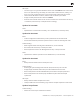
Functional Overview Refer to this diagram for symptoms related to MacBook Pro (17-inch, Early 2009) logic board connectors.
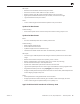
Block Diagram: MacBook Pro (17-inch, Early 2009) Refer to this diagram to see how modules are interrelated. CPU Penryn 2.66/2.93 GHz 1920x1200 LCD Display Internal Display Backlight LED Driver, APP001A Display Port µDVI-I/SL (mini DP) Display Port Mux LVDS Display Port GPU nVidia G96M Mono Amp LM48310 Display Port DDR3-1066 PCIE x16 SM Bus 0 SM Bus 1 Mono Amp LM48310 Mono Amp LM48310 RGMII Headphone & S/PDIF OUT Azalia Audio RealTek ALC885Q Headphone & S/PDIF IN Internal mic USB 2.
Block Diagram: MacBook Pro (17-inch, Mid 2009) Refer to this diagram to see how modules are interrelated. CPU Penryn 2.8/3.06 GHz 1920x1200 LCD Display Internal Display Backlight LED Driver, APP001A LPC Display Port µDVI-I/SL (mini DP) Display Port Mux LVDS Display Port GPU nVidia G96M Mono Amp LM48310 Display Port DDR3-1066 PCIE x16 SM Bus 0 SM Bus 1 Mono Amp LM48310 Mono Amp LM48310 RGMII Headphone & S/PDIF OUT Azalia Audio RealTek ALC885Q Headphone & S/PDIF IN Internal mic USB 2.
Liquid Submersion Indicators To help discover accidental damage to the computer, the top case includes spill sensors called liquid submersion indicators (LSI). The sensors are visible when the bottom case and most of the modules have been removed. Normally represented by small white dots, the LSIs turn red (indicated by the small, areas circled below) when they have come in contact with liquid, such as an accidental spill. For more information, refer to the Knowledge Base article HT3425: http://support.
can result in operational anomalies with the computer. Examples include not turning on, not waking from sleep, not charging the battery, or not recognizing the AC Adapter, among others. Don’t reset the SMC if the computer is unresponsive. An SMC reset should only be a last resort in cases where a hardware failure of the power management system is suspected.
Resetting the Parameter RAM (PRAM) To reset PRAM, 1. If the computer is on, turn it off. 2. Locate the following keys on the keyboard: Command, Option, P, and R. You will need to hold these keys down simultaneously in Step 4. Note: If the keyboard does not have an Option key, use the Alt key instead. 3. Turn on the computer. 4. Press and hold the Command-Option-P-R keys. Important: You must press this key combination before the gray screen appears. 5.
Display Issue: Pixel Anomalies When displaying a single color over the screen area, the LCD panel might show one or more pixels that are not properly lit. To determine if the display has an acceptable number of pixel anomalies, follow the steps below: 1. Set the display image to one of the following colors: all-white, all-red, all-green, all-blue, or all-black display.
Display Hinge Behavior The MacBook Pro models have a unique counterbalanced clutch system. The design provides a smooth, fluid feel when opening, closing, or positioning the display. The counterbalanced clutch system was designed so that when the display is vertical with respect to the ground, it will remain in place regardless of the angle of the base. Moving the display past vertical allows the hinges to release and the display to close. This is normal behavior and no repair is necessary.
Symptom Charts Follow the steps in the order indicated below. If an action resolves the issue, retest the system to verify. Note: A compilation of Quick Check tables is available at http://service.info.apple. com/QRS/en/quickreference.pdf. Note: There is no silkscreen text on final production logic boards. The photos shown with test points are from pre-production units and are solely for reference.
Deep Dive 2010-06-11 Check Result Action 1. Isolate peripherals as cause. Disconnect all peripherals and external devices and verify unit starts. Yes Suspect peripherals as cause. Reconnect each one at a time, verifying unit operation as external device is reinstalled. No Go to step 2 2. Reset SMC, and verify unit starts. (Alternative hardware SMC reset can be forced by shorting R5001 pads on logic board or removing all system power for 1 minute.
6. Inspect MagSafe power adapter. Verify AC adapter is correct wattage, compatible with product and works on known-good computer. Yes Power adapter is good, go to step 7 No Release stuck pin or replace adapter due to wire damage, not working or burned pins 7. Inspect MagSafe port on computer for physical damage, debris or metal fragments attracted to magnetic connector. Is MagSafe connector clean and free from defects? Yes Go to step 8 No Clean port assembly. Replace MagSafe board if necessary. 8.
Won’t Start Up Unlikely cause: display assembly, speakers, fan, camera, microphone Quick Check Symptom Quick Check Power but No start up • No startup chime, some video activity, Apple logo, startup spin dial • Startup chime with possible beep tones. • Fan, hard drive spin or optical drive reset sound • Sleep LED is on , blinking or went out • Caps Lock LED toggles when pressed 1. Reset SMC. 2. Verify startup process passes initial memory checks – no beep errors or flashing sleep LED indicators.
3. Reseat customer memory and/or swap in knowngood memory to isolate bad memory and replace defective parts. Yes Customer memory defective and replaced. Continue to verify startup process. Go to step 4 X02 No Should known-good memory fail in one or more slots, replace logic board. M07 4. Hold the Alt (Option) key during startup and verify there is a bootable hard drive shown in Startup Manager. Choose customer hard drive.
8. Use Disk Utility loaded from OS install disc to verify if hard drive is available on device list. Is customer hard drive listed in Disk Utility? Yes Customer hard drive available for inspections and repair. Go to step 10. No Hard drive not present, troubleshoot hard drive and cable. Go to step 9. 9. Troubleshoot hard drive and hard drive SATA cable with cable reseat and known-good part substitutions.
Intermittent Shutdown Unlikely cause: hard drive, optical drive Troubleshooting Shutdown Issues Before troubleshooting shutdown issues, always do the following: • Run the available Apple diagnostics to check for cause of previous shutdown(s). Running ASD also helps isolate any abnormal value reading from a thermal, voltage, or current sensor or from a fan speed meter.
Suggested steps for troubleshooting: • Reset SMC. • Check that AC cable, AC adapter and battery connections are secure to logic board. • Verify battery and power adapter sources using the Battery and Adapter test utility. Hardware-related system shutdown These shutdowns are due to temperature, voltage, current, fan speed or other hardware-related sensor values going out of range. • One of the temperature sensors reached a specified temperature limit.
Deep Dive Check Result 1. Activity related shutdowns: Reset SMC and PRAM and verify that shutdown issue still happens. Yes Check with known-good bootable drive: go to step 2 No Shutdown cause was related to SMC or Pram programmed shutdown settings or corruption, and was resolved by reverting them to default settings. 2. Booting from known-good bootable drive , verify that shutdown issue still happens. Yes Go to Power related shutdowns on step 3 No Shutdown events do not happen on known-good OS.
5. Check system running on battery only. Use known-good charged battery. Verify if shutdown/reset/sleep issues disappear when knowngood battery is used without AC adapter. Yes No Symptoms unchanged - Go to step 6 6. Check with known-good AC adapter source only Remove battery and use known-good AC adapter. Verify if the shutdown/reset/ sleep issues disappear with known-good adapter. Yes Faulty user’s AC adapter. Replace user’s AC adapter if AC cable and duckhead were confirmed good.
8. Verify if a thermal sensor or fan failure is reported in ASD or other available service utility. Yes -If fan not running failure, check for fan cable seating and retest. If same failure after retest replace fan with known-good fan and retest. If issue does not happen with known-good fan, replace user’s fan. -If an over temp failure reported, check for cause of over temp, like obstructed vent, dust in heatsink fin, clogged fan and retest.
Deep Dive Check Result 1. Characterize video issue Define whether the issue is a bad image with backlight OR no video issue. Verify whether some image even distorted is visible. Yes Bad image quality, go to step 5 No No image seen or no backlight, go to Step 2 2. Isolate Peripherals as cause Disconnect all peripherals, external devices, Express Card and display adapters if present and verify that video is displayed. Yes Suspect peripherals as cause.
6. Connect External video Connect known-good VGA/ DVI adapter to known-good display, press power button and close display to force main screen startup on external video. Verify that video is correct when displayed from external display. 7. Isolate LCD display detection Disconnect external monitor and reopen display and restart unit. Verify that sleep LED indicator goes off after internal LCD has been detected. 8.
9. Check for No Backlight Condition. Power on unit. Using a lamp or bright light source, inspect for faint image, and verify that any faint image appears. 10. Verify with Known good display assembly Connect known-good display assembly to system. 11. Verify with reseated backlight cable or replaced display assembly Verify that unit now has video and backlight. 2010-06-11 Yes Logo image visible - check and reseat LVDS cable connector on logic board. Inspect cables for damage near clutches: .
Battery Isn’t Recognized or Won’t Charge Unlikely cause: display assembly, speakers, optical drive, hard drive, trackpad Quick Check Symptom Quick Check Battery isn’t recognized or won’t charge • AC adapter • No MagSafe LED indicator • No orange charge indication • Battery status LEDs: - single chase - all flash - no LED 1. Check battery level and test AC power. 2. Refer to Deep Dive table for battery diagnostic testing. Deep Dive Check Result Action 1.
4. Does battery status indicate the battery is not recognized with a single LED on that chases back and forth 5 times? Yes Go to step 8 and tag battery as a possible P11 candidate. No Go to step 5 5. Does battery status indicate the battery is recognized but not charging with all LEDs blinking? Yes Go to step 8 and tag battery as a possible P10 candidate No Go to step 6 6.
11. Battery status LEDs not working - inspect button stuck or cable disconnect at logic board and reset SMC. Yes LED status now working. Go to step 3. No Go to step 12. 12. Remove system battery and connect and test a knowngood battery status indicator assembly. Do LEDs indicate a battery not recognized chase pattern? Yes Replace customer battery LED indicator assembly. Go to step 3 X03 No Replace customer logic board. M20 13. Open Apple System Profiler and click on the Power Tab on the left.
Kernel Panic/System Crashes Unlikely cause: Battery, Power Adapter Quick Check Symptom Quick Check Memory Issues/Kernel panic and freezes • Display notice of system kernel panic during start up and desktop use. • System freeze during use. • System freeze upon wake from sleep. 1. Reset SMC and clear PRAM 2. Remove suspect external devices. 3. Verify user memory is Apple-approved memory, and memory configuration matches memory installed. 4. Start up with shift key down for safe mode. 5.
4. Remove I/O device where possible to pinpoint faulty device: Yes - Disconnect camera cable from display assembly (for AirPort, Bluetooth, camera, and ambient light sensor). Camera cable can be disconnected without affecting startup and test. System starts up when I/O device removed, replace affected I/O device or module containing it. If AirPort card presence is crashing system, replace AirPort card. If still issue, replace display assembly (for Bluetooth, camera, or cable damage).
6. Disconnect display assembly and test with known-good display assembly. Verify that system now starts up without kernel panic/freeze. Yes Replace display assembly. No Go to step 7 7. Check for thermal values and fan running speed Run ASD to check for fan and sensors test, and verify that ASD does not report any overtemp, failing sensor, or fan.
Won’t Run on Power Adapter Alone Unlikely cause: RAM, display assembly, hard drive, optical drive, top case, speakers, camera, microphone Quick Check Symptom Quick Check Won’t Run on Power Adapter Alone 1. Verify proper wattage adapter is being used. Runs on battery but not on power adapter only. 2. Check for dirty or stuck pins on the MagSafe connectors, both on the adapter and the computer. 3. Connect the AC adapter to known-good power source. 4.
Power Adapter Issue Unlikely cause: logic board, RAM, display assembly, hard drive, optical drive, top case, speakers, camera, microphone Quick Check Symptom Quick Check Power Adapter Issue • No power • No Power LED • Non-operational • Stuck /broken pin 1. Connect AC adapters MagSafe connector to the computer. The LED on the connector should be green or amber. 2. Verify power cord, or plug, is firmly attached to AC adapter. 3. Verify AC power source is supplying AC power. 4.
4. Does the customer’s power adapter have stuck or bent pins on the MagSafe connector? Yes Replace power adapter. No Go to step 5 5. Does the cable or duckhead have visible damage? Yes Replace cable or duckhead. No Go to step 6 Yes Verify adapter with knowngood unit and customer unit and troubleshoot source of error No Replace power adapter. 6. Check that LED on MagSafe connector is displaying both green (if battery charged) and orange (when charging).
3. Disconnect any peripheral devices, cards, or cables attached to the unit. Verify the noise is gone. Yes Check for possible ground loop. No Go to step 6 4. Locate the source of the noise. Is the noise from an optical drive? Yes Check with a different media disc. Possible issue with disc label or out of balance media. If not related to media, and noise is above normal level, replace optical drive. No Go to step 5 Yes It is normal for drives to produce noise when they spin up or the heads move.
Burnt Smell / Odor Unlikely cause: Enclosure Quick Check Symptom Quick Check Burnt Smell / Odor 1. Disconnect AC adapter from the computer. Computer or power adapter emits an odor or smell of smoke. 2. Attempt to identify the source of the odor. Visual clues are component damaged like capacitor chip popped or burn marks. Deep Dive Check Result Action Code 1. Has the source of the odor been identified. Yes Replace the affected part.
3. Is the computer operating normally? Yes This could be related to normal operation. No Please refer to best related troubleshooting section. If after inspecting the unit you feel there is a possible safety issue with the computer or AC adapter, please notify Apple. Battery Leaking or Swollen Quick Check Symptom Quick Check Battery Leaking or Swollen • Computer wobbles • Trackpad button does not work • Deformed bottom case 1. Check if the battery is covered under a repair extension program.
Communications Ethernet Port/Device Issue Unlikely cause: power adapter, battery, speakers, optical drive, hard drive, fan, camera, microphone, top case, display assembly, AirPort card Quick Check Symptom Quick Check Ethernet Port/Device Issue • No Ethernet device present • Unable to access network resources • Ethernet device shows no connection • Ethernet device unable to get an IP address • Slow network performance 1.
2010-06-11 2. Isolate OS by booting from original install media. Verify Network Link status active by using Network Utility on install DVD. If the Ethernet interface (en0) Link Status is inactive, recheck physical connect and link activity indicator on hub/ switch. Yes Ethernet interface (en0) Link Status is active, go to step 3. No If connection is OK on knowngood system, replace logic board. 3. Verify if IP address is listed for the Ethernet interface in System Preferences: Network.
AirPort/Bluetooth: Defective Wireless Devices Unlikely cause: power adapter, battery, speakers, optical drive, hard drive, fan, camera, microphone, top case Caution: When testing an AirPort card connection, wait at least 5 seconds after shutdown before touching the camera cable connection to the logic board. Waiting less than that could damage the AirPort card.
2010-06-11 2. Run Clamshell Service Diagnostic utility and check for all devices presence. If not found, reseat the camera cable connection to the logic board. Yes Loose logic board connection. N04 No AirPort issue, go to step 3, Bluetooth issue go to step 7. 3. (AirPort) Verify the antenna connections to the AirPort card are not reversed or loose. Reseat antenna and I/O cable connections. Yes Loose connections or crossed antenna.
No/Poor Wireless Signal Unlikely cause: power adapter, battery, speakers, optical drive, hard drive, fan, camera, microphone, top case Quick Check Symptom Quick Check No/Poor Wireless Signal • Unable to find networks • Intermittent connection dropouts • Slow transfer speeds 1. Check for nearby interference sources in the 2.4/5GHz range such as microwave ovens and cordless phones (Knowledge Base HT1365). 2. Check that computer is within base station range – move closer to base station. 3.
3. Verify the antenna connections to the AirPort card are not reversed or loose. Reseat antenna and I/O cable connections. Yes Loose connections or crossed antenna No If the connectors are secure, antenna connections not reversed and show no signs of damage or wear, go to step 4. 4. Try a known-good AirPort antenna. Yes Replace AirPort antenna. No Continue to use known good antenna, go to step 5. 5. Try a known-good AirPort card. Yes Replace AirPort card.
2010-06-11 2. System Preferences has a Bluetooth panel. Ensure Bluetooth is on and discoverable. Are there any devices listed in pairing window? Yes Choose known-good device and establish a connection. Go to step 3. No Attempt Bluetooth repair, go to step 5. 3. Ensure a known-good Bluetooth device is on, in close range and in discoverable mode. Is computer pairing with known-good device? Yes Pairing verified, connect with user’s device, go to step 4 No Attempt Bluetooth repair, go to step 5. 4.
8. Continue to test a known-good Bluetooth device to determine if there is a disconnect. Do not allow computer to sleep during this test. Is link lost during test? Yes No Check for software update, 2.4 GHz radio interference or device low battery. If still losing link, replace Bluetooth card. If installed Bluetooth card is known-good or was already replaced, replace top case (for Bluetooth antenna). N14 N14 Known-good device passed test.
2. Run Clamshell Service Diagnostic utility and check for all devices presence. If not found, reseat the camera cable connection to the logic board. Is kernel panic resolved? Yes Go to step 4. No Go to step 3. 3. Isolate AirPort card by removing the I/O connection from the AirPort card. side. Reconnect camera cable connection to logic board. Is kernel panic resolved? Yes Go to step 4. No Go to M06 Kernel Panic / System Crashes. 4. Connect and test with a known-good AirPort card.
Wireless Performance Issue / Slow Connection • Slow or stalled data transfers • Intermittent connection dropouts 1. Check for nearby interference sources in the 2.4/5GHz range such as microwave ovens or cordless phones (Knowledge Base HT1365) 2. (AirPort) Check the number of users trying to use AirPort in the area for possible network congestion. Move closer to base station to improve signal reception. 3. (Bluetooth) Move devices closer together. 4. Check performance with a known-good system 5.
2010-06-11 3. Run Clamshell Service Diagnostic utility and check for all devices presence. If not found, reseat the camera cable connection to the logic board. Yes Loose logic board connection N04 No AirPort issue, go to step 4, Bluetooth issue, go to step 8. 4. (AirPort) Verify the antenna connections to the AirPort card are not reversed or loose. Reseat antenna and I/O cable connections.
Wireless Input Device Doesn’t Pair Unlikely cause: display assembly, logic board, optical drive, hard drive Quick Check Symptom Quick Check Wireless Input Device Doesn’t Pair • Can’t get the system to recognize the Bluetooth keyboard or mouse 1. Check Bluetooth System Preference is set to Discoverable. 2. Check Bluetooth device has fully charged batteries. 3. Check for Bluetooth software updates for both the device and Mac OS X. 4.
5. Run Clamshell Service Diagnostic utility and check for all devices presence. If not found, reseat camera cable with logic board. Is the Bluetooth radio present, on and pairing with a knowngood device? Yes Bad logic board connection. Issue resolved. No Go to step 6. 6. (Bluetooth) Enable Bluetooth and try a known-good Bluetooth card if available. Is pairing issue fixed? Yes Replace Bluetooth card. No Go to step 7. 7.
Display Display Anomalies Quick Check Symptom Quick Check Display Anomalies • Incorrect/missing colors • Distorted/blurred image • Pixel anomalies • Vertical/horizontal lines • Non-uniform brightness • Image flicker • Image persistence 1. Allow display to reach normal operating temperature for about 15 minutes before evaluating front-of-screen performance. 2. Check display preferences for use of custom display profile. 3. Check brightness setting. 4. Check for Software Updates. 5.
5. Verify if user’s issue is nonuniform brightness. Yes Go to Non-uniform Brightness Deep Dive. No LCD functioning OK. Deep Dive: Incorrect/Missing Colors 2010-06-11 Check Result Action Code 1. Verify display is listed in the System Profiler’s Graphics/ Displays device tree. Yes This ensures color profile can be matched with LCD. Go to step 2. No Go to N09. 2. Verify System Preferences Display Profile is valid for display being tested.
7. Substitute a known-good display assembly to test logic board video output. Is normal video restored? Yes Replace display assembly. L02 No Replace logic board. M04 Code Deep Dive: Distorted/Blurred Image Check Result Action 1. Sample image illustrates loss of LVDS data signals to LCD or a defective LCD panel. Inspect & reseat LVDS cable connection looking for damaged or bent pins. Is image restored with reseated cable connection? Yes Issue due to loose connection. Display issue resolved.
Deep Dive: Vertical/Horizontal Lines 2010-06-11 Check Result Action Code 1. Horizontal lines may be related to a failing RAM module. Verify if video issue only happens AFTER the Apple logo and the spinning wheel has appeared. Yes Issue only happens AFTER Apple logo and spinning wheel appears. Go to step 2. No Issues happens since startup. Go to step 5. 2. Start with shift key down (safe mode) to disable system extensions. Verify if issue still happens when booting in safe mode.
Deep Dive: Non-uniform Brightness Check 2010-06-11 Result Action 1. Determine if brightness uniformity issue is visible after display has warmed up for 15 minutes. Yes Go to step 2. No Display backlight can take several minutes to stabilize. 2. Check LVDS cable connection to logic board. Yes Reseat LVDS cable No Got to step 3 3. Determine if variation in uniformity appears excessive when compared to another similar unit. Yes Replace display assembly.
Defective Camera / Built-in iSight Not Operating Correctly Quick Check Symptom Quick Check Defective Camera • Camera not detected • No green LED for camera • Excessive blooming • Poor white balance • Poor focus • Green image • Image distortion 1. Check for Software Updates. 2. Verify camera lens and glass panel are clear of contaminants. Deep Dive 2010-06-11 Check Result Action Code 1. Launch System Profiler and confirm that “Built-in iSight” is listed under USB High-Speed Bus.
Blank / No Video Unlikely cause: Power adapter, speakers, ODD/HDD, fan, microphone, top case Quick Check Symptom Quick Check Blank / No Video • No video • No backlight 1. Check brightness setting 2. Attach known-good supported external display. 3. Boot from Mac OS X install DVD that came with computer. Deep Dive 2010-06-11 Check Result Action 1. Verify boot chime present when system restarted. Reset SMC and clear PRAM if necessary for proper start up. Is LCD video present? Yes Go to step 3.
6. Verify LCD video works with a known-good display assembly. Yes Replace display assembly. No Go to No Video symptom code flow. L03 Backlight Issue / No Backlight Unlikely cause: Power adapter, battery, speaker, ODD/HDD, fan microphone, top case Quick Check Symptom Quick Check Backlight Issue / No Backlight • Display not illuminated • Flashing, unstable or non uniform background lighting • Poor backlight at some or all settings Check that brightness setting is above minimum.
4. Swap memory with knowngood memory to determine if video issue is ram related.. 5. Inspect LVDS connectors and cable under magnification for pinched cables and damaged or bent pins. Do any of the connections appear to be defective? Yes Reseat or replace defective memory No Go to step 5 Yes Defective LVDS cable. Replace display assembly. Defective LVDS connector on logic board. Replace logic board. 6. Substitute a known-good display assembly to test logic board video output.
2. Verify display listed in the System Profiler’s Graphics/ Displays device tree is not disappearing intermittently (refresh System Profiler to observe). Yes Power and LCD panel ID are OK. Go to step 3. No Go to No Video symptom code flow. 3. Inspect and reseat the LVDS cable and camera cable connection between display and logic board. Also test if brightness setting is a contributing factor. Has flickering stopped? Yes Loose cable connection. Issue resolved. No Go to step 4. 4.
Cosmetic Defects Quick Check Symptom Quick Check Cosmetic Defects • Cracked LCD • Scorched or melted LCD • LCD impact damage 1. Determine damage caused by user/technician environment, accidental damage, or abuse. 2. Inform user/technician the failures are not covered by Apple warranties. Refer to http://www.apple.com/legal/warranty Uncategorized Symptom Quick Check Symptom Quick Check Uncategorized Symptom Verify whether existing symptom code applies to the issue reported by the user.
Mass Storage Hard Drive Read/Write Issue Unlikely cause: LCD, speakers, fan, camera, microphone Quick Check Symptom Quick Check Hard Drive Read/Write Issue Bad Sector/Defective Drive Formatting Issue • Cannot save documents • Read/Write error message • Hang when accessing or saving data 1. Boot from Install DVD. Verify S.M.A.R.T. status of drive using Disk Utility. 2. Repair disk using Disk Utility. 3. Erase disk and reinstall Mac OS using Installer. Deep Dive Check Result Action 1.
4. After reseating hard drive SATA and logic board connections, does known-good hard drive boot to desktop? Yes Reinstall user’s drive, go to step 2 No Suspect hard drive SATA cable, go to step 5. 5. Replace hard drive SATA cable and retest with known-good hard drive. Yes Reinstall user’s drive, go to step 2. X03 No Replace logic board. M19 6. Did user’s hard drive start up successfully? Yes Issue resolved. No Repair or replace hard drive, go to step 7. 7.
Deep Dive 2010-06-11 Check Result Action Code 1. Boot from Restore DVD and launch Disk Utility. Is hard drive available for Disk Utility to repair? Yes Go to step 2. No Go to step 3. 2. Did Disk Utility mount and repair hard drive successfully? Reseat hard drive if necessary. Yes Restart computer, go to step 6. No If computer has not been verified with a known-good hard drive, go to step 3; otherwise, go to step 7. 3.
Hard Drive Noisy Unlikely cause: LCD, speakers, fan, camera, microphone Quick Check Symptom Quick Check Hard Drive Noisy • Noise during start up • Noise during operation • Noise when drive is copying or saving data 1. Start up from Install DVD. Verify S.M.A.R.T. status of hard drive using Disk Utility. 2. Repair disk using Disk Utility. 3. Check for reported noise and compare with Knowledge Base article “Apple Portables: Hard Drives and Noise “ http://support.apple.
5. After installing new hard drive, do you still have drive noise? 6. After removing hard drive, verify if the system is still noisy. 7. Install a known-good hard drive and verify if the noise level is similar to user’s hard drive. Yes Remove hard drive and start up from external drive to test fan noise. Go to step 6. No Issue resolved. Yes Fan noise or optical drive noise likely to be the cause. See ODD Noisy table and Fan failures/Thermal issues table. No Go to step 7.
Deep Dive Check Result Action 1. Is optical drive listed in the device tree for serial-ATA devices in System Profiler? Yes Optical drive has power, inspect disc acceptance. Go to step 5. No Inspect hardware. Go to step 2 2. Verify all connections between logic board, flex cable, and optical drive are secure. Visually inspect cables and connectors for any debris, damage, or bent pins. Is optical drive now listed in System Profiler? Yes Optical drive has power, inspect disc acceptance. Go to step 5.
8. Does disc eject properly from optical drive? Yes Issue resolved. No Replace optical drive or top case that interferes with disc ejection. 9. With replacement flex cable and interconnect board, is disc now recognized? Yes Issue resolved. No Replace optical drive. If drive has already been replaced, then replace logic board.
2. Can optical drive read both CD and DVD known-good media? Yes Go to step 6 No Reading CD only or DVD only indicates laser issue, replace optical drive. J03 Optical drive cannot read any media reliably, go to step 3. 2010-06-11 3. Reseat cable connections at logic board and optical drive. Verify that media is now recognized and reads reliably. Yes Reseat resolved issue. X03 No Go to step 4. 4.
Optical Drive Not Recognized/Mount Unlikely cause: LCD, speakers, fan, camera, microphone Quick Check Symptom Quick Check Optical Drive Not Recognized/ Mount • Discs inject and eject, but do not appear in Finder 1. Use Apple System Profiler ATA section to see if the optical drive appears. 2. Serial-ATA section of Apple System Profiler will show any media inserted. 3. Check Finder Preferences: General and make sure “CD’s, DVD’s and iPods” is checked under “Show these items on the Desktop.” 4.
Optical Drive Noisy Unlikely cause: LCD, speakers, fan, camera, microphone Quick Check Symptom Quick Check Optical Drive Noisy • Noise during boot • Noise during operation • Noise when drive is copying or writing data 1. Test optical media in another drive of the same type in same type of computer to rule out media issue. 2. Check with known-good discs. Install discs that came with the computer. 3. Check to see if noise occurs without media in the drive.
2010-06-11 4. Disc spin should cease 30 seconds after mounting data CD on OS desktop. Is the noise related to disc spin? Yes Go to step 5. No Go to step 6. 5. Remove the optical drive and check for the correct seating of the brackets on the optical drive and in the top case. Reinstall drive in unit and retest. Verify if drive is still noisy. Yes Go to step 6. No Issue resolved. Optical drive was not properly mounted in enclosure. (Possible physical damage to optical drive.) 6.
Optical Drive Not Performing to Specs Unlikely cause: LCD, speakers, fan, camera, microphone Quick Check Symptom Quick Check Optical Drive Not Performing to Specs 1. Test optical media in another drive of the same type in same type of computer to rule out media issue. Read or write speeds slower than expected. 2. Check with known-good discs—Install discs that came with the computer. 3. For disc write issues, check with known-good media that performs well in another computer and drive of the same type.
4. Install and test with replacement optical drive SATA flex cable. Verify that media is now recognized and reads reliably. Yes Cable change resolved issue. X03 No Replace optical drive. (Mechanical damage to optical drive, if found) J03 (J05) 5. Test write data to compatible CD and DVD media. Verify burned media is recognized and reads reliably. Yes Issue resolved. No Replace optical drive.
Input/Output Devices USB Port Does Not Recognize Known Devices Unlikely cause: LCD, hard drive, optical drive Quick Check Symptom Quick Check USB Port Does Not Recognize Known Devices 1. Check the for latest software update. USB-wired keyboard/mouse or USB flash drive not recognized 2. Use Apple System Profiler to verify the computer recognizes the USB bus. 3. Test port with known good Apple keyboard or mouse. 4. Verify any USB hubs have sufficient power.
Built-in Keyboard Does Not Work Properly Unlikely cause: LCD, hard drive, optical drive Quick Check Symptom Quick Check Built-in Keyboard Does Not Work Properly • Keystrokes not recognized • Locks up • Displayed characters don’t match 1. In System Preferences: International: Input Menu, enable Keyboard Viewer. Select Show Keyboard Viewer from the Input Menu in the menu bar. Test the keyboard. 2. Confirm correct keyboard layout is selected. 3. Update to the latest system software. 4.
3. Disconnect and verify that keyboard flex cable is in good condition (no delamination or torn cable end, no missing or cracked tracks). Yes Go to step 4. No Replace top case. Go to step 5. K01 4. Reseat cable and check that flex cable end is fully inserted and aligned with connector on logic board, and that connector lock is closed. Verify that keyboard now functions properly. Reseat cable and verify with ASD that all keys are functional. Yes Issue resolved. K01 No Replace top case.
Built-in Trackpad Does Not Work Quick Check Symptom Quick Check Built-in Trackpad Does Not Work • Cursor does not move. • Select button of trackpad inoperable • Multiple touch features inoperable 1. Check for environmental factors such as humidity, hand lotion or jewelry. Check if user is touching the trackpad simultaneously with both hands. 2. Clean the trackpad surface (with the computer powered off) using a clean, dry, lint-free cloth. 3. Make sure all software and firmware updates have been applied.
6. Does the select button click? Verify trackpad alignment is proper and click-depth set screw is at factory setting. Yes All trackpad issues resolved. No Go to step 7 7. Does a known-good trackpad work? Yes Replace trackpad according to symptom found. - No mouse/trackpad response - Trackpad cursor not tracking properly - Trackpad button issues No Replace logic board.
2. Cover the ambient light sensor again. Did the keyboard backlight work? Yes Issue resolved. No Go to step 3. 3. In the Apple System Profiler, can you see the AirPort and Bluetooth cards? Yes The light sensor connection to logic board is likely good. Replace display assembly. No Go to step 4. 4. Reseat the keyboard backlight connection to the logic board. Does the keyboard backlight work now? Yes Issue resolved. No Go to step 5 5.
Deep Dive 2010-06-11 Check Result Action 1. In Apple System Profiler do you see “Apple Internal Keyboard/ Trackpad” listed under USB hardware devices? Yes Go to step 3. No Go to step 2. 2. Reset SMC and verify if keyboard/trackpad is now seen in Apple System Profiler. Yes Go to step 3. No Replace logic board. 3. Disconnect and verify that keyboard flex cable is in good condition (no delamination or torn cable end, no missing or cracked tracks). Yes Go to step 4. No Replace top case.
Built-in Trackpad Does Not Track Properly Unlikely cause: LCD, hard drive, optical drive Quick Check Symptom Quick Check Built-in Trackpad Does Not Track Properly • Cursor movement is random, uneven, or jumpy. • Cursor hangs or stalls along path. 1. Check for environmental factors such as humidity, hand lotion or jewelry. Check if user is touching the trackpad simultaneously with both hands. 2. Clean the trackpad surface (with the computer off) using a clean, dry, lint free cloth. 3.
6. Does a known-good trackpad work? Yes No Replace trackpad according to symptom found. - No mouse/trackpad response - Trackpad cursor not tracking properly - Trackpad button issues. Replace logic board. K02 K12 K13 M16 Apple Remote Inoperable Unlikely cause: LCD, hard drive, optical drive Quick Check Symptom Quick Check Apple Remote Inoperable • Remote is not recognized. 1. The computer is on and awake. 2.
Deep Dive Check Result Action Code 1. Open Photo Booth or iChat’s Video Preview window. Point Apple Remote at built-in iSight camera, press any button on remote, and verify that (as seen through the camera) a faint blinking light is on the remote. Yes Apple Remote works. Go to step 2. No Replace the remote’s battery. Go to step 2. 2. Verify that you can pair the Apple Remote with a knowngood system? Yes Go to step 3. No Replace the Apple Remote. Go to step 3. 3.
Deep Dive Check Result Action 1. Check System Preferences: Sound: Output and verify that no external speakers, “Digital Out,” or headphones are being reported connected when there is none present. Yes Audio-out port is not damaged. Go to step 3. No Go to step 2 2. With known-good headphone or speakers, plug in the audio output jack for several cycles. Verify that you get audio through external headphones/ speakers when connected. Yes Go to step 4 No Reseat the speaker connectors to logic board.
Deep Dive 2010-06-11 Check Result Action Code 1. Comparing internal speakers with headphones, is the distortion on both headphones and speakers? Yes Audio source or gain issue. Reset PRAM, adjust sound level in System Preferences: Sound: Output, and retest with known-good audio source and external speakers. Go to step 5. No Internal speaker issue. Go to step 2. 2. Use the Sound Output system preference to test the left and right speakers.
Express Card Will Not Insert Into Slot Unlikely cause: LCD, MLB, hard drive Quick Check Symptom Quick Check ExpressCard will not insert into ExpressCard Slot 1. The card must be a 34mm wide card with the top side oriented up and not be warped or damaged. ExpressCard does not fully seat into the slot 2. Clear any obstruction in the slot. Slot door does not open completely Deep Dive Check Result Action 1. Is the slot cover opening properly? Yes .
Express Card Not Recognized By System Unlikely cause: LCD, MLB, HDD/ODD Quick Check Symptom Quick Check ExpressCard is not recognized by the system. 1. Check correct drivers are installed for the ExpressCard. Card does not show up on the desktop or in System Profiler 2. Verify with known good USB and PCI Express based ExpressCards that the slot is good. Deep Dive Check Result Action 1.
FireWire Port Not Recognizing Known Devices Unlikely cause: LCD,HDD/ODD Quick Check Symptom Quick Check FireWire Port is not recognizing known devices 1. Check for latest software update. Attached FireWire device like digital camera or mass storage drive not recognized by the system 2. Use Apple System Profiler to verify the computer recognizes the FireWire bus. 3. Test port by connecting to another computer using FireWire Target Disk Mode. 4. Verify the FireWire cable is good. 5.
Mechanical Issues: Thermals and Enclosure Reset/Power Button Stuck Unlikely cause: LCD, hard drive, optical drive Quick Check Symptom Quick Check Reset/Power Button Stuck • System will not power on • System sounds bootROM unlock tone during startup • System automatically starts up repeatedly 1. Diagnose stuck button with SMC keyboard reset sequence 2. Inspect keyboard connection to logic board. 3. Try logic board power-on pads to determine open or closed power-on key.
2. Remove battery and AC power for 30 seconds to perform a manual SMC reset. Apply AC power. Does power-on key work when pressed? Yes SMC restored from power removal sequence. Power-on key now working properly. No Power-on key stuck or open. Go to step 3. 3. Inspect keyboard flex cable for loose or damaged connections. Align and reseat to flex cable to ensure proper connections. Does power-on key now work correctly? Yes Cable reseat restored poweron key operation.
Deep Dive Check Result Action 1. Is the system running as expected (compared to similar system)? Yes Use “Apple Portables: Operating Temperature” (Knowledge Base HT1778) to inform user it is operating normally. No Go to step 2. 2. Are there runaway applications? See “Runaway applications can shorten battery run time” (Knowledge Base TS1473). Yes Check with the vendor for compatibility and software update. No Go to step 3. 3. Fans are typically on at minimum speed.
8. Inspect and reseat connections to thermal sensors throughout the system, run test for sensor monitoring. Yes Thermal module or other sensor reseat resolved issue. No Replace logic board if sensor error. Go to step 9. 9. After logic board replacement, is the computer running as expected? Yes Bad logic board. Issue resolved. No Use minimum configuration troubleshooting to isolate the issue.
Apple Technician Guide Take Apart MacBook Pro (17-inch, Early 2009) © 2009 Apple Inc. All rights reserved.
General Information Vertical Insertion (JST) • • • Use black stick under cable to remove. Keep connector level to board when disconnecting and reconnecting. Press evenly when reconnecting or connector can be tipped up and not fully seated. Connector Types on Logic Board On the logic board are six types of connectors, each requiring special handling. Make sure you read these tips before disconnecting and installing the connectors.
• • BIL cable keyboard flex cable Caution: Use black stick to push the keyboard flex cable all the way into connector to prevent “no power” symptoms. Horizontal Install • • Pull connector, not cable, to remove. Slide connector into receptacle on same horizontal plane as board. Examples: • MagSafe cable on underside of board • battery power cable on underside of board Thin, Multi-Pin Horizontal Insert • • Use fingernails or tweezers to remove evenly.
Replacement Caution: When connecting cables, make sure they are fully connected. For the camera cable, place shim behind connector so it helps secure the cable. Replacement Caution: To prevent no video or a short to the logic board, be sure to place EMI gasket on camera cable— positioned precisely where shown—after cable is fully connected to logic board and shim is in place. Caution: When disconnecting camera cable, remove gasket and shim before disconnecting cable.
Icon Legend The following icons are used in this chapter: Icon Meaning Warning or Caution Check mark; make sure you do this Do not touch Temperature Concerns The normal operating temperature of this computer is well within national and international safety standards. Nevertheless, customers may be concerned about the generated heat. To prevent an unneeded repair, you can compare a customer’s computer to a running model, if available, at your repair site.
Bottom Case First Steps Warning: • Shut down computer. • Wait 10 minutes • Unplug all cables. • Put on ESD strap.
Removal Caution: To prevent scratches, use a protective cloth when working with metal tools. 1 Important: The screws at the sides and front of the computer must be removed and installed at an angle.
2 • • Remove 10 screws: 3 (13.5 mm) 922-8985 7 (3 mm) 922-8986 Replacement Note: Install screws in the order shown. 3 Use black stick to loosen and remove bottom case.
4 Warning: If performing any other repairs, be sure to disconnect the battery cable by its pull-tab. Replacement 1 When replacing a bottom case, retain the customer’s bottom case until the repair is complete. Before installing the replacement bottom case, write the serial number on the inside of the new bottom case. You might need a magnifying glass to read it. Refer to Transferring the Serial Number.
2 Install bottom case so that 4 clips snap onto top case.
Battery First Steps Remove: • Bottom case Before you begin this procedure, disconnect the battery from the logic board. Failure to do so could damage the computer.
Removal Important: Battery removal is only required when replacing the battery or the top case. Other internal repairs require disconnecting the battery cable but not removing the battery. 1 Use pull-tab to disconnect battery cable. 2 Remove 3 (5-mm) trilobe 922-8987 screws.
3 Peel up battery label from speaker only. 4 Without pulling cable, tilt out battery. Warning: Underside of battery is soft. • Do not puncture or press on battery. • Hold battery by edges only. • If setting battery aside, make sure surface is clean—free of dust, dirt, screws, etc. Warning: If mylar covering battery is punctured, do not re-use battery.
Replacement 1 Slide front edge of battery under 3 tabs. 2 Install screws. Note: If installing new battery, attach the new battery label (refer to battery label inbox instructions). 3 If performing other repairs, be sure to leave battery cable disconnected.
4 Connect battery cable using black stick or pull-tab, apply new battery label, and reassemble computer. 5 Press battery indicator light to check charge level.
Hard Drive Bracket First Steps Remove: • Bottom case Caution: Make sure data is backed up before removing the hard drive. Before you begin this procedure, disconnect the battery from the logic board. Failure to do so could damage the computer.
Tools Clean, soft, lint-free cloth • • ESD wrist strap and mat Magnetized Phillips #00 screwdriver Removal 1 Loosen 2 (5.5 mm) 922-xxxx captive screws. 2 Lift out bracket. Replacement Note: Make sure 2 rubber grommets are included in bracket before installing it.
Hard Drive First Steps Remove: • Bottom case • Hard drive bracket Caution: Make sure data is backed up before removing the hard drive. Before you begin this procedure, disconnect the battery from the logic board. Failure to do so could damage the computer.
Tools • • • • Clean, soft, lint-free cloth ESD wrist strap and mat Magnetized Phillips #00 screwdriver Torx T6 screwdriver Removal 1 Make sure hard drive bracket is removed. 2 Use pull tab to tilt hard drive out.
3 Hold hard drive by the sides only. 4 Disconnect hard drive connector.
Replacement 1 Make sure rubber grommets are included in top case before installing the hard drive. 2 Make sure 4 Torx T6 (922-xxxx) mounting screws are installed on drive. If replacement drive does not have mounting screws, transfer them from the old drive. 3 Attach connector, and tilt hard drive into front of top case.
Reinstalling Software that Came with the Computer Use the software install discs that came with the computer to reinstall Mac OS X and any applications that came with the computer. Choose either “Archive and Install,” which saves the existing files and settings, or “Erase and Install,” which erases all the data. Important: Apple recommends backing up data on the hard disk before restoring software.
Memory First Steps Remove: • Bottom case Before you begin this procedure, disconnect the battery from the logic board. Failure to do so could damage the computer.
Tools • • Clean, soft, lint-free cloth ESD wrist strap and mat Removal Memory cards must be: • 1.25 inch (3.18 cm) or smaller • 2 GB or 4 GB • 200-pin • PC3-8500 DDR3, 1066 MHz RAM 1 This computer comes with a minimum of 2 GB of 1066 MHz Double Data Rate 3 (DDR3) Synchronous Dynamic Random-Access Memory (SDRAM) installed. It has two slots that can accept SDRAM Small Outline Dual Inline Memory Modules (SO-DIMMs). The slots are stacked on the logic board under the bottom case.
2 Pull out the card. 3 Hold the card by the edges. 4 Do not touch the gold connectors. Note: New memory cards might have a harmless white residue on the gold connectors. Replacement 1 Install cards at an angle. If installing just one card, install it in lower slot.
2 Press card down. 3 If you installed additional memory, check that computer recognizes it.
Bluetooth Card and Holder First Steps Remove: • Bottom case Before you begin this procedure, disconnect the battery from the logic board. Failure to do so could damage the computer.
Tools Clean, soft, lint-free cloth • • • ESD wrist strap and mat Magnetized Phillips #00 screwdriver Black stick Removal 1 Remove 2 (2.2-mm) 922-8329 screws.
3 Use black stick to pry out Bluetooth holder. 4 Remove Bluetooth card and holder. 5 Turn over holder, and remove 2.3-mm screw (part of 076-1348 kit) from metal bracket. 6 Lift out card from holder.
Replacement 1 Remove any adhesive residue left on optical drive from Bluetooth holder. 2 Assemble Bluetooth card and bracket in holder.
Camera Cable Guide First Steps Remove: • Bottom case Before you begin this procedure, disconnect the battery from the logic board. Failure to do so could damage the computer.
Tools Clean, soft, lint-free cloth • • • ESD wrist strap and mat Magnetized Phillips #00 screwdriver Black stick Removal 1 Remove 2 (8-mm) 922-8645 screws. Replacement Note: Be sure to anchor the ground tab when reinstalling the screw closest to the display clutch cover. 2 Remove the camera cable guide.
LVDS Cable Guide First Steps Remove: • Bottom case Before you begin this procedure, disconnect the battery from the logic board. Failure to do so could damage the computer.
Tools Clean, soft, lint-free cloth • • • ESD wrist strap and mat Magnetized Phillips #00 screwdriver Black stick Removal 1 Locate LVDS cable. 2 To disconnect LVDS cable, grasp black tab and gently swing LVDS lock bar up and back to unlock the cable. 3 Slide cable out of connector by pulling the cable. Do not pull the black tab or lock bar.
4 Remove 2 (8-mm) 922-8645 screws. Replacement Note: Be sure to anchor the ground tab when reinstalling the screw closest to the display clutch cover. 5 Remove the LVDS cable guide.
Fans First Steps Remove: • Bottom case Before you begin this procedure, disconnect the battery from the logic board. Failure to do so could damage the computer.
Tools Clean, soft, lint-free cloth • • • ESD wrist strap and mat Magnetized Phillips #00 screwdriver Black stick Removal 1 Disconnect each fan cable. 2 Remove 6 (3.1-mm) 922-8754 screws. 3 Remove fan(s) from top case.
Optical Drive First Steps Remove: • Bottom case Caution: The optical drive is very fragile. Handle by the sides only. Before you begin this procedure, disconnect the battery from the logic board. Failure to do so could damage the computer.
Tools Clean, soft, lint-free cloth • • • ESD wrist strap and mat Magnetized Phillips #00 screwdriver Torx T6 screwdriver Removal 1 With a black stick, carefully pry optical cable straight up and off logic board. Important Replacement Note: Install flex cable vertically onto logic board connector. If not, logic board pins could bend, causing an undetected disc symptom. 2 • • 3 • • Remove 4 screws: 1 Torx T6 (3.1-mm) 922-xxxx at top case boss 3 Phillips #00 (3.
Replacement Caution: When connecting the camera cable, make sure it is fully connected; then place the shim behind the cable to secure it. Replacement Caution: To avoid a short to the logic board, be sure to place EMI gasket on camera cable— positioned precisely where shown—after cable is fully connected to logic board and shim is in place. 4 Tilt up optical drive. Replacement Note: If reusing optical drive, do not remove Bluetooth. Otherwise, refer to Bluetooth to transfer it to new optical drive.
5 Caution: The optical drive is very fragile.
Optical Drive Flex Cable First Steps Remove: • Bottom case • Optical drive Caution: The optical drive is very fragile. Handle by the sides only. Before you begin this procedure, disconnect the battery from the logic board. Failure to do so could damage the computer.
Tools • • • Clean, soft, lint-free cloth ESD wrist strap and mat Black stick Removal 1 Handle optical drive by sides only. 2 With a black stick or fingernail, carefully wiggle flex cable off optical drive.
Hard Drive Connector Cable First Steps Remove: • Bottom case • Hard drive bracket • Hard drive Caution: Make sure data is backed up before removing the hard drive. Before you begin this procedure, disconnect the battery from the logic board. Failure to do so could damage the computer.
Tools • • • • Clean, soft, lint-free cloth ESD wrist strap and mat Magnetized Phillips #00 screwdriver Black stick Removal 1 • • Remove 4 screws: 2 (1.8-mm) 922-8983 at shield 2 (2.2-mm) 922-8329 at cable 2 Remove shield. 3 Use black stick to disconnect cable and carefully pry cable up from adhesive.
Battery Indicator Light (BIL) Cable and Board First Steps Remove: • Bottom case • Hard drive bracket • Hard drive Caution: Make sure data is backed up before removing the hard drive. Before you begin this procedure, disconnect the battery from the logic board. Failure to do so could damage the computer.
Tools • • • • • Clean, soft, lint-free cloth ESD wrist strap and mat Magnetized Phillips #00 screwdriver Black stick Piece of tape Removal 1 Remove 2 (1.8-mm) 922-8983 screws from the shield. 2 Remove shield. 3 Place tape over BIL button on outside of top case. 4 Remove 2 (2-mm) 922-xxxx screws from BIL board.
5 Flip over board. 6 Lift lever to disconnect cable from BIL board and from logic board. Note: The tape will prevent the BIL button from falling out of top case.
Hard Drive Bracket, Front First Steps Remove: • Bottom case • Hard drive bracket • Hard drive Caution: Make sure data is backed up before removing the hard drive. Before you begin this procedure, disconnect the battery from the logic board. Failure to do so could damage the computer.
Tools • • • • Clean, soft, lint-free cloth ESD wrist strap and mat Magnetized Phillips #00 screwdriver Black stick Removal 1 Remove 2 (10-mm) 922-8648 screws. 2 Tilt out bracket. Replacement Note: Make sure 2 rubber gaskets are installed before installing screws.
Display Assembly First Steps Remove: • Bottom case • Camera cable guide • LVDS cable guide Before you begin this procedure, disconnect the battery from the logic board. Failure to do so could damage the computer.
Tools • • • • • Clean, soft, lint-free cloth ESD wrist strap and mat Magnetized Phillips #00 screwdriver Torx T6 screwdriver Foam wedge fixture Removal Caution: When disconnecting camera cable, remove gasket and shim before disconnecting cable. Caution: Avoid touching shim adhesive; body oils degrade adhesive. 1 Locate camera cable and Bluetooth connectors. 2 Peel EMI gasket off camera cable connector (A). 3 Disconnect camera cable from logic board (B).
Caution: Do not pull on the black tab or the LVDS lock bar. Pulling on the tab to remove the LVDS cable will likely result in the metal LVDS lock bar being torn off the cable body. This bar is only to be used to disengage the lock from the LVDS connector. A broken lock bar results in a display assembly replacement. 4 Peel EMI gasket off the LVDS cable, toward the fan. 5 To disconnect LVDS cable grasp black tab and gently swing LVDS lock bar up and back to unlock the cable.
7 Open the display to 90 degrees, and place the computer on the foam wedge service fixture. 8 Remove 6 (6.5-mm) Torx 922-8925 screws: 9 Separate display assembly from top case.
Replacement Important: Before returning a display assembly, be sure to • remove clutch cover • remove AirPort Card and transfer it to the new display assembly • reinstall clutch cover • remove and transfer the protective film from the replacement display to the defective display Important: Before installing a new display assembly, be sure to install the AirPort Card. With the computer assembled, test the AirPort card for normal operation.
4 With computer closed and flat on table, check alignment where the display meets the top case. 5 If necessary, slightly loosen the two center screws, adjust alignment, and resecure screws. 6 With the proper alignment verified, install the remaining screws (3-6) in the order shown while the computer is still closed. Replacement Caution: When connecting the LVDS and camera cables, make sure they are fully connected. For the camera cable, place shim behind connector so it helps secure the cable.
Display Hinge Behavior The MacBook Pro models have a unique counterbalanced clutch system and was designed so that when the display is vertical with respect to the ground, it will remain in place regardless of the angle of the base. Moving the display past vertical allows the hinges to release and the display to close. This is normal behavior and no repair is necessary. Refer to http:// support.apple.com/ kb/HT3304 for more information and to watch a video of the hinge behavior.
Display Clutch Cover First Steps Remove: • Bottom case • Camera cable guide • LVDS cable guide • Display assembly Before you begin this procedure, disconnect the battery from the logic board. Failure to do so could damage the computer.
Removal 1 Cover display face with clean, soft cloth. 2 Holding left hinge, slide clutch cover 1/4 inch (6.35 mm) away from the LVDS cable. 3 Press down on clutch cover to loosen 4 hooks inside.
4 Tilt up end of clutch cover as you roll it toward display face. 5 Remove clutch cover. Replacement 1 • • 2 Note shape of clutch cover: flat at bottom curved at top Make sure flat edge is at bottom of display.
3 Position clutch cover onto end with longer cable. 4 Lower clutch cover onto display assembly. 5 Listen for snapping sound as hooks engage. 6 Check for good fit.
Cable Clip for AirPort Card Refer to AirPort Card 2010-06-11 MacBook Pro (17-inch, Early 2009) Take Apart — Cable Clip for AirPort Card 173
AirPort Card First Steps Remove: • Bottom case • Camera cable guide • LVDS cable guide • Display assembly • Display clutch cover Before you begin this procedure, disconnect the battery from the logic board. Failure to do so could damage the computer.
Removal 1 Cover display with clean, soft cloth. 2 Remove 2.7-mm screw (922-8657) from cable clip. 3 Disconnect AirPort cable and remove cable clip.
4 Disconnect 2 AirPort antenna cables using a black stick. Replacement Note: Shorter antenna is at bottom. 5 Remove 2 (3-mm) screws (076-1343). 6 Lift out AirPort Card. Replacement 1 Make sure thermal pad is centered on AirPort Card rather than stuck to display assembly tab. 2 Important: Check the AirPort cable. At the end of the cable, on the metal part, there are two grounding fingers (two U-shaped marks).
3 Place the cable in the clip before connecting it to the AirPort card. 4 Connect AirPort cable and clip. 5 Make sure AirPort Card includes 4 foam pads.
6 Replace clutch cover. 7 Reassemble computer. Caution: When testing an AirPort card connection, wait at least 5 seconds after shutdown before connecting the camera cable connection to the logic board. Waiting less than that could damage the AirPort card.
Antenna Board First Steps Remove: • Bottom case • Camera cable guide • LVDS cable guide • Display assembly • Display clutch cover Before you begin this procedure, disconnect the battery from the logic board. Failure to do so could damage the computer.
Removal 1 Remove 4 (3.45-mm) screws (922-xxxx). 2 Lift out antenna board. Replacement 1 Make sure the AirPort antenna cable is routed in its channel. 2 Set the antenna board in the display assembly and install the screws.
Right Speaker/Subwoofer First Steps Remove: • Bottom case • Optical drive Before you begin this procedure, disconnect the battery from the logic board. Failure to do so could damage the computer.
Tools • • • • Clean, soft, lint-free cloth ESD wrist strap and mat Black stick Phillips #00 screwdriver Removal 1 • • 2 Remove 3 screws: 1 (2.6-mm) 922-8662 2 (12.4-mm) 922-8982 Disconnect speaker cable from logic board.
Logic Board First Steps Remove: • Bottom case • Memory • Fans Before you begin this procedure, disconnect the battery from the logic board. Failure to do so could damage the computer.
Tools • • • • Clean, soft, lint-free cloth ESD wrist strap and mat Black stick Phillips #00 screwdriver Removal 1 • • Remove 4 screws: 2 (3.1-mm) 922-8754 2 (1.8-mm) 922-8983 2 Lift away 2 shields.
3 • • • • • • • • • • • 4 Refer to Connector Types to carefully disconnect 11 cables: LVDS keyboard backlight camera optical drive right speaker IR/sleep trackpad keyboard Express card cage hard drive connector battery indicator light (BIL) Remove 6 (3.15-mm) 922-8754 screws.
5 Tilt logic board away from ports. 6 Holding board by edges, tilt it up and disconnect MagSafe connector.
Replacement If replacing the logic board with a new one, transfer: • left speaker • microphone cable • heatsink • memory 1 Install MagSafe board connector. 2 Keeping all cables away, install logic board screws in order shown. 3 Connect cables following the instructions in Connector Types.
Trackpad First Steps Remove: • Bottom case • Battery • Memory • Fans • Logic board Trackpad Kit 922-9009 includes: • trackpad • black label • 10 bottom case screws (3-mm and 13.
Removal 1 Remove 6 #000 (2-mm) Phillips screws from flexures. Discard old screws; they lose their ability to hold securely if reused. 2 Remove 4 T6 (4-mm) screws from flexure stiffeners. Keep screws. 3 Remove 1 tri-lobe set screw. Discard old screw. 4 Slide out stiffeners and flexures. Keep stiffeners. 5 Dispose of flexures (thin metal pieces); they are matched to each individual trackpad by thickness.
6 Carefully tilt up keyboard mylar as you peel up trackpad flex cable from adhesive on mounting ramp. Note: If a bar code label stays stuck to adhesive, be sure to remove it. 7 Hold trackpad and flex cable, and press down on edge closest to keyboard. 8 Slide trackpad down and back to clear supports in front edge of top case.
9 Tilt up top case, and spiral trackpad away from top case while carefully routing flex cable through hole.
Replacement Important: Dispose of old flexures, 6 short Phillips screws, and 1 tri-lobe set screw, and only use new ones included with trackpad kit. 1 Peel and adhere black label (included with new trackpad) to cover trackpad stiffener as shown. 2 Align new flexures on positioning posts. Note: This procedure will take patience and a steady hand. Try supporting the delicate flexures with a black stick.
3 Slide stiffeners over the flexures and align the screw holes. 4 Tighten 4 Torx T6 screws on stiffeners. 5 Carefully route flex cable through guide hole. 6 Spiral and pivot trackpad into place, inserting front edge first. Important: Minimize rubbing edges of trackpad against top case while installing. This could cause invisible cracks to form in the glass of the trackpad.
7 Loosely insert 6 short Phillips #000 screws into flexures. Do not tighten yet. 8 On the palm rest, insert one sticky (Post-It) note into gap on each of the four sides of trackpad.
9 Fold sticky notes over so that top case can be laid flat. 10 Tighten 6 short Phillips #000 screws at flexures. 11 Inspect that gaps between trackpad and top case are even on all sides. If not, loosen screws and adjust.
12 Insert tri-lobe #0 set screw. 13 Slowly turn set screw in small increments until trackpad has a normal clicking motion. Important: Do not overtighten set screw or you may damage trackpad. 14 Adhere flex cable to mounting ramp.
MagSafe Board First Steps Remove: • Bottom case • Memory • Fans • Logic board Before you begin this procedure, disconnect the battery from the logic board. Failure to do so could damage the computer.
Tools • • • Clean, soft, lint-free cloth ESD wrist strap and mat Phillips #00 screwdriver Removal Note: Although logic board is pictured here in relation to MagSafe board, the logic board would already be removed. 1 Remove 2 (7.6-mm) screws. 2 Lift out MagSafe board.
Replacement Caution: Plug in a disconnected adapter cable. 1 Making sure power is cut off, install MagSafe board screws. 2 Test port alignment by plugging in power cable from 4 angles. If port is off center and cable does not seat securely, loosen MagSafe screws, realign port with cable in place, and secure screws. If port seats correctly, continue. • • 3 Connect MagSafe cable to logic board. 4 Install logic board and remaining parts. 5 With computer fully assembled, test power with power cable.
Heatsink First Steps Remove: • Bottom case • Memory • Fans • Logic board Before you begin this procedure, disconnect the battery from the logic board. Failure to do so could damage the computer.
Tools • • • • • • Clean, soft, lint-free cloth ESD wrist strap and mat Magnetized Phillips #0 or #1 screwdriver Thermal grease syringe Alcohol pads Black stick Removal Caution: Hold heatsink by edges, not by the heat pipes: 1 Disconnect the thermal sensor cable, if provided, using a black stick. Note: Some heatsink models do not include a sensor cable.
2 Remove 8 (8.35-mm) 922-8799 screws. 3 Keeping heatsink parallel to logic board, gently wiggle the heatsink to loosen the bond to the board.
4 With a black stick, scrape off thermal grease and use alcohol pad to clean thermal pads and chips. Replacement Important: New heatsinks include pre-applied thermal grease. Follow steps 1-2 only if reinstalling the original heatsink. 1 Caution: The syringe contains enough thermal grease for 3 chips. Use a pen to mark the syringe in thirds.
2 Inject 1/3 of grease on the center of each chip 3 Important: Connect the thermal sensor cable, if provided. The computer will not function with the sensor disconnected. 4 Lower the heatsink over the logic board. 5 Install heatsink screws in order, 1/2 way first, then tighten the rest of the way.
Left Speaker First Steps Remove: • Bottom case • Memory • Fans • Logic board Before you begin this procedure, disconnect the battery from the logic board. Failure to do so could damage the computer.
Tools • • • • Clean, soft, lint-free cloth ESD wrist strap and mat Magnetized Phillips #00 screwdriver Black stick Removal Note: Do not touch the soft speaker cone.
2 Remove 2 (8.1-mm) 922-8720 screws. Replacement Note: If replacing the speaker, transfer microphone cable to replacement speaker.
Microphone Cable First Steps Remove: • Bottom case • Memory • Fans • Logic board • Left speaker Before you begin this procedure, disconnect the battery from the logic board. Failure to do so could damage the computer.
Removal Note: Do not touch the soft speaker cone. 1 Unroute microphone cable. Replacement Note: When transfering microphone cable to speaker, make sure cable is recessed within speaker body. 2 Turn over speaker, and carefully pry up the microphone gasket.
Express Card Cage First Steps Remove: • Bottom case • Memory • Fans • Logic board Before you begin this procedure, disconnect the battery from the logic board. Failure to do so could damage the computer.
Tools • • • • Clean, soft, lint-free cloth ESD wrist strap and mat Magnetized Phillips #00 screwdriver Black stick Removal 1 • • Remove 5 screws: 2 (4-mm) 922-8981 3 (2-mm) 922-8984 2010-06-11 MacBook Pro (17-inch, Early 2009) Take Apart — Express Card Cage 211
2 Carefully peel up flex cables from card cage. 3 Lift card cage from the top case. Replacement Note: Carefully move aside flex cables to slide card cage into place.
Top Case First Steps Remove: • Bottom case • Battery • Hard drive bracket • Hard drive • Memory • Camera cable guide • LVDS cable guide • Fans • Optical drive • Display assembly • Right speaker/ subwoofer • Logic board • MagSafe board • Express card cage Tools • • • Clean, soft, lint-free cloth ESD wrist strap Magnetized Phillips #00 screwdriver.
Removal With the first steps completed, the top case with keyboard is the remaining part. The top case includes: • battery indicator light (BIL) board and cable • hard drive connector cable • IR/sleep indicator cable • center bracket Replacement Note: Before assembling the computer, be sure to first transfer the Express card cage to the new top case.
Apple Technician Guide Views MacBook Pro (17-inch, Early 2009) © 2009 Apple Inc. All rights reserved.
Exploded View Main Assembly, 1 of 2: MacBook Pro (17-inch, Early 2009) Bottom Case 922-8930 Bluetooth 922-8965 Right Fan 661-5043 Left Fan 661-5044 Optical Drive, Super 661-4942 Flex Cable, Optical Drive 922-8919 Memory 661-5034, 2 GB 661-5035, 4 GB Hard Drive 661-4939, 5400, 320 GB 661-4940, 7200, 320 GB 661-4941, SSD, 128 GB 661-5017, SSD, 256 GB Bracket, Rear Hard Drive 922-8932 Flex Cable, Hard Drive 922-8920 Bracket, Front, Hard Drive 922-8931 Flex Protector, Hard Drive Cable 922-8935 Flex Pro
Main Assembly, 2 of 2: MacBook Pro (17-inch, Early 2009) Logic Board 661-5038, 2.66 GHz 661-5039, 2.
Display Assembly (both models) Display Clutch Cover, Pkg.
Main Assembly, 1 of 2: MacBook Pro (17-inch, Mid 2009) Bottom Case 922-9024 Bluetooth 922-8965 Right Fan 661-5043 Left Fan 661-5044 Optical Drive, Super 661-5202 Memory 661-5034, 2 GB 661-5035, 4 GB Hard Drive 661-5153, 5400, 500 GB 661-5154, 7200 500 GB 661-5199, SSD, 128 GB 661-5200, SSD, 256 GB Flex Cable, Optical Drive 922-8919 Bracket, Rear Hard Drive 922-8932 Flex Cable, Hard Drive 922-8920 Bracket, Front, Hard Drive 922-8931 Flex Protector, Hard Drive Cable 922-8935 Flex Protector, Keyboard C
Main Assembly, 2 of 2: MacBook Pro (17-inch, Mid 2009) Logic Board 661-5203, 2.8 GHz 661-5204, 3.
External Views Front View 2010-06-11 MacBook Pro (17-inch, Early 2009) Views — External Views 221
Port View A = MagSafe Power B = Gigabit Ethernet C = FireWire 800 D = USB 2.
Screw Location Diagrams Bottom Case All screw sizes shown are approximate and represent the total length of the screw.
Main Modules All screw sizes shown are approximate and represent the total length of the screw.
Display Assembly All screw sizes shown are approximate and represent the total length of the screw.
Feedback We want your feedback to help improve this and future Technician Guides! Please email any comments to: smfeedback4@apple.