Apple Technician Guide MacBook Pro (17-inch, Mid 2010) Updated 2010-06-11
Apple Inc. © 2010 Apple Inc. All rights reserved. Under the copyright laws, this document may not be copied, in whole or in part, without the written consent of Apple. Every effort has been made to ensure that the information in this document is accurate. Apple is not responsible for printing or clerical errors. Apple 1 Infinite Loop Cupertino, CA 95014-2084 USA + 1 408 996 1010 www.apple.com Apple, the Apple logo, Mac, MacBook, and Macintosh are trademarks of Apple Inc., registered in the U.S.
MacBook Pro (17-inch, Mid 2010) Contents Manual Updates 8 Updated 11 June 2010 8 Updated 14 May 2010 8 Feedback 8 Basics Overview 10 Specifications 10 Note About Images in This Manual 11 Battery Precautions 11 Battery Removal: Tri-Lobe Microstix #2 Screws 11 Serial Number Location 12 Serial Number On Bottom Case 12 Transferring the Serial Number 13 General Information 14 Required Tools 14 The Glass Panel 15 Keycap Replacement 15 Troubleshooting General Troubleshooting 17 Update System Software 1
Symptom Charts 24 Startup and Power Issues 24 No Power 24 Won’t Start Up 27 Intermittent Shutdown 30 No Video/Bad Video 34 Battery Isn’t Recognized or Won’t Charge Kernel Panic/System Crashes 40 Battery Run Time Too Short 43 Won’t Run on Power Adapter Alone 43 Power Adapter Issue 44 Noise / Hum / Vibration 46 Burnt Smell / Odor 48 Battery Leaking or Swollen 49 Uncategorized Symptom 49 Communications 37 50 Ethernet Port/Device Issue 50 AirPort/Bluetooth: Defective Wireless Devices 52 No/Poor Wireless S
Built-in Keyboard Does Not Work Properly 88 Specific Keys Don’t Work 89 Built-in Trackpad Does Not Work 90 Built-in Keyboard Has Dim or No Keyboard Backlight Built-in Keyboard Is Not Recognized 93 Built-in Trackpad Does Not Track Properly 94 Apple Remote Inoperable 95 Built-in Speaker Has No Audio 97 Distorted Sound from Internal Speaker 98 Audio: Microphone 99 Express Card Will Not Insert Into Slot 100 Express Card Not Recognized By System 101 Camera Issues 103 FireWire Port Not Recognizing Known Devices 1
Fans 142 AirPort/Bluetooth Flex Cable Optical Drive 144 146 Optical Drive Flex Cable 150 Hard Drive Connector Cable 152 Battery Indicator Light (BIL) Cable and Board Hard Drive Bracket, Front Display Assembly 157 159 Removal 160 Replacement 161 Display Hinge Behavior Display Clutch Cover 163 164 Removal 165 Replacement 166 AirPort/Bluetooth Holder AirPort/Bluetooth Card 169 172 Right Speaker/Subwoofer Logic Board 178 Removal 179 Replacement 182 Trackpad 184 Removal 185 Replacement 188
Top Case 209 Views Exploded View 213 Display Assembly 213 Main Assembly, 1 of 2 214 Main Assembly, 2 of 2 215 External Views 216 Front Views 216 Port View 217 Slot Drive View 218 Rear View 218 Screw Locations 219 Bottom Case 219 Battery, AirPort/Bluetooth Holder, Fans Optical Drive, AirPort/Bluetooth Card Logic Board 222 Battery Indicator Light (BIL), Heatsink Left Speaker, Right Speaker 224 Cable Guides from Display 225 Display Assembly 226 Front Hard Drive Bracket, ExpressCard MagSafe Board, Track
Manual Updates Updated 11 June 2010 Troubleshooting: • General Troubleshooting: Resetting the System Management Controller (SMC): Updated steps 3 and 4 Updated 14 May 2010 Basics: • Serial Number Location: Transfering the Serial Number: Added reference to serial number format article CP1099 • General Information: Required Tools: Updated versions of Apple Service Diagnostic and Apple Hardware Test • General Information: Keycap Replacement: Added section about new keycap replacement kit Troubleshooting: • Sy
Apple Technician Guide Basics MacBook Pro (17-inch, Mid 2010) © 2010 Apple Inc. All rights reserved.
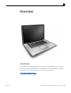
Overview Specifications The MacBook Pro (17-inch, MId 2010) computer features a 2.53 GHz Intel Core i5 or 2.66 GHz Intel Core i7 processor, NVIDIA GeForce GT 330M graphics processor, and aluminum unibody enclosure. For full technical specifications, refer to AppleCare Tech Specs: http://support.apple.
Note About Images in This Manual Because a pre-production model was used for most of the images shown in this manual, you may notice small differences in appearance between the image pictured and the computer you are servicing. However, although the appearance may differ, the steps and sequence are the same unless noted. Screw sizes shown are approximate and indicate the total length including the screw head.
Serial Number Location Serial Number On Bottom Case Turn over the computer to see the serial number etched on the bottom case near the hinge.
Transferring the Serial Number When replacing a bottom case, retain the customer’s bottom case until the repair is complete. Before installing the replacement bottom case, use a fine tip permanent marker to write the original serial number clearly and legibly in uppercase box letters directly onto the inside of the new bottom case. CAUTION: Take great care in deciphering the small typeface of the etched serial number on the bottom case. You might need a magnifying glass to see it clearly.
General Information Required Tools Caution: To prevent scratches or other cosmetic damage to the computer housing, use a soft cloth as a protective layer when removing and installing the external screws.
The Glass Panel Warning: The glass panel s not a serviceable part. If the glass is broken or scratched, replace the display assembly. Attempting to remove the glass can permanently shatter the display face and damage other parts. To clean the glass panel, use the Apple polishing cloth (922-8245) and iKlear Apple Polish or Brillianize anti-static spray cleaning solution. Alternatively, IPA (isopropyl alcohol) can be used.
Apple Technician Guide Troubleshooting MacBook Pro (17-inch, Mid 2010) © 2010 Apple Inc. All rights reserved.
General Troubleshooting Update System Software Important: Whenever possible before beginning troubleshooting, ensure the latest software and firmware updates have been applied. Apple Service Diagnostics Run Apple Service Diagnostic to determine if any of the thermal sensors are malfunctioning. Replace any failing sensors. See chart below for correlation between error code and part.
Hardware vs. Software For information on how to isolate a hardware issue from a software issue, refer to: TS1394—Mac OS X: Troubleshooting installation and software updates HT2956—Troubleshooting Mac OS X installation from CD or DVD For information on how to troubleshoot a software issue, refer to: HT1199—Mac OS X: How to troubleshoot a software issue
Functional Overview Refer to this diagram for symptoms related to MacBook Pro (17-inch, Mid 2010) logic board connectors.
Block Diagram, MacBook Pro (17-inch, Mid 2010) Refer to this diagram to see how modules are interrelated.
Liquid Contact Indicators Liquid contact indicators (LCI) have been added to specific locations on current Mac portables to help determine if systems have been damaged by liquid. The sensors are only visible when the bottom case and some of the modules have been removed. Normally represented by small white dots, the LCIs turn red when they have come in contact with liquid, such as an accidental spill.
Resetting the Parameter RAM (PRAM) To reset PRAM, 1. If the computer is on, turn it off. 2. Locate the following keys on the keyboard: Command, Option, P, and R. You will need to hold these keys down simultaneously in Step 4. Note: If the keyboard does not have an Option key, use the Alt key instead. 3. Turn on the computer. 4. Press and hold the Command-Option-P-R keys. Important: You must press this key combination before the gray screen appears. 5.
Display Issue: Pixel Anomalies When displaying a single color over the screen area, the LCD panel might show one or more pixels that are not properly lit. To determine if the display has an acceptable number of pixel anomalies, follow the steps below: 1. Set the display image to one of the following colors: all-white, all-red, all-green, all-blue, or all-black display.
Symptom Charts Follow the steps in the order indicated below. If an action resolves the issue, retest the system to verify. Note: A compilation of Quick Check tables is available at http://service.info.apple. com/QRS/en/quickreference.pdf. Note: There is no silkscreen text on final production logic boards. The photos shown with test points are from pre-production units and are solely for reference.
2. Reset SMC (remove all system power for 1 minute), and verify unit starts. Can system start up after SMC reset. Yes Corrupt SMC state preventing power on. Issue resolved with SMC reset. No Go to step 3 Yes System can start up from known-good battery -original battery possibly at fault or needs to be charged. Continue to verify original battery then AC adapter use and battery charging. Go to step 4. No System will not power using known-good battery only. Go to step 5 4.
7. Inspect MagSafe port on computer for physical damage, debris or metal fragments attracted to magnetic connector. Verify if MagSafe connector is clean and free from defects. Yes Go to step 8 No Clean port assembly. Replace MagSafe board if necessary. 8. Verify adapter status LED turns on green then orange indicating power and battery charge in progress. A green LED can indicate a full battery, removal of battery or battery not recognized. Yes System starts and has power.
Won’t Start Up Unlikely cause: display assembly, speakers, fan, camera, microphone Quick Check Symptom Quick Check Power but No start up • No startup chime, some video activity, Apple logo, startup spin dial • Startup chime with possible beep tones. • Fan, hard drive spin or optical drive reset sound • Sleep LED is on , blinking or went out • Caps Lock LED toggles when pressed 1. Reset SMC. 2. Verify startup process passes initial memory checks – no beep errors or flashing sleep LED indicators.
3. Reseat original memory and/or swap in known-good memory to isolate bad memory and replace defective parts. Yes Original memory defective and replaced. Continue to verify startup process. Go to step 4 X02 No Should known-good memory fail in one or more slots, replace logic board. M07 4. Hold the Alt (Option) key during startup and verify there is a bootable hard drive shown in Startup Manager. Choose original hard drive. Verify if system can start up from this drive.
8. Use Disk Utility loaded from OS install disc to verify if hard drive is available on device list. Verify if original hard drive is listed in Disk Utility. Yes Original hard drive available for inspections and repair. Go to step 10. No Hard drive not present, troubleshoot hard drive and cable. Go to step 9. 9.
Intermittent Shutdown Unlikely cause: hard drive, optical drive Troubleshooting Shutdown Issues Before troubleshooting shutdown issues, always do the following: • Run the available Apple diagnostics to check for cause of previous shutdown(s). Running ASD also helps isolate any abnormal value reading from a thermal, voltage, or current sensor or from a fan speed meter.
Suggested steps for troubleshooting: • Reset SMC. • Check that AC cable, AC adapter and battery connections are secure to logic board. • Verify battery and power adapter sources using the Battery and Adapter test utility. Hardware-related system shutdown These shutdowns are due to temperature, voltage, current, fan speed or other hardware-related sensor values going out of range. • One of the temperature sensors reached a specified temperature limit.
Deep Dive Check Result 1. Activity related shutdowns: Reset SMC and PRAM and verify that shutdown issue still happens. Yes Check with known-good bootable drive: go to step 2 No Shutdown cause was related to SMC or Pram programmed shutdown settings or corruption, and was resolved by reverting them to default settings. 2. Booting from known-good bootable drive , verify that shutdown issue still happens. Yes Go to Power related shutdowns on step 3 No Shutdown events do not happen on known-good OS.
6. Check with known-good AC adapter source only Remove battery and use known-good AC adapter. Verify if the shutdown/reset/ sleep issues disappear with known-good adapter. Yes Faulty user’s AC adapter. Replace user’s AC adapter if AC cable and duckhead were confirmed good. No Symptoms unchanged - Go to Hardware-related shutdowns on step 7 7. Hardware-related shutdowns: Run ASD and verify if a sensor failure is reported.
9. Isolate if issue solved Verify if shutdown/issue does not happen anymore after part exchange. Yes Issue fixed No Replace logic board with corresponding symptom: -if for thermal error cause -if for other cause M18 M08 No Video/Bad Video Unlikely cause: hard drive, optical drive, top case, battery, power adapter Quick Check Symptom Quick Check Power, but No Video • Power • No video • fan, hard drive spin, or optical drive reset sound • sleep LED is on or went on • light if Caps Lock pressed 1.
3. Adjust Brightness Power-on unit , attempt to adjust brightness to maximum using brightness (F1/F2) keys and verify if video is displayed. Yes Video displayed - Brightness set to minimum, panel backlight was inadvertently turned off. If backlight returns to low check for stuck F1 key on keyboard. No Go to Step 4 Yes Corrupt SMC State preventing video. No Go to Step 5 5. Reset PRAM. If no action, use external keyboard with same sequence. Verify if system video is displayed.
8. Check sleep sensor condition. If display assembly sleep sensor is stuck in a closed state, video will appear on internal display temporarily until the system sleeps. Disconnect BIL/ sleep cable and restart unit without external display. Verify if system starts up with video on internal display stays on and does not go into sleep mode. Yes Sleep sensor was stuck or had shorted cable. Replace BIL/ sleep sensor cable. No Symptoms unchanged - Go to Step 9 9. Check for No Backlight Condition.
Battery Isn’t Recognized or Won’t Charge Unlikely cause: display assembly, speakers, optical drive, hard drive, trackpad Quick Check Symptom Quick Check Battery isn’t recognized or won’t charge • AC adapter • No MagSafe LED indicator • No orange charge indication • Battery status LEDs: - single chase - all flash - no LED 1. Check battery level and test AC power. 2. Reset SMC by pressing the (left) Shift-ControlOption keys along with the power button once. 3.
5. Verify if battery status indicates the battery is recognized but not charging with all LEDs blinking. Yes Go to step 8 and tag battery as a possible P10 candidate No Go to step 6 6. Verify if battery status indicates battery charge and flash the next level 5 times. Yes Original battery charging, check battery condition. Go to step 13 No Flashing first LED only, go to step 7 (P10) No battery status LEDs on, go to step 11 7.
13. Open Apple System Profiler and click on the Power Tab on the left. Verify if the battery cycles amount is over 1000 cycle counts. Yes Battery has been consumed, and customer will need to purchase a replacement. No Go to step 14. 14. Verify that battery is less than a year old. Yes Go to step 16 No Battery warranty expired, go to step 15 15. Considering the age of the battery greater than one year old, verify if the health of the battery is “Good” according to system profiler.
Kernel Panic/System Crashes Unlikely cause: Battery, Power Adapter Quick Check Symptom Quick Check Memory Issues/Kernel panic and freezes • Display notice of system kernel panic during start up and desktop use. • System freeze during use. • System freeze upon wake from sleep. 1. Reset SMC and clear PRAM 2. Remove suspect external devices. 3. Verify user memory is Apple-approved memory, and memory configuration matches memory installed. 4. Start up with shift key down for safe mode. 5.
4. Remove I/O device where possible to pinpoint faulty device: Yes - Disconnect camera cable from display assembly (for, camera, and Ambient Light Sensor). Camera cable can be disconnected without affecting startup and test. -If Camera cable connection is crashing system, replace display module for damaged Camera/ALS cable. - Disconnect AirPort/Bluetooth card to isolate AirPort/ Bluetooth functionality. - Disconnect optical drive cable to isolate optical drive.
6. Disconnect display assembly and test with known-good display assembly or external monitor. Verify if system now starts up without kernel panic/ freeze. Yes Replace display module. No Go to step 7 7. Check for thermal values and fan running speed Run ASD to check for fan and sensors test, and verify if ASD does not report any overtemp, failing sensor, or fan.
Battery Run Time Too Short Quick Check Symptom Quick Check Battery Run Time Too Short 1. Check if the battery is covered under a repair extension program. Use the “Portable Computer Battery Screening Process for Apple Service Providers” (Knowledge Base CP165). Battery runs out of power very quickly (less than two hours) 2. Verify no applications have runaway processes with the CPU. See “Runaway applications can shorten battery runtime” (Knowedge Base TS1473). 3.
Deep Dive Check Result Action Code 1. With battery removed, verify if a known-good AC adapter starts up ,runs the system and shows MagSafe LED status. Yes Confirm user’s AC adapter as bad and replace. P14 No Verify MagSafe board cable seating to logic board. Go to step 2 2. Verify if a known-good power adapter’s LED light up either green or amber. Yes SMC on logic board senses AC power adapter. Go to step 3 No Replace the MagSafe board. Go to step 3. 3.
Deep Dive Check Result 1. Verify if the MagSafe LED is green or amber while connecting a known-good AC adapter on system. Yes SMC on logic board senses AC power adapter and enabled power. Go to step 4. No Verify MagSafe interconnect board is connected to logic board. Go to step 2 2. Verfiy that the unit runs on a known-good AC power adapter only. Yes Issued resolved. No Replace the MagSafe interconnect board. Go to step 3. 3.
Noise / Hum / Vibration Unlikely cause: RAM, display assembly, top case, camera, microphone, battery Quick Check Symptom Quick Check Noise / Hum / Vibration 1. Verify and reproduce the source of the noise from the computer / adapter with the customer. Computer or AC adapter emits a noise or vibration. 2. If the AC adapter is the source of the noise disconnect and try a known-good adapter. ( a small amount of hum or vibration is normal with AC adapters ).
5. Verify if the noise is coming from the hard drive. 6. Verify if the noise is coming from the fan. 7. Noise maybe related to interference from other electrical devices operating near the computer, or on the same AC power source. Verify if noise is gone when operating in a different location on a different AC circuit. 2010-06-11 Yes It is normal for drives to produce noise when they spin up or the heads move. Replace drive if noise is above normal levels.
Burnt Smell / Odor Unlikely cause: Enclosure Quick Check Symptom Quick Check Burnt Smell / Odor 1. Disconnect the battery and AC adapter from the computer. Computer or power adapter emits an odor or smell of smoke. 2. Attempt to identify the source of the odor. Visual clues are component damaged like capacitor chip popped or burn marks. Deep Dive Check Result 1. Verify if the source of the odor has been identified. 2. Verify if there are any burn marks visible on components. 3.
Battery Leaking or Swollen Quick Check Symptom Quick Check Battery Leaking or Swollen • Trackpad button does not work • Battery pack case has opened. • Bottom cover cannot be reinstalled 1. Check if the battery is covered under a repair extension program. Reference: MacBook, MacBook Pro (15-inch) or MacBook Pro (17-inch) with swollen battery article (Knowledge Base TS2358). 2.
Communications Ethernet Port/Device Issue Unlikely cause: power adapter, battery, speakers, optical drive, hard drive, fan, camera, microphone, top case, display assembly, AirPort / Bluetooth card Quick Check Symptom Quick Check Ethernet Port/Device Issue • No Ethernet device present • Unable to access network resources • Ethernet device shows no connection • Ethernet device unable to get an IP address • Slow network performance 1.
2010-06-11 3. Verify if IP address is listed for the Ethernet interface in System Preferences/Network. Connect computer to network with known-good DHCP IP allocation, ensuring static DHCP maps or MAC address filtering is not preventing address allocation. Note: DHCP allocation may not be instantaneous depending on network. Retest and verify if you obtain a valid IP address.. Yes Go to step 4. No If connection is OK on knowngood system, replace logic board. 4.
AirPort/Bluetooth: Defective Wireless Devices Unlikely cause: power adapter, battery, speakers, optical drive, hard drive, fan, camera, microphone, top case Caution: When testing an AirPort/Bluetooth card connections, wait at least 5 seconds after shutdown before touching the AirPort/Bluetooth flex cable connections to card and to the logic board .Waiting less before touching could damage the AirPort/Bluetooth card.
Deep Dive Check Result 1. Open System Profiler, check to see if AirPort and Bluetooth are recognized. 2010-06-11 Action Yes If AirPort and Bluetooth interfaces are detected in System Profiler: - for Airport-related issues ensure that MAC address filtering is not enabled on the base station, and go to step 5. - for Bluetooth-related issues ensure that target devices are set to discoverable, and go to step 8. No If Airport or Bluetooth interfaces are not detected in System Profiler, go to step 2. 2.
6. (AirPort) Try a known-good Bluetooth/Airport card and verify if it fixes the issue. Yes Replace original Bluetooth/ Airport card. No Continue to use known-good Bluetooth/Airport card, go to step 7. 7. (AirPort) Install a known-good display module to test with known-good AirPort antennas Verify if it fixes the issue. Yes Replace original display module (Airport antennas are part of display module) and reinstall original Bluetooth/ Airport card. 8.
No/Poor Wireless Signal Unlikely cause: power adapter, battery, speakers, optical drive, hard drive, fan, camera, microphone, top case Quick Check Symptom Quick Check No/Poor Wireless Signal • Unable to find networks • Intermittent connection dropouts • Slow transfer speeds 1. Check for nearby interference sources in the 2.4/5 GHz range such as microwave ovens and cordless phones (Knowledge Base HT1365). 2. Check that computer is within base station range – move closer to base station. 3.
2. Verify if both antennas connections to the AirPort card are not reversed or loose. Reseat antennas connections. Yes Loose connections or crossed antenna No Check antenna for reversed connections or signs of damage or wear. If issue persists, go to step 3. 3. Install a known-good AirPort/ Bluetooth card , retest and verify if issue is fixed. Yes Replace user’s AirPort/ Bluetooth card. No Continue to use known good AirPort/Bluetooth card, go to step 4. 4.
Bluetooth Wireless Input Device Loses Connection Unlikely cause: display assembly, speaker assembly, optical drive, hard drive Quick Check Symptom Quick Check Bluetooth Wireless Input Device Loses Connection Check Bluetooth input device has fully charged batteries. Check with known-good Bluetooth input device Check that all system and device available software and firmware updates have been applied. Deep Dive Check 2010-06-11 Result Action 1.
5. Reseat Bluetooth antenna connector on AirPort/ Bluetooth card and retest. Verify if Bluetooth is enabled and can pair with a knowngood device. Yes Loose Bluetooth antenna connection. No Go to step 6. 6. Install and test a known-good Bluetooth/Airport card and retest. Verify that Bluetooth is enabled and can pair with a known-good device. Yes Replace user’s Bluetooth/ Airport card. No Go to step 7. 7.
AirPort Card: Kernel Panic Unlikely cause: power adapter, battery, speakers, optical drive, hard drive, fan, camera, microphone, top case Quick Check Symptom Quick Check AirPort Card: Kernel Panic • Kernel panic on boot • Kernel panic or freezing while attempting to connect to Wi-Fi networks • Kernel panic while transferring data on Wi-Fi networks. 1. Isolate OS by booting from original install media (10.6.x). Attempt to connect to Wi-Fi network. 2.
Wireless Performance Issue / Slow Connection Unlikely cause: power adapter, battery, speakers, optical drive, hard drive, fan, camera, microphone, top case Quick Check Symptom Quick Check Wireless Performance Issue / Slow Connection • Slow or stalled data transfers • Intermittent connection dropouts 1. Check for nearby interference sources in the 2.4/5 GHz range such as microwave ovens or cordless phones (Knowledge Base HT1365) 2.
2. Turn off Bluetooth. Retest AirPort performance. Refer to Knowledge Base TS1809. Verify if performance issue is fixed. Yes Possible AirPort interference from the Bluetooth card. Change AirPort base station channel. (Knowledge Base TS1809.) No -If AirPort-related issue, go to step 3. -If Bluetooth-related issue, go to step 6. 2010-06-11 3. (AirPort) Verify that antenna connections to the AirPort card are not reversed or loose.
Wireless Input Device Doesn’t Pair Unlikely cause: display assembly, logic board, optical drive, hard drive Quick Check Symptom Quick Check Wireless Input Device Doesn’t Pair • Can’t get the system to recognize the Bluetooth keyboard or mouse 1. Check Bluetooth System Preference is set to Discoverable. 2. Check Bluetooth device has fully charged batteries. 3. Check for Bluetooth software updates for both the device and Mac OS X. 4.
5. Verify if Bluetooth antenna connection to the AirPort/ Bluetooth card is not loose. Reseat antenna connection and verify if pairing issue is fixed. Yes Loose Bluetooth antenna connection. Issue resolved. No Go to step 6. 6. (Bluetooth) Install a knowngood AirPort/Bluetooth card and verify if pairing issue is fixed. Yes Replace user’s AirPort/ Bluetooth card. No Replace user’s top case (Bluetooth antenna is part of top case) and reinstall original AirPort/Bluetooth card.
Display Display Anomalies Quick Check Symptom Quick Check Display Anomalies • Incorrect/missing colors • Distorted/blurred image • Pixel anomalies • Vertical/horizontal lines • Non-uniform brightness • Image flicker • Image persistence 1. Check display preferences for use of custom display profile. 2. Check brightness setting. 3. Check for Software Updates. 4. Clean glass panel while checking for dust/debris. 5. Go to Deep Dive: General Deep Dive: General Check Result 1.
Deep Dive: Incorrect/Missing Colors Check Result 1. Verify display is listed in the System Profiler’s Graphics/ Displays device tree. 2010-06-11 Action Code Yes This ensures color profile can be matched with LCD. Go to step 2. No Check for correct LCD identification. Go to step 4 2. Verify System Preferences Display Profile is valid for display being tested. Color profile should be set to Color LCD, user may have created an off-color calibration setting.
Deep Dive: Distorted/Blurred Image Check Result Action 1. Sample image illustrates loss of LVDS data signals to LCD or a defective LCD panel, Inspect & reseat LVDS cable connection looking for damaged or bent pins. Verify if image is restored with the reseated cable connection. Yes Issue due to loose connection. Display issue resolved. No Go to step 2. 2. Substitute a known good display assembly to test logic board internal video output. Verify if normal video is restored.
Deep Dive: Vertical/Horizontal Lines Check 2010-06-11 Result Action Code 1. Horizontal lines may be related to a failing RAM module. Verify if video issue only happens AFTER the Apple logo and the spinning wheel has appeared. Yes Issue only happens AFTER Apple logo and spinning wheel appears. Go to step 2. No Issues happens since startup. Go to step 5. 2. Start with shift key down (safe mode) to disable system extensions. Verify if issue still happens when booting in safe mode. Yes Go to step 5.
Deep Dive: Non-uniform Brightness Check Result Action 1. Determine if brightness uniformity issue is visible after display has warmed up for 15 minutes. Yes Go to step 2. No Display backlight can take several minutes to stabilize. 2. Check LVDS cable connection to logic board and verify if brightness issue disappeared.. Yes Reseated LVDS cable solved the backlight control. Issue resolved No Got to step 3 Yes Replace display assembly.
2010-06-11 2. Run Clamshell Service Diagnostic utility and check for presence of all devices. If not found, inspect and reseat camera cable on logic board. Verify if iSight becomes listed in System Profiler:USB devices Yes Camera recognized. Go to step 3. No Go to step 4. 3. Launch PhotoBooth. Verify if camera’s green LED is on, and that image appears normal. Yes Issue resolved.. No Go to step 4. 4. Replace camera cable and verify if iSight camera operates properly.
Blank / No Video Unlikely cause: Power adapter, speakers, optical drive/hard drive, fan, microphone, top case Quick Check Symptom Quick Check Blank / No Video • No video • No backlight 1. Check brightness setting 2. Attach known-good supported external display. 3. Boot from Mac OS X install DVD that came with computer. Deep Dive Check 2010-06-11 Result Action 1. Verify boot chime present when system restarted. Reset SMC and clear PRAM if necessary for proper start up.
6. Substitute with a known-good display assembly and verify if LCD video works. Yes Replace user’s display assembly. L03 No No video with known-good display assembly.
2010-06-11 4. Inspect LVDS connectors and cable under magnification for pinched cables and damaged or bent pins. Verify if any of the connections appear to be defective. Yes - Defective LVDS cable. Replace display assembly. - Defective LVDS connector on logic board. Replace logic board. L09 No If connections are OK and secure and the display is still blank, go to step 5 5. Substitute a known-good display assembly to test internal logic board video and backlight power output.
Noise / Unstable Flickering Unlikely cause: battery Quick Check Symptom Quick Check Noise / Unstable Flickering • Image flicker • Audible noise 1. Verify known-good source sound file not causing speaker distortion. Deep Dive Check 2010-06-11 Result Action Code 1. Verify if user’s issue is due to video flickering coming from display. Yes Suspected flickering issue, go to step 2. No Audible noise issue, go to step 5. 2.
Mechanical/Physical Damage Quick Check Symptom Quick Check Mechanical/Physical Damage • Broken glass • Broken hinge • Stripped screw/head • Stripped screw boss • Dent or scratch to chassis 1. Determine damage caused by user/technician environment, accidental damage, or abuse. 2. Inform user/technician the failures are not covered by Apple warranties. Refer to http://www.apple.
Mass Storage Hard Drive Read/Write Issue Unlikely cause: LCD, speakers, fan, camera, microphone Quick Check Symptom Quick Check Hard Drive Read/Write Issue Bad Sector/Defective Drive Formatting Issue • Cannot save documents • Read/Write error message • Hang when accessing or saving data 1. Boot from Install DVD. Verify S.M.A.R.T. status of drive using Disk Utility. 2. Repair disk using Disk Utility. 3. Erase disk and reinstall Mac OS using Installer. Deep Dive Check 2010-06-11 Result Action 1.
4. After reseating hard drive flex cable connections, verify if known-good hard drive boot to desktop. Yes Reinstall user’s drive, go to step 2 No Suspect hard drive flex cable, go to step 5. 5. Replace hard drive flex cable and verify if system boots to desktop with known-good hard drive. Yes Reinstall user’s drive, go to step 2. X03 No Replace logic board. M19 6. Verify if user’s hard drive starts up successfully after Disk Utility disk and authorizations repairs. Yes Issue resolved.
Deep Dive Check 2010-06-11 Result Action Code 1. Boot from Restore DVD and launch Disk Utility. Verify if hard drive is available for Disk Utility to repair. Yes Go to step 2. No Go to step 3. 2. Verify if Disk Utility mounts drive and repairs disk and permissions successfully. Yes Restart computer, go to step 6. No - If computer has not been verified with a known-good hard drive, go to step 3; -Otherwise, go to step 7. 3. Reseat hard drive flex cable on logic board and drive ends and retest.
Hard Drive Noisy Unlikely cause: LCD, speakers, fan, camera, microphone Quick Check Symptom Quick Check Hard Drive Noisy • Noise during start up • Noise during operation • Noise when drive is copying or saving data 1. Start up from Install DVD. Verify S.M.A.R.T. status of hard drive and repair disk using Disk Utility. 2. Verify if any available firmware updates are available for the installed drive. 3.
5. After installing new hard drive, verify if the system is still noisy. 6. After removing hard drive, verify if the system is still noisy. 7. Install a known-good hard drive and verify if the noise level is similar to user’s hard drive. Yes Remove hard drive and start up from external drive to test fan noise. Go to step 6. No Issue resolved. Yes Fan noise or optical drive noise likely to be the cause. See ODD Noisy symptom table and Fan failures/Thermal symptom table. No Go to step 7.
Deep Dive Check Result 1. Verify if optical drive is listed in the System Profiler device tree for serial-ATA devices. 2010-06-11 Action Code Yes Optical drive has power, inspect disc acceptance. Go to step 5. No Inspect hardware. Go to step 2 2. Verify all connections between logic board, flex cable, and optical drive are secure. Visually inspect cables and connectors for any debris, damage, or bent pins. Verify if optical drive is now listed in System Profiler.
7. Verify if optical media mounts on desktop. Yes Go to Eject Test step 8. No Go to Optical Drive Read/ Write Data Error symptom table. 8. Verify if optical media is ejected properly from optical drive. Yes Issue resolved. No Replace optical drive or top case that interferes with disc ejection. Go to step 9.. 9. With replacement parts , verify if optical media is now recognized. Yes Issue resolved. No Replace optical drive. If drive has already been replaced, then replace logic board.
2. According to optical drive model, verify if drive can read all supported types of knowngood optical media (CD , DVD, etc) Yes Go to step 6 No Reading CD only or DVD only indicates a laser issue, replace optical drive. J03 Optical drive cannot read any media reliably, go to step 3. 3. Reseat optical cable on logic board and drive ends and retest. If issue persists, replace optical drive cable with a known good one. Verify if optical drive now performs the desired read/write operations.
Deep Dive Check Result Action Code 1. Verify that optical drive is listed in the device tree for SATA devices in System Profiler. Yes Issue resolved. No Go to step 2. 2. Check that both connections of the optical drive flex cable between logic board and optical drive are secure. Visually inspect cables and connectors for any debris, damage, or bent pins. Verify if optical drive is now listed in System Profiler. Yes Issue resolved. No Replace any damaged cables and retest.
Deep Dive Check 2010-06-11 Result Action 1. Verify if optical drive is constantly seeking or cycling eject mechanism without an optical disc installed. Optical drive should perform only one reset sequence and rest idle, ready for media. Yes Replace optical drive if continuous activity occurs with no disc installed. No Continue and verify with media, go to step 2. 2. Insert known good data CD. Check that media is free to spin without optical drive scraping edge or surface of media.
7. Disc spin should cease 30 seconds after mounting optical media on desktop. Media may be mounting on a defective internal spindle hub. Verify if the noise is related to disc spin. Yes Replace optical drive. No Noise does not appear to be related to optical drive. J04 Optical Drive Not Performing to Specs Unlikely cause: LCD, speakers, fan, camera, microphone Quick Check Symptom Quick Check Optical Drive Not Performing to Specs 1.
3. Disconnect optical drive by lifting SATA cable at logic board and connecting a known-good drive. Verify if media is now recognized and reads reliably. Yes SATA port functional, reconnect user’s optical drive & SATA cable. Go to step 4. No Replace logic board. M19 4. Install and test with replacement optical drive flex cable. Verify if media is now recognized and reads reliably. Yes Cable change resolved issue. X03 No Replace optical drive.
Input/Output Devices USB Port Does Not Recognize Known Devices Unlikely cause: LCD, hard drive, optical drive Quick Check Symptom Quick Check USB Port Does Not Recognize Known Devices 1. Check the for latest software update. USB-wired keyboard/mouse or USB flash drive not recognized 2. Use Apple System Profiler to verify the computer recognizes the USB bus. 3. Test port with known good Apple keyboard or mouse. 4. Verify any USB hubs have sufficient power.
Built-in Keyboard Does Not Work Properly Unlikely cause: LCD, hard drive, optical drive Quick Check Symptom Quick Check Built-in Keyboard Does Not Work Properly • Keystrokes not recognized • Locks up • Displayed characters don’t match 1. In System Preferences: International: Input Menu, enable Keyboard Viewer. Select Show Keyboard Viewer from the Input Menu in the menu bar. Test the keyboard. 2. Confirm correct keyboard layout is selected. 3. Update to the latest system software. 4.
4. Reseat cable and check that flex cable end is fully inserted and aligned with connector on logic board, and that connector lock is closed. Verify if keyboard now functions properly. Yes Issue resolved. No Replace top case. Go to step 5. 5. Verify if all keys are functional using ASD interactive keyboard test. Yes Issue resolved. No Replace logic board.
Built-in Trackpad Does Not Work Quick Check Symptom Quick Check Built-in Trackpad Does Not Work • Cursor does not move. • Select button of trackpad inoperable • Multiple touch features inoperable 1. Check for environmental factors such as humidity, hand lotion or jewelry. Check if user is touching the trackpad simultaneously with both hands. 2. Clean the trackpad surface (with the computer powered off) using a clean, dry, lint-free cloth. 3. Make sure all software and firmware updates have been applied.
7. Verify if a known-good trackpad works. Yes No Replace user trackpad according to symptom found. -No Mouse/trackpad response K02 -Trackpad cursor not tracking properly K12 -Trackpad click button issues K13 Replace logic board. M16 Built-in Keyboard Has Dim or No Keyboard Backlight Unlikely cause: LCD, hard drive, optical drive Quick Check Symptom Quick Check Built-in Keyboard Has Dim or No Backlight • In darkened room, keyboard backlight does not come on or is dim. 1.
3. In the Apple System Profiler, verify if you can you see the USB camera listed. 2010-06-11 Yes The Ambient Light Sensor shares its connection to logic board with camera and is likely correctly connected.. If issue persist, replace display assembly. L14 No Go to step 6 4. Check keyboard backlight cable and connector for damage and reseat keyboard backlight connection to the logic board. Verify if the keyboard backlight now works. Yes Issue resolved. No Go to step 5 5.
Built-in Keyboard Is Not Recognized Unlikely cause: LCD, hard drive, optical drive Quick Check Symptom Quick Check Built-in Keyboard Is Not Recognized • Keystrokes not recognized 1. Reset SMC. 2. Press Caps Lock. If Caps Lock light turns on, there is at least a partial connection to the logic board. 3. In System Preferences: International: Input Menu, enable Keyboard Viewer. Select Show Keyboard Viewer from the Input Menu in the menu bar. Test the keyboard.
Built-in Trackpad Does Not Track Properly Unlikely cause: LCD, hard drive, optical drive Quick Check Symptom Quick Check Built-in Trackpad Does Not Track Properly • Cursor movement is random, uneven, or jumpy. • Cursor hangs or stalls along path. 1. Check for environmental factors such as humidity, hand lotion or jewelry. Check if user is touching the trackpad simultaneously with both hands. 2. Clean the trackpad surface (with the computer off) using a clean, dry, lint free cloth. 3.
Apple Remote Inoperable Unlikely cause: LCD, hard drive, optical drive Quick Check Symptom Quick Check Apple Remote Inoperable • Remote is not recognized. 1. The computer is on and awake. 2. Check with known-good remote on user’s computer and the user’s remote on known-good computer 3. Remote is used within 30 feet of the computer and unobstructed line-of-sight to the IR window. 4. Clean the IR window. 5. Open System Preferences: Security pane.
Deep Dive Check 2010-06-11 Result Action 1. Open Photo Booth or iChat’s Video Preview window. Point Apple Remote at the built-in iSight camera, press any button on the remote, and verify if (as seen through the camera) there is a faint blinking light on the remote. Yes Apple Remote is working. Go to step 2. No Replace the remote’s battery. Go to step 2. 2. Verify if you can pair the Apple Remote with a known-good system. Yes Go to step 3. No Replace the Apple Remote. Go to step 3. 3.
Built-in Speaker Has No Audio Unlikely cause: LCD, hard drive, optical drive Quick Check Symptom Quick Check Built-in Speaker Has No Audio 1. Make sure all software updates have been applied. Can’t hear any audio from within the machine. 2. Check in System Preferences: Sound: Output that sound output is set to “Internal Speakers”. and balance is set to center. 3. Use the F12 volume key to set the sound to maximum. 4. Reset PRAM. Deep Dive Check 2010-06-11 Result Action Code 1.
Distorted Sound from Internal Speaker Unlikely cause: LCD, hard drive, optical drive Quick Check Symptom Quick Check Distorted Sound from Internal Speaker • Distorted audio 1. Reset PRAM. 2. Adjust sound output and level in System Preferences: Sound: Output, and use the Balance to locate a left, right, or woofer speaker distortion source. 3. Compare the same sound and same settings against another unit to make sure the sound is actually distorting. Deep Dive Check Result 1.
4. Verify if affected speaker membrane is free from dust or debris, and speaker membrane is not deformed/damaged. Yes Go to step 5. No Clean any dust or debris. Go to step 5. If membrane is damaged, replace the speaker(s). 5. Verify if speaker enclosure is not damaged, is correctly installed in system, and does not create unneeded vibration when sound is played. Yes Speaker housing installation is good. Go to step 6. No Properly install/ replace affected speaker. Go to step 6. 6.
2. Check that no cable is inserted into the external sound input AND output ports. Launch System Preferences and select Sound/Input options. Verify if “Internal Microphone” is proposed and selected.. Yes Go to step 3. No If “External Microphone” input is proposed in Sound Input preferences, replace logic board. 3. Launch System Preferences and select Sound/Input options. Verify if ‘Input Volume’ is set above minimum sensitivity. Yes Go to step 4. No Set ‘Input Volume’ slider to the middle position.
Deep Dive Check Result Action Code 1. Verify if the slot cover is opening properly. Yes .Go to step 3 No Re-seat the ExpressCard Cage and inspect the slot cover. Go to step 2. 2. Verify if the slot cover opens properly after readjustment. Yes Issue resolved. No Replace top case. 3. Using a known-good ExpressCard, verify if the ExpressCard slides completely into the slot. Yes Issue resolved. No Re-seat the ExpressCard Cage with the card already installed in the card cage.. Go to step 4. 4.
Deep Dive Check Result Action 1. Verify if the ExpressCard cable connection to the main logic board look is secure. Yes Go to step 3 No Re-seat the ExpressCard Cage cable connection. Go to step 2. 2. Using a known-good ExpressCard, verify if the card is recognized. Yes Bad connection. Issue resolved. No Go to step 3 3. Verify if the ExpressCard cage looks damaged (connector or cage). Yes Replace the ExpressCard cage.
Camera Issues Unlikely cause: battery, top case, hard drive, optical drive, fan, speakers, microphone Quick Check Symptoms Quick Check Camera Issues • Camera not detected • No green LED for camera • Excessive blooming • Poor white balance • Poor focus • Green image • Image distortion 1. Launch System Profiler and confirm that built-in iSight camera are visible. 2. Verify camera lens and glass panel are clean and free of contaminants. Use provided cleaning cloth to clean glass panel if needed. 3.
FireWire Port Not Recognizing Known Devices Unlikely cause: LCD, logic, optical drive, hard drive Quick Check Symptom Quick Check FireWire Port is not recognizing known devices 1. Reset SMC Attached FireWire device like digital camera or mass storage drive not recognized by the system 3. Use Apple System Profiler to verify the computer recognizes the FireWire bus. 2. Check for latest software update. 4. Test port by connecting to another computer using FireWire Target Disk Mode. 5.
Mechanical Issues: Thermals and Enclosure Reset/Power Button Stuck Unlikely cause: LCD, hard drive, optical drive Quick Check Symptom Quick Check Reset/Power Button Stuck • System will not power on • System sounds bootROM unlock tone during startup • System automatically starts up repeatedly 1. Diagnose stuck button with SMC keyboard reset sequence 2. Check for issue occurrence on battery and on AC power 3.
3. Inspect keyboard flex cable for loose or damaged connections. Align and reseat the keyboard flex cable on logic board connector. Yes Cable reseat restored poweron key operation. No Power-on key still appears to be stuck or open. Go to step 4. Yes System powers on suggesting top case power on key circuit is open. Replace top case for open power-on key. No Power-on key circuit appears to be closed suggesting a stuck power-on key. Go to step 5. Yes Shorting power-on pads starts the system.
System Runs Hot Unlikely cause: LCD, hard drive, optical drive Quick Check Symptom Quick Check System Runs Hot • System feels very warm • Fan(s) not working • Fan(s) running full 1. Verify the computer operating on a flat, hard surface and the vents are not blocked. 2. Verify the computer is not running hotter than expected for normal operation. If possible, compare to a similarly configured computer. 3. Reset SMC. 4. Inspect fan performance 5. Run thermal sensor test. Deep Dive Check 1.
4. Reseat fan connection to logic board or test a known-good fan. Replace any fan which is not spinning or replace logic board which is not spinning a known-good fan. Verify if fan(s) are working properly. Yes Reseating or replacing bad fan resolved issue. Replace logic board if it does not work with known-good fan. No Go to step 5. 5. Verify if the heatsink is installed properly with no damage to heat fins. Yes Go to step 7. No Replace missing screws or damaged heatsink. Go to step 6. 6.
Uncategorized Symptom Quick Check Symptom Quick Check Uncategorized Symptom Verify if existing symptom code applies to the issue reported by the user. If not, document reported symptom and send feedback to smfeedback@apple. com stating that a suitable symptom code could not be found.
Apple Technician Guide Take Apart MacBook Pro (17-inch, Mid 2010) © 2010 Apple Inc. All rights reserved.
General Information Vertical Insertion (JST) • • • Use black stick under cable to remove. Keep connector level to board when disconnecting and reconnecting. Press evenly when reconnecting or connector can be tipped up and not fully seated. Connector Types on Logic Board On the logic board are five types of connectors, each requiring special handling. Make sure you read these tips before disconnecting and installing the connectors.
Caution: Use black stick to push the keyboard flex cable all the way into connector to prevent “no power” symptoms. Horizontal Install • • Pull connector, not cable, to remove. Slide connector into receptacle on same horizontal plane as board. Examples: • MagSafe cable on underside of board • battery power cable on underside of board Thin, Multi-Pin Horizontal Insert • • • Use fingernails or tweezers to remove evenly. Slide connector into receptacle on same horizontal plane as board.
Note: Removing the mesh ground tab screw is optional, but it might allow more cable length to disconnect the LVDS cable. Replacement Caution: Before replacing the LVDS gasket, make sure cable is fully installed—no gold traces visible. To prevent video “noise,” a whining sound, no video, or a short to the logic board, be sure to place gasket on connector—positioned precisely where shown— after cable is fully connected to logic board.
Replacement Caution: Make sure cable is fully connected (no gold traces visible). Low-Profile Solid Platform Flex • • Use black stick and gentle rocking motion to release tension to remove cable. Keep connector level to board and press evenly on platform to install.
Icon Legend The following icons are used in this chapter: Icon Meaning Warning or Caution Check mark; make sure you do this Do not touch Temperature Concerns The normal operating temperature of this computer is well within national and international safety standards. Nevertheless, customers may be concerned about the generated heat. To prevent an unneeded repair, you can compare a customer’s computer to a running model, if available, at your repair site.
Bottom Case First Steps Warning: • Shut down computer. • Wait 10 minutes • Unplug all cables. • Put on ESD strap.
Removal Caution: To prevent scratches, use a protective cloth when working with metal tools. 1 Important: The screws at the sides and front of the computer must be removed and installed at an angle.
2 • • Remove 10 screws: 3 (14.3 mm) 922-9432 7 (3.5 mm) 922-9334 Replacement Note: Install screws in the order shown. 3 Use black stick to loosen and remove bottom case.
4 Warning: If performing any other repairs, be sure to disconnect the battery cable by its pull-tab. Replacement 1 When replacing a bottom case, retain the customer’s bottom case until the repair is complete. Before installing the replacement bottom case, write the serial number on the inside of the new bottom case. You might need a magnifying glass to read it. Refer to Transferring the Serial Number.
2 Install bottom case so that 3 clips snap onto top case.
Battery First Steps Remove: • Bottom case Before you begin this procedure, disconnect the battery from the logic board. Failure to do so could damage the computer.
Removal Important: Battery removal is only required when replacing the battery, trackpad, or top case. Other internal repairs require disconnecting the battery cable but not removing the battery. 1 Use pull-tab to disconnect battery cable. 2 Remove 3 (6.4-mm) tri-lobe 922-9431 screws.
3 Peel up battery label, and discard it. 4 Remove any label residue from speaker, and from battery if it is to be reused. 5 Without pulling cable, tilt out battery. Warning: Underside of battery is soft. • Do not puncture or press on battery. • Hold battery by edges only. • If setting battery aside, make sure surface is clean—free of dust, dirt, screws, etc. Warning: If mylar covering battery is punctured, do not re-use battery.
Replacement 1 Slide front edge of battery under 3 tabs. 2 Install screws. Note: If installing new battery, attach the new battery label (refer to battery label inbox instructions). 3 If performing other repairs, be sure to leave battery cable disconnected.
4 Using black stick or pull-tab, connect battery cable. 5 Apply new battery label, and reassemble computer. 6 Press battery indicator light to check charge level.
Hard Drive Bracket, Rear First Steps Remove • Bottom case Caution: Make sure data is backed up before removing the hard drive. Before you begin this procedure, disconnect the battery from the logic board. Failure to do so could damage the computer.
Tools • • • Clean, soft, lint-free cloth ESD wrist strap and mat Magnetized Phillips #00 screwdriver Removal 1 Loosen 2 (5.5 mm) captive screws. 2 Lift out bracket. Replacement Note: Make sure 2 rubber grommets are included in bracket before installing it.
Hard Drive First Steps Remove: • Bottom case • Rear hard drive bracket Caution: Make sure data is backed up before removing the hard drive. Before you begin this procedure, disconnect the battery from the logic board. Failure to do so could damage the computer.
Tools • • • • Clean, soft, lint-free cloth ESD wrist strap and mat Magnetized Phillips #00 screwdriver Torx T6 screwdriver Removal 1 Make sure hard drive bracket is removed. 2 Use pull tab to tilt hard drive out.
3 Hold hard drive by the sides only. 4 Disconnect hard drive connector.
Replacement 1 Make sure rubber grommets are included in top case before installing the hard drive. 2 Make sure 4 Torx T6 (922-xxxx) mounting screws are installed on drive. If replacement drive does not have mounting screws, transfer them from the old drive. 3 Attach connector, and tilt hard drive into front of top case. 4 Install rear hard drive bracket.
Reinstalling Software that Came with the Computer Use the software install discs that came with the computer to reinstall Mac OS X and any applications that came with the computer. Important: Apple recommends backing up data on the hard disk before restoring software. Back up essential files before installing Mac OS X and other applications. Apple is not responsible for any lost data. For more details, refer to http://support.apple.com/kb/HT3910.
Memory First Steps Remove: • Bottom case Before you begin this procedure, disconnect the battery from the logic board. Failure to do so could damage the computer.
Tools • • Clean, soft, lint-free cloth ESD wrist strap and mat Removal Memory cards must be: • 30 mm (1.18 inch) • 2 GB or 4 GB • 204-pin • PC3-8500 DDR3, 1066 MHz RAM 1 This computer comes with a minimum of 4 GB of 1066 MHz Double Data Rate 3 (DDR3) Synchronous Dynamic Random-Access Memory (SDRAM) installed. It has two slots that can accept SDRAM Small Outline Dual Inline Memory Modules (SO-DIMMs). The slots are stacked on the logic board under the bottom case.
Replacement 1 Install cards at an angle. If installing just one card, install it in lower slot. 2 Press card down. 3 If you installed additional memory, check that computer recognizes it.
Camera Cable Guide First Steps Remove: • Bottom case Before you begin this procedure, disconnect the battery from the logic board. Failure to do so could damage the computer.
Tools • • • • Clean, soft, lint-free cloth ESD wrist strap and mat Magnetized Phillips #00 screwdriver Black stick Removal 1 • • 2 • • Disconnect: camera cable flex cable Remove 10-mm (922-9333) screw 3.55-mm (922-8974) screw Note: Do not remove metal grounding clip; it stays adhered on AirPort/Bluetooth holder. 3 Flip over AirPort/ Bluetooth holder.
4 Remove 7.6-mm (9228929) screw. 5 Remove the camera cable guide. Replacement Note: Be sure to anchor the metal ground clip when reinstalling the screw near the top corner. Replacement Note: Be sure grounding clip fingers contact the small top case pocket.
LVDS Cable Guide First Steps Remove: • Bottom case Before you begin this procedure, disconnect the battery from the logic board. Failure to do so could damage the computer.
Tools • • • • Clean, soft, lint-free cloth ESD wrist strap and mat Magnetized Phillips #00 screwdriver Black stick Removal 1 Note proper placement of LVDS gasket. Carefully peel off gasket Note: Removing the LVDS ground tab screw is optional, but it might allow more cable length to disconnect the LVDS cable. Important: Do NOT remove the screw that secures the guide’s metal grounding clip. 2 To disconnect LVDS cable, grasp black tab and gently swing LVDS lock bar up and back to unlock the cable.
4 Remove 2 (7.1-mm) 922-8645 screws. Important: When removing the LVDS cable guide, do NOT remove the screw that secures the guide’s grounding clip. The clip is delicate and should remain with the guide. If the clip is damaged, install a new cable guide. 5 Remove the LVDS cable guide.
Fans First Steps Remove: • Bottom case Before you begin this procedure, disconnect the battery from the logic board. Failure to do so could damage the computer.
Tools • • • • Clean, soft, lint-free cloth ESD wrist strap and mat Torx T6 screwdriver Black stick Removal 1 Disconnect each fan cable. 2 Remove 6 (3.3-mm) 922-9108 screws. 3 Remove fan(s) from top case. Replacement Note: To identify the fans for ordering parts, • right fan is closest to optical drive • left fan is closest to LVDS connector Replacement Note: Prevent cable pinching at right fan by installing screws first. Then route right fan cable between screws and reapply tape.
AirPort/Bluetooth Flex Cable First Steps Remove: • Bottom case Before you begin this procedure, disconnect the battery from the logic board. Failure to do so could damage the computer.
Tools • • • Clean, soft, lint-free cloth ESD wrist strap and mat Black stick Removal With a black stick, carefully pry both ends of flex cable straight up and off. Replacement Note: Install flex cable straight down onto board connectors.
Optical Drive First Steps Remove: • Bottom case Caution: The optical drive is very fragile. Handle by the sides only. Before you begin this procedure, disconnect the battery from the logic board. Failure to do so could damage the computer.
Tools • • • • Clean, soft, lint-free cloth ESD wrist strap and mat Magnetized Phillips #00 screwdriver Torx T6 screwdriver Removal 1 • • 2 • • Disconnect camera cable flex cable Remove 10-mm (922-9333) screw 3.5-mm (922-8719) screw Note: Do not remove metal grounding clip; it stays adhered on AirPort/Bluetooth holder. 3 Flip over AirPort/ Bluetooth holder.
4 With a black stick, carefully pry flex cable straight up from logic board. Important Replacement Note: Install flex cable vertically onto logic board connector. If not, logic board pins could bend, causing an undetected disc symptom. 5 Remove 3 (3.5-mm) 922-8719 screws. 6 Tilt up optical drive.
7 Caution: The optical drive is very fragile.
Optical Drive Flex Cable First Steps Remove: • Bottom case • Optical drive Caution: The optical drive is very fragile. Handle by the sides only. Before you begin this procedure, disconnect the battery from the logic board. Failure to do so could damage the computer.
Tools • • • Clean, soft, lint-free cloth ESD wrist strap and mat Black stick Removal 1 Handle optical drive by sides only. 2 With a black stick or fingernail, carefully wiggle flex cable off optical drive.
Hard Drive Connector Cable First Steps Remove: • Bottom case • Rear hard drive bracket • Hard drive Caution: Make sure data is backed up before removing the hard drive. Before you begin this procedure, disconnect the battery from the logic board. Failure to do so could damage the computer.
Tools • • • • Clean, soft, lint-free cloth ESD wrist strap and mat Magnetized Phillips #00 screwdriver Black stick Removal 1 • • Remove 4 screws: 2 (1.8-mm) 922-8983 at shield 2 (2.2-mm) 922-8329 at cable 2 Remove shield. 3 Use black stick to disconnect cable and carefully pry cable up from adhesive.
Battery Indicator Light (BIL) Cable and Board First Steps Remove: • Bottom case • Rear hard drive bracket • Hard drive Caution: Make sure data is backed up before removing the hard drive. Before you begin this procedure, disconnect the battery from the logic board. Failure to do so could damage the computer.
Tools • • • • • Clean, soft, lint-free cloth ESD wrist strap and mat Magnetized Phillips #00 screwdriver Black stick Piece of tape Removal 1 Remove 2 (1.8-mm) 922-8983 screws from the shield. 2 Remove shield. 3 Place tape over BIL button on outside of top case. 4 Remove 3 (1.8-mm) 922-9069 screws from BIL board. Replacement Note: Replace screws in order shown.
5 Flip over board. 6 Lift lever to disconnect cable from logic board. Note: The tape will prevent the BIL button from falling out of top case.
Hard Drive Bracket, Front First Steps Remove: • Bottom case • Rear hard drive bracket • Hard drive Caution: Make sure data is backed up before removing the hard drive. Before you begin this procedure, disconnect the battery from the logic board. Failure to do so could damage the computer.
Tools • • • • Clean, soft, lint-free cloth ESD wrist strap and mat Magnetized Phillips #00 screwdriver Black stick Removal 1 Remove 2 (10-mm) 922-8648 screws. 2 Tilt out bracket. Replacement Note: Make sure 2 rubber gaskets are installed before installing screws.
Display Assembly First Steps Remove: • Bottom case • Camera cable guide • LVDS cable guide Before you begin this procedure, disconnect the battery from the logic board. Failure to do so could damage the computer.
Tools • • • • • Clean, soft, lint-free cloth ESD wrist strap and mat Magnetized Phillips #00 screwdriver Torx T6 screwdriver Foam wedge fixture Removal 1 Open the display to 90 degrees, and place the computer on the foam wedge service fixture. 2 Remove 6 (6.5-mm) Torx 922-8925 screws: 3 Separate display assembly from top case.
Replacement 1 Place the display on the foam wedge service fixture. 2 Install only the center screws: 3 Move computer from wedge, and carefully close display.
4 With computer closed and flat on table, check alignment where the display meets the top case. 5 If necessary, slightly loosen the two center screws, adjust alignment, and resecure screws. 6 With the proper alignment verified, install the remaining screws (3-6) in the order shown while the computer is still closed. Replacement Caution: When connecting the LVDS and camera cables, make sure they are fully connected. Replacement Caution: Make sure cable is fully connected (no gold traces visible).
Replacement Caution: To prevent no video or a short to the logic board, be sure to place EMI gasket on LVDS cable— positioned precisely where shown—after cable is fully connected to logic board. Display Hinge Behavior The MacBook Pro models have a unique counterbalanced clutch system and was designed so that when the display is vertical with respect to the ground, it will remain in place regardless of the angle of the base.
Display Clutch Cover First Steps Remove: • Bottom case • Camera cable guide • LVDS cable guide • Display assembly Before you begin this procedure, disconnect the battery from the logic board. Failure to do so could damage the computer.
Removal 1 Cover display face with clean, soft cloth. 2 Holding left hinge, slide clutch cover 1/4 inch (6.35 mm) away from the LVDS cable. 3 Press down on clutch cover to loosen 4 hooks inside.
4 Tilt up end of clutch cover as you roll it toward display face. 5 Remove clutch cover. Replacement 1 • • 2 Note shape of clutch cover: flat at bottom curved at top Make sure flat edge is at bottom of display.
3 Check that cable routing at end of each end matches what is shown. 4 Position clutch cover onto end with longer cable. 5 Lower clutch cover onto display assembly. 6 Listen for snapping sound as hooks engage.
7 • • • Check for good fit.
AirPort/Bluetooth Holder First Steps Remove: • Bottom case Before you begin this procedure, disconnect the battery from the logic board. Failure to do so could damage the computer.
Tools • • • • • Clean, soft, lint-free cloth ESD wrist strap and mat Black stick Phillips #00 screwdriver Needlenose pliers Removal 1 • • 2 • • Disconnect camera cable flex cable Remove 10-mm (922-9333) screw 3.55-mm (922-8974) screw Note: Do not remove metal grounding clip; it stays adhered on AirPort/Bluetooth holder. 3 Disconnect Bluetooth cable and 2 AirPort cables. Note: Use needlenose pliers or tweezers to lift metal connector of each cable straight up.
4 Lift out holder and turn it over. 5 Remove 2 (3 mm) 922-9200 card screws. 6 Transfer card to new holder. Replacement Note: Make sure connectors are fully seated, and the length of the cables are tucked into their channels. Replacement Note: Be sure grounding clip fingers contact the small top case pocket.
AirPort/Bluetooth Card First Steps Remove: • Bottom case Refer to AirPort/ Bluetooth Holder to flip over (but not remove) holder Before you begin this procedure, disconnect the battery from the logic board. Failure to do so could damage the computer.
Tools • • • • Clean, soft, lint-free cloth ESD wrist strap and mat Black stick Phillips #00 screwdriver Removal 1 Remove 2 (3 mm) 922-9200 card screws. 2 Transfer new card to AirPort/Bluetooth holder.
Replacement Note: Make sure connectors are fully seated, and the length of the cables are tucked into their channels. Replacement Note: Be sure grounding clip fingers contact the small top case pocket.
Right Speaker/Subwoofer First Steps Remove: • Bottom case • Optical drive Before you begin this procedure, disconnect the battery from the logic board. Failure to do so could damage the computer.
Tools • • • • Clean, soft, lint-free cloth ESD wrist strap and mat Black stick Phillips #00 screwdriver Removal 1 • • 2 Remove 3 screws: 1 (2.75-mm) 922-8662 2 (12.4-mm) 922-8982 Disconnect speaker cable from logic board.
3 Loosen from adhesive at side and remove speaker. Replacement Caution: Do not touch sensitive speaker cones.
Logic Board First Steps Remove: • Bottom case • Memory • Fans Before you begin this procedure, disconnect the battery from the logic board. Failure to do so could damage the computer.
Tools • • • • • Clean, soft, lint-free cloth ESD wrist strap and mat Black stick Torx T6 screwdriver Phillips #00 screwdriver Removal 1 • • 2 Remove 4 screws: 2 T6 (3.3-mm) 9229108 2 #00 (1.8-mm) 9228983 Lift away 2 shields.
3 • • • • • • • • • • • • • • Refer to Connector Types to carefully disconnect 12 cables: LVDS keyboard backlight camera AirPort/Bluetooth optical drive right speaker IR/sleep trackpad keyboard power ExpressCard hard drive connector battery indicator light (BIL) Replacement Note: These cables have pull tabs to assist with reinstallation: keyboard power ExpressCard Before installing the two shields, fold the pull tabs over the connectors so they lie flat under the shields.
4 Remove 6 (3.3-mm) 922-9108 screws. Replacement Note: Install screws in order shown. 5 Tilt logic board away from ports.
6 Holding board by edges, tilt it up and disconnect MagSafe connector. Replacement Note: If your repair site has a bar code reader, note the logic board serial number: • A = system • B = logic board Or—to be sure—you can find the logic board serial number on the heatsink side of the board. Important: Do not remove the label.
If replacing the logic board with a new one, transfer: • left speaker • microphone cable • heatsink • memory 1 Install MagSafe board connector. 2 Keeping all cables away, install logic board screws in order shown. 3 Connect cables securely following the instructions in Connector Types.
Trackpad First Steps Remove: • Bottom case • Battery • Memory • Fans • Logic board Trackpad Kit 922-9009 includes: • trackpad • black label • 10 bottom case screws (3.5-mm and 14.3-mm) • 6 Phillips #000 (1.
Removal 1 Remove 6 #000 (1.3mm) Phillips screws from flexures. Discard old screws; they lose their ability to hold securely if reused. 2 Remove 4 T6 (3.6mm) 922-9539 screws from flexure stiffeners. Keep screws. 3 Remove 1 tri-lobe set screw. Discard old screw. 4 Slide out stiffeners and flexures. Keep stiffeners. 5 Dispose of flexures (thin metal pieces); they are matched to each individual trackpad by thickness.
6 Carefully tilt up keyboard mylar as you peel up trackpad flex cable from adhesive on mounting ramp. Note: If a bar code label stays stuck to adhesive, be sure to remove it. 7 Hold trackpad and flex cable, and press down on edge closest to keyboard. 8 Slide trackpad down and back to clear supports in front edge of top case.
9 Tilt up top case, and spiral trackpad away from top case while carefully routing flex cable through hole.
Replacement Important: Dispose of old flexures, 6 short Phillips screws, and 1 tri-lobe set screw, and only use new ones included with trackpad kit. 1 Peel and adhere black label (included with new trackpad) to cover trackpad stiffener as shown. 2 Align new flexures on positioning posts. Note: This procedure will take patience and a steady hand. Try supporting the delicate flexures with a black stick.
3 Slide stiffeners over the flexures and align the screw holes. 4 Tighten 4 Torx T6 screws on stiffeners. 5 Carefully route flex cable through guide hole. 6 Spiral and pivot trackpad into place, inserting front edge first. Important: Minimize rubbing edges of trackpad against top case while installing. This could cause invisible cracks to form in the glass of the trackpad.
7 Loosely insert 6 short Phillips #000 screws into flexures. Do not tighten yet. 8 On the palm rest, insert one sticky (Post-It) note into gap on each of the four sides of trackpad.
9 Fold sticky notes over so that top case can be laid flat. 10 Tighten 6 short Phillips #000 screws at flexures. 11 Inspect that gaps between trackpad and top case are even on all sides. If not, loosen screws and adjust.
12 Insert tri-lobe #0 set screw. 13 Slowly turn set screw in small increments until trackpad has a normal clicking motion. Important: Do not overtighten set screw or you may damage trackpad. 14 Adhere flex cable to mounting ramp.
MagSafe Board First Steps Remove: • Bottom case • Memory • Fans • Logic board Before you begin this procedure, disconnect the battery from the logic board. Failure to do so could damage the computer.
Tools • • • Clean, soft, lint-free cloth ESD wrist strap and mat Phillips #00 screwdriver Removal Note: Although logic board is pictured here in relation to MagSafe board, the logic board would already be removed. 1 Remove 2 (7.6-mm) 922-8929 screws. 2 Lift out MagSafe board.
Replacement Caution: Plug in a disconnected adapter cable. 1 Making sure power is cut off, install MagSafe board screws. 2 Test port alignment by plugging in power cable from 4 angles. If port is off center and cable does not seat securely, loosen MagSafe screws, realign port with cable in place, and secure screws. If port seats correctly, continue. • • 3 Connect MagSafe cable to logic board. 4 Install logic board and remaining parts. 5 With computer fully assembled, test power with power cable.
Heatsink First Steps Remove: • Bottom case • Memory • Fans • Logic board Before you begin this procedure, disconnect the battery from the logic board. Failure to do so could damage the computer.
Tools • • • • • • Clean, soft, lint-free cloth ESD wrist strap and mat Magnetized Phillips #0 or #1 screwdriver Thermal grease syringe Alcohol pads Black stick Removal Caution: Hold heatsink by edges, not by the heat pipes: 1 Remove 6 (8.35-mm) screws. Note: Screws are in heatsink kit and are not offered separately.
2 Keeping heatsink parallel to logic board, gently wiggle the heatsink to loosen the bond to the board. 3 With a black stick, scrape off thermal grease and use alcohol pad to clean thermal pads and chips.
Replacement Important: New heatsinks include pre-applied thermal grease. Follow steps 1-2 only if reinstalling the original heatsink. 1 Caution: The syringe contains enough thermal grease for 3 chips. Use a pen to mark the syringe in thirds. 2 Inject 1/3 of grease on the center of each chip 3 Lower the heatsink over the logic board.
4 Install heatsink screws in order, 1/2 way first, then tighten the rest of the way.
Left Speaker First Steps Remove: • Bottom case • Memory • Fans • Logic board Before you begin this procedure, disconnect the battery from the logic board. Failure to do so could damage the computer.
Tools • • • • Clean, soft, lint-free cloth ESD wrist strap and mat Magnetized Phillips #00 screwdriver Black stick Removal Note: Do not touch the soft speaker cone.
2 Remove 2 (8-mm) 922-8720 screws. Replacement Note: If replacing the speaker, transfer microphone cable to replacement speaker.
Microphone Cable First Steps Remove: • Bottom case • Memory • Fans • Logic board • Left speaker Before you begin this procedure, disconnect the battery from the logic board. Failure to do so could damage the computer.
Removal Note: Do not touch the soft speaker cone. 1 Unroute microphone cable. Replacement Note: When transfering microphone cable to speaker, make sure cable is recessed within speaker body. 2 Turn over speaker, and carefully pry up the microphone gasket.
ExpressCard Cage First Steps Remove: • Bottom case • Memory • Fans • Logic board • Rear hard drive bracket Before you begin this procedure, disconnect the battery from the logic board. Failure to do so could damage the computer.
Tools • • • • Clean, soft, lint-free cloth ESD wrist strap and mat Magnetized Phillips #00 screwdriver Black stick Removal 1 • • • Remove 6 screws: 2 (4-mm) 922-8981 2 (1.92-mm) 922-8984 2 (2.
2 Carefully peel up flex cables from card cage. 3 Lift card cage from the top case. Replacement Note: Carefully move aside flex cables to slide card cage into place.
Top Case First Steps Remove: • Bottom case • Battery • Rear hard drive bracket • Hard drive • Memory • Camera cable guide • LVDS cable guide • Fans • AirPort-Bluetooth holder • AirPort-Bluetooth card • Optical drive • Display assembly • Right speaker/ subwoofer • Logic board • Hard drive connector cable • MagSafe board • ExpressCard cage • Front hard drive bracket 2010-06-11 MacBook Pro (17-inch, Mid 2010) Take Apart — Top Case 209
Tools • • • Clean, soft, lint-free cloth ESD wrist strap Magnetized Phillips #00 screwdriver. Removal With the first steps completed, the top case with keyboard is the remaining part. The top case includes: • battery indicator light (BIL) board and cable • IR/sleep indicator cable • hard drive connector cable • center bracket Replacement Note: Before assembling the computer, be sure to first transfer the ExpressCard cage to the new top case.
Replacement Note: Before assembling the computer, be sure the top case includes 2 rubber shims. If necessary, use a black stick to peel them up and transfer them to the new top case.
Apple Technician Guide Views MacBook Pro (17-inch, Mid 2010) © 2010 Apple Inc. All rights reserved.
Exploded View Display Assembly Display Clutch Cover 922-9330 922-8937 Pkg.
Main Assembly, 1 of 2 Bottom Case 922-9297 AirPort/Bluetooth Card 661-5515, US/Canada/Latin America J661-5515, Japanese KH661-5515, Korean PA661-5515, PAL Pacific Z661-5515, Euro/British ZM661-5515, Rest of World Flex Cable, AirPort/Bluetooth 922-9296 Card Holder, Air Port/Bluetooth, with Ground Clip 922-9332 Right Fan 922-9294 Left Fan 922-9295 Optical Drive, Super 661-5460 Memory 661-5469, 2 GB 661-5489, 4 GB Hard Drive 661-5455, 5400, 500 GB 661-5456, 7200, 500 GB 661-5457, SSD, 128 GB 661-5458, SSD,
Main Assembly, 2 of 2 Logic Board 661-5472, 2.53 GHz 661-5526, 2.
External Views Front Views 2010-06-11 MacBook Pro (17-inch, Mid 2010) Views — External Views 216
Port View A = MagSafe power B = Gigabit Ethernet (10/100/1000Base-T) C = FireWire 800 D = Mini DisplayPort (video out) E = USB 2.
Slot Drive View Rear View 2010-06-11 MacBook Pro (17-inch, Mid 2010) Views — External Views 218
Screw Locations Bottom Case All screw sizes shown are approximate and represent the total length of the screw. 3.5 mm = 922-9334 14.
Battery, AirPort/Bluetooth Holder, Fans All screw sizes shown are approximate and represent the total length of the screw. 3.3 mm = 922-9108 3.55 mm = 922-8974 6.
Optical Drive, AirPort/Bluetooth Card All screw sizes shown are approximate and represent the total length of the screw. 3.
Logic Board All screw sizes shown are approximate and represent the total length of the screw. 1.8 mm = 922-8983 3.
Battery Indicator Light (BIL), Heatsink All screw sizes shown are approximate and represent the total length of the screw. 1.8 mm = 922-9069 8.
Left Speaker, Right Speaker All screw sizes shown are approximate and represent the total length of the screw. 8 mm = 922-8720 2.75 mm = 922-8662 12.
Cable Guides from Display All screw sizes shown are approximate and represent the total length of the screw. 7.6 mm = 922-8929 7.
Display Assembly All screw sizes shown are approximate and represent the total length of the screw. 6.
Front Hard Drive Bracket, ExpressCard All screw sizes shown are approximate and represent the total length of the screw. 10 mm = 922-8648 4 mm = 922-8981 1.92 mm = 922-8984 2.
MagSafe Board, Trackpad All screw sizes shown are approximate and represent the total length of the screw. 7.6 mm = 922-8929 1.3 mm = “1” = trackpad clamp to top case screw, reports to trackpad kit 922-9009 3.6 mm = “2” = T6 trackpad flexure screw = 922-9539 1.