Multi-Function LCD Projector MP-50E User’s Manual English Deutsch Français Española
Thank you for purchasing the Avio MP-50E LCD Projector. Please read this manual carefully in order to use the projector properly. After reading this, please keep it in a safe place together with the warranty sheet. ● Features • Three handy features in a single body. The projector for the multimedia age 1. Documents, catalogs and other printed matter can be projected directly from the scanner. This frees the user from the need to make OHP film inserts for each document. 2.
Warnings and Safety Precautions ● Warning Symbols To alert the user to important safety precautions, the following symbols are used in this manual and on the product. Make sure you understand what these symbols mean before operating the projector. WARNING : Death or serious injury may result if this warning is ignored. CAUTION : Injury or damage to the equipment may result if this warning is ignored. NOTE : This indicates an item that you should take care of when handling your projector.
• Do not look through the lens. • Do not look through the lens into the projector during operation. The powerful rays passing through the lens could damage the eyes. • Do not put the projector in unstable places. • Do not put the projector in unstable places such as on unstable desks or slopes. Doing so could cause the projector to drop or turn over, resulting in injury. • Do not use any voltages other than specified. • Do not use any voltages other than specified.
• Care of the projector • To prevent risk of accidents, always disconnect the power plug before cleaning the projector. • Clean the lens surface with a commercial blower or lens cleaning paper. Wiping with tissue paper or a handkerchief can damage the lens. • To clean the cabinet, operation panel, and glass surface, wipe gently with a soft cloth. For particularly dirty spots, soak the cloth in a neutral detergent mixed in water, wring out well and wipe off the dirt, then use a dry cloth to wipe dry.
Note the following things • A noise occurs because the internal pressure of the New Super High pressure lamp gets extremely high. The unit is designed so that no pieces of glass come out of it when the lamp explodes. • However, the gas inside of the lamp can escape and looks like white smoke. It will not cause any fire. Remedy • If a lamp explodes in a product, there will be pieces of lamp inside. Do not replace the lamp. Return the product to the sales office or agent of purchase.
• Care of the power cord and plug • Do not put the power cord near a heater. Doing so could cause the sheath of the cable to melt down, resulting in fire or electric shock. • Do not connect or disconnect the power cord with wet hands. Doing so could cause electric shock. • Be sure to pull out the power cord and disconnect any cable connections between units and release the anti-theft lock before moving the projector.
Contents Part Names and Functions ............................................................ E-9 Projector ................................................................................................................... E-9 Terminal Panel ................................................................................................... E-11 Buttons and Indicator Lights .............................................................................. E-12 Remote Controller ................................
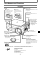
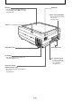
Part Names and Functions Part Names and Functions Projector Handle Materials Cover ■ Extended ■ Retracted Press lightly on the left side of the handle and it rotates 180˚ and comes out. Rotate the handle while pressing on its right side to store it. The scanner and printed matter is located under this cover. See page E-31. Operation panel Buttons for operating the projector are located here. See page E-12.
Scanner Speakers Place documents or printed matter here to project images when OHP is selected. See page E-31 Power (Cord connecter) Connect the power cord into this terminal. See page E-20. Sensor Adjustable Feet Adjustable Feet Air Vent B Air is discharged from the inside to the outside through this vent. I/O Terminal Panel Connection terminals for a PC or video source are located here. See page E-11. Lamp Unit Cover (bottom of main unit) The scanner lamp unit is housed inside this cover.
Part Names and Functions ■ Terminal Panel q w RGB-IN 2 r RGB-OUT TEST V R PC AUDIO IN2 RGB-IN 1 PC AUDIO PC AUDIO IN1 OUT S-VIDEO t e y u L VIDEO i q PC Video Input Input terminal for the PC analog RGB signals. Two personal computers can be connected. w PC Audio Input Audio input terminal for a PC (stereo compatible). Two personal computers can be connected. When OHP is selected, OHP images are output. When PC/VIDEO input is selected, input PC video is output as it is.
■ Buttons and Indicator Lights q w e r POWER ON/ STANDBY LAMP/ COVER t OHP PC1/PC2 SCROLL VIDEO TEMP KEYSTONE y Name q POWER Button w TEMP LED e LAMP/COVER LED r ON/STANDBY LED t INPUT SELECT Buttons (OHP, PC1/PC2, VIDEO) y KEYSTONE Button u MUTE Button i BRIGHTNESS Buttons MUTE u BRIGHTNESS ZOOM MENU i o !0 !1 Description • Press this button to turn the lamp on or off. • Only this button can be used when the lamp is off.
Part Names and Functions o ZOOM Buttons • These buttons adjust the zoom ratio. Pressing the button reduces the image, and pressing the button enlarges the image. • Display the menu display. • Set and select the variable and adjustable values on the menu display. • Move the zoom position when using the zoom display. • Move the pointer when the pointer is displayed.
■ Buttons and Indicator Lights !2 !3 !4 POSITION RESIZE ROTATION V LIVE IMAGE H REFRESH SET OHP STORED IMAGE POINTER VOLUME !5 Name !2 RESIZE Button !3 POSITION Buttons FREEZE !6 !7 Description Page to see • Press to change the size of the projected image when OHP E-33 is selected. • Press to do automatic synchronous adjustments when PC E-38 is selected. E-31 • Press to change the orientation of the projected image when OHP is selected.
Part Names and Functions Remote Controller q POWER MUTE MENU POINTER TYPE REFRESH w t y u FREEZE e, r POINTER/ SET ZOOM i RESIZE OHP o !0 Name q POWER Button w POINTER TYPE Button e POINTER/SET Button • • • • • r SCROLL Button • t MUTE Button • • • y MENU Button • u REFRESH/FREEZE Button • • i RESIZE Button • • o INPUT SELECT Buttons (OHP, PC1/PC2, VIDEO) • • !0 P in P Button • POSITION ROTATION V !1 H BRIGHTNESS PC1/PC2 VOLUME VIDEO OHP STORED IMAGE P in P LIVE IMAGE
!1 ZOOM Buttons !2 POSITION Buttons • These buttons adjust the zoom ratio. Pressing the button reduces the image, and pressing the button enlarges the image. • Press to change the orientation of the projected image when OHP is selected. Press the button to reverse the top and bottom of the projected image. Press the button to switch between vertical display and horizontal display. • These buttons adjust the brightness.
Part Names and Functions ■ Remote Control Operations • Use the remote control within about seven meters (7.7 yards) from the remote control sensors (on the front and rear sides) of the projector and within 10 degrees to the left and right. This distance may become shorter as the battery wears down. • The remote controller does not work if there are obstacles between the remote control and the remote sensor on the main unit. ■ Battery Replacement 1.
How to Install the Projector ■ Installation Sequence Check the installation site and image size. Prepare the screen. Install the input devices. Install the projector. End PC, video source, etc. See “Projection Distance and Projected Image Size” on page E-19. ■ Adjusting the Tilt The position and tilt angle of the projected image can be adjusted by adjusting the adjustable feet.
How to Install the Projector ■ Projection Distance and Projected Image Size Use the following diagrams to determine the projected image size and the type of screen required for any given projector location. • The projection distance that provides good focusing is 1.4 m (1.5 yd) to 13.9 m (15.2 yd) from the front of the lens. Install the projector within this range. Vertical Dimension Horizontal Dimension Projected Image Size Projected Image Size Projection Distance (1.43 m to 13.9 m/1.5 yd to 15.
■ Typical Installation ;; ;; ;; ;; ;; ;; 1. Select the installation site Place the projector on an even and stable surface such as a table. POWER 2. Connect the power cord (supplied), and press the button.) button (or POWER ;;; ;;; ;;; ;;; ;;; ;;; 90° 3. Turn the direction of the lens so that it is perpendicular to the screen. Turn the unit to the left or right so that the top and bottom lines of the projected image are parallel. ;;; ;;; ;;; ;;; ;;; ;;; Adjustable feet 4.
How to Install the Projector ■ Compensating Keystone If the projected image is distorted, you can eliminate the distortion by doing keystone compensation. ● How to Compensate Keystone KEYSTONE Keystone KEYSTONE Press the button (or the button on the remote controller) to display the “Keystone menu.” Hor izontal 0 Ver tical 0 MENU SET Set standard Quit u Keystone menu Press the button to make the top of the projected image narrower.
Connecting to a Personal Computer CAUTION Cautions on Connection • Before connecting other devices, turn off each device to protect the projector and other connected devices. • For details of how to connect and use devices connected to the projector, refer to the User’s Manual for each device. • Sometimes images are not displayed on the screen properly when they are displayed on a notebook PC LCD as well. If this happens, turn the notebook PC display off to remedy this.
Connecting to a Personal Computer About the PC Input and Output The 15-pin mini D-Sub connectors are used for the PC input and output terminals. The following shows the relationship between the pins and the input and output signals. 5 4 10 15 3 9 14 2 8 13 7 12 q RED VIDEO w GREEN VIDEO e BLUE VIDEO r GND t NC 1 6 11 y GND u GND i GND o NC !0 GND !1 !2 !3 !4 !5 NC Pull up (+5V) H.SYNC V.SYNC Pull up (+5V) NOTE • This projector uses a 15-pin RGB input and an analog type output terminals.
■ When Images on the Personal Computer Screen are not Projected Check the following when images on the personal computer screen are not projected or projected images are incorrect. ● When images are not projected When external output signals are input to the MP-50E from the PC, “No signal” is displayed on the screen. When this is displayed, check the following. 1 Try restarting the personal computer. The MP-50E is sometimes not recognized by the PC if it is connected after the PC is started up.
Connecting to a Personal Computer ■ Input Signal Compatibility Table (PC video input terminal) The MP-50E supports the signals marked by ● in the following table. Note that on some PC models, flickering and blurring occur in the projected image. If this happens, adjust the projected image in the Sync Adjustment menu. Signal Name NTSC RGB Resolution (Horizontal ✕ Vertical) - Horizontal Frequency Vertical Frequency (kHz) (Hz) 15.7 60 Compatibility ✕ - - 15.6 50 ✕ VGA-GR1 640 480 31.
● Basic connections To RGB output connector on PC To analog RGB connector on monitor The connector cable model No. differs according to the type of PC. To audio output terminal on PC Fix the connector cable using the screw-in fasteners. To speaker input terminals Terminal panel on the back of the MP-50E main unit NOTE • The personal computer has input terminals for both image and sound for “1” and “2”. Hook up the sound and image to the corresponding terminals.
Connecting to a Personal Computer ● Connecting to an IBM Desktop and Compatible Cable supplied with monitor To RGB-OUT terminal To RGB-IN1 or RGB-IN2 terminal Signal Cable (supplied) MP-50E NOTE When connecting the projector directly to the PC without using the monitor supplied with the PC, you can connect by the supplied cable only.
■ Connecting to a Video Source or DVD Player Images from a video source or DVD player can be projected on a large screen. V L VIDEO R Terminal panel on the back of the MP-50E main unit To Audio Output Terminal To Video Output Terminal Or DVD Player Video Source NOTE • When both VIDEO and S-VIDEO are connected, S-VIDEO is given higher display priority. • Before using the video source or DVD player, close the materials cover.
Basic Operation Basic Operation ■ Preparation 2 1 1 1 Connect the power cord. ON/ STANDBY LAMP/ COVER TEMP The projector is in the standby mode, and the power indicator LED lights (red). Press the POWER button. The fan spins, the LED lights, and the ON/STANDBY LED lights (green). The LAMP/COVER LED lights (green). If the LAMP/COVER LED lights red after turning on the POWER button, then there is something wrong. (See page E52 for details.
■ Basic Operations in the OHP Mode 5 2 3,6,7,8,9,10, 11,12,13,14, 15,17 1 NOTE The projected image in the OHP display (projection of actual object) may be slightly distorted as a very wideangle lens is used. 1 Adjust the size of the projected image. Rotate the zoom adjuster on the projection lens to adjust the size of the projected image. 2 Adjust the focus. Adjust the focus adjuster on the projection lens until the projected image is sharp. 3 Main Unit Operation Compensate the keystone.
Basic Operation 5 Set the object you want to project. Open the materials cover, and place the document or printed matter you want to project on the scanner. A video image of the projected material appears in the window. Close the materials cover. NOTE Objects can be projected even if the materials cover is not closed. However, unwanted objects will also be picked up, making the projected image difficult to view. 6 Main Unit Operation Adjust the brightness.
8 Main Unit Operation REFRESH Freeze the projected image. Press the REFRESH/FREEZE button to project a frozen image, of the material that you set in step five, on the white area of the projected image. FREEZE Remote Control Operation REFRESH FREEZE 9 Main Unit Operation Close the window. Press the LIVE IMAGE button to close the window that is displayed, the entire projected image freezes. LIVE IMAGE Remote Control Operation LIVE IMAGE 10 Main Unit Operation Adjust the zoom ratio.
Basic Operation 12 Main Unit Operation RESIZE Project a full-screen image. When projecting a vertical image, press the RESIZE button to switch between a projected image that fills the screen from side to side or to one that fills the screen from top to bottom. (You can switch them even when adjusting the zoom.
15 Main Unit Operation SET Display the pointer. Press the SET/POINTER button to display the pointer. Press it again to hide the pointer. Press the SCROLL button to move the pointer. POINTER Remote Control Operation POINTER/ SET NOTE Adjusting the zoom or the brightness while the pointer is displayed may cause it to disappear momentarily, but it will reappear after a short time.
Basic Operation Document Orientation and Scan Size Place the document or printed matter face down at the orientation shown in the figure below. The maximum size that documents or printed matter can be scanned is 216 mm/8.5 in (vertical) and 288 mm/11.3 in (horizontal). For this reason, the projected sizes are as follows when an A4-size sheet of paper is placed at the respective orientations. (Shaded section is the projected area.) A4 horizontal orientation 297 mm/11.6 in (paper size) 210 mm/8.
Displaying OHP stored image OHP STORED IMAGE Pressing the buttons display and switch the stored images in the internal memory. button: Displays the image previous to the stored image that is currently displayed. button: Displays the image following the stored image that is currently displayed. * Pressing the button while a stored image is not displayed causes the most recently refreshed image that was stored to be displayed.
Basic Operation ■ Basic Operation of PC or Video Input 3,4,5,6,7, 8,10,11,13 2 1 1 Adjust the size of the projected image. Rotate the zoom adjuster on the projection lens to adjust the size of the projected image. 2 Adjust the focus. Adjust the focus adjuster on the projection lens until the projected image is sharp. 3 Main Unit Operation Compensate keystone. See “Compensating Keystone” on page E-21. KEYSTONE Remote Control Operation KEYSTONE 4 Main Unit Operation Adjust the brightness.
5 Main Unit Operation Adjust the zoom ratio. You can adjust the zoom between 1x to 4x. Pressing the button (or the button on the remote controller) reduces the image, and pressing the button (or the button on the remote controller) enlarges the image. ZOOM ZOOM ZOOM Remote Control Operation ZOOM 6 Main Unit Operation SCROLL Move the zooming position. Press the arrow buttons on the remote controller to move the zooming position of the image. You can move in eight directions.
Basic Operation 9 Remote Control Operation POINTER TYPE 10 Main Unit Operation OHP STORED IMAGE Select the type of pointer. You can switch the type of pointer with the POINTER TYPE button on the remote controller. (Select from , , or .) You can also select the type from “Pointer type” on the “Setting 2” menu. See page E-45 for details. Adjust the volume. OHP STORED IMAGE Press the Press the VOLUME OHP STORED IMAGE VOLUME button to reduce the volume. button to increase the volume.
12 Remote Control Operation P in P Display images from the personal computer and the video at the same time. If you select personal computer input while a video source and a personal computer are both connected, you can display video images in the window at the lower right side of the projected image. Set “Picture in Picture” to “ON” on the quick menu to display video images. See page E-51 for details. NOTE • The P in P button is only enabled when a personal computer is selected.
Basic Operation ■ How to Quit 1 2 1 Main Unit Operation Turn the lamp off. Press the POWER button. (Hold down for at least one second.) POWER Remote Control Operation “Press POWER button again to turn off.” is displayed on the projected image. POWER Press the POWER button again. The LAMP/COVER LED blinks green, and then goes out after about one minute. The ON/STANDBY LED lights (red.) NOTE The lamp will not turn on even if you press the POWER button if the LAMP/COVER LED is blinking green.
■ Performing Various Adjustments Menu Structure You can perform various adjustments and make various settings by operating the buttons with the menu display displayed on the projected image. There are two menus, the “Quick menu” on which there are frequently used items, and the “Main menu” on which more detailed settings can be done. When a personal computer or video is connected and the power is on, you can open the “Quick menu” by pressing the button (or the button on the remote controller.
Basic Operation Description of Menu Items The following describes each of the menu displays, and the items and functions that can be set in these menu displays. For details of how to set these menu items, see “Basic Operation” on page E-47. ◆ Image Adjustment (when PC input is selected) Image adjustment Contrast 0 Brightness 0 Red 0 Blue 0 Contrast Brightness 1 Sharpness Menu Item 2 3 4 5 Setting Item Description -100 ~ +100 Adjusts the contrast of the projected image.
◆ Image Adjustment (when OHP is selected) Image adjustment Red 0 Blue 0 Standard / Natural Image mode PHOTO / TEXT Gamma Standard Menu Item Setting Item Description Red Blue Image mode -100 ~ +100 -100 ~ +100 Standard/ Natural Adjusts the depth of the color red. Adjusts the depth of the color blue. If you want to display an image that has high contrast and sharpness select “Standard”; if you want to reproduce colors that are close to the original select “Natural.
Basic Operation ◆ Setting 1 Setting 1 Lamp usage time Input signal 24H 1024 x 768 / 48.6KHz 60Hz Menu Item Setting Item Description Auto power off ON/OFF Start-up display ON/OFF Economy mode ON/OFF Sets the auto power off function ON/ OFF. When auto power off is set to ON, the projector automatically goes to standby mode if no signals are input for a fixed period of time (about 15 minutes). Sets whether or not to display the Logo while the lamp is on. Sets the lamp in Economy mode.
◆ Language Selection Language selection Menu Item English Española Deutsch Svenska Français Language selection Italiano Return Setting Item Description English Sets the language used in display. Deutsch Français Italiano Española Svenska ◆ Projection Mode Projection mode Menu Item Front Projection mode Rear Setting Item Front Rear Description Adjusts the projection mode according to the installation method (front (standard) projection or rear projection).
Basic Operation ■ Basic Operation The following describes basic operations in the following menus: “Image Adjustment”, “Sync Adjustment”, “Setting”, “Language Selection”, “Video Adjustment”, and “Projection Mode” . 1 Main Unit Operation MENU MENU Press the button (or the remote controller). button on the The main menu is displayed.
3 Main Unit Operation SET Press the button (or the remote controller). POINTER/ SET button on the POINTER The menu for the item you want to set is displayed. To return to the initial settings when you bought the projector, select “Standard” and press the button (or button) in the “Image adjustment”, “Sync adjustment”, “Setting” or “Video adjustment” menus.
Basic Operation 4-2 Main Unit Operation Press the “OFF”. buttons to select “ON” or Setting 1 Lamp usage time 24H Input signal SCROLL RESIZE 1024 x 768 / 48.
4-2 Press the buttons to adjust the setting. Main Unit Operation Sync adjustment SCROLL RESIZE Clock 0 Phase 0 Horizontal 0 Vertical 0 SET MENU Standard Return POINTER 4-1, 5 4-2 5 Others Other menu items include “Language selection”, “Projection mode” and “Video select”. For details of menu items, see page E-46. Remote Control Operation POWER MUTE 4-1 MENU POINTER TYPE REFRESH Press the buttons to select the item you want to set.
Basic Operation ■ Quick Menu The Quick menu has frequently used items. This section describes the items and functions that can be set on the Quick menu. Press the button (or the button on the remote controller) to display the quick menu.
Maintenance ■ Fault Protection Your projector is provided with internal protection circuits for preventing fire and damage to internal components due to abnormal temperature. ● When the LAMP/COVER LED is blinking: ❍ Action 1. Disconnect the power plug from the power outlet. 2. Correctly install the air filter. For details, see “Cleaning the Air Filter” on page E-56. 3. Correctly install the lamp unit cover. For details, see “Lamp Unit Replacement” on page E-54.
Maintenance ● When the power fails (all LEDs are off when the power is turned ON) ❍ Action 1.Disconnect the power plug from the power outlet. 2.Check the following and take corrective actions. Is the ambient temperature more than 35°C (95°F)? Are any vent holes blocked? A probable cause is an internal circuit problem. Use your projector within an ambient temperature of 0°C to 35°C (32°F to 95°F). Place your projector away from walls and other objects. See “Do not block the air vents” on page E-4.
■ Lamp Unit Replacement The target replacement time of the lamp used on this projector is 1400 hours. (This may be shortened depending on the conditions of use.) Since there is a high possibility of lamp explosion if the cumulative usage time exceeds more than 1500 hours, the power to the lamp is cut off at 1500 hours.In the following instances where the cumulative usage time of the lamp is more than 1400 hours, replace the lamp unit (sold separately).
2 Maintenance Loosen the lamp unit retaining screws. Loosen the lamp unit screws. (2 pieces) 3 Draw out the lamp unit. Hold the handle and lift the lamp unit upward. 4 Install a new lamp unit. q Hold the lamp unit and push it in. w Make sure that the two positioning protrusions fit properly into the holes. e Tighten the two lamp unit retaining screws. r Align the three tabs on the lamp unit cover with the slots on the projector to attach it. Then tighten the two lamp unit cover retaining screws.
■ Cleaning the Air Filter The air filter is an important part as it keeps the optical components inside your projector free from dirt and dust. A clogged air filter can cause the temperature to rise inside your projector and the fan speed to increase. This, in turn, may reduce lamp life or cause the projector to malfunction. The air filter should be cleaned regularly (about once a month if the projector is used four hours a day).
Troubleshooting Troubleshooting If you think a problem has occurred, check the following items before asking for a repair. To be Checked Symptom Power is not on. • Verify that the power cord is connected. The projection lamp does not light. • Verify that the lamp has not blown. Page(s) E-20 E-54 • Verify that the lamp unit cover is installed. E-54 • Verify that the air filter is installed. E-56 • Verify the internal temperature.
Repair Service Repair Service Procedure • Before asking for repair service, check the Troubleshooting section on page E-57 once more. If this check confirms a problem, contact the dealer where you bought the product. • When asking for repair service, provide your dealer with the following information: Description of the problem (as many details as possible) Date of purchase Your Name Your Address Telephone number Product name and model No.
Troubleshooting Specifications Specifications MP-50E Model Name Type Audio input/output Video Input/Output Main Part Specification 3 primary Color LCD Shutter Projection Type 1.0 inches x 3 Panels, Aspect Ratio 4:3 LCD Panel Size Poly Silicon TFT Active Matrix with Micro Lens Array Drive System Number of Pixels 786,432 pixels (1,024 x 768 dots)⳯3 Stripe Arrangement Manual Zoom: 1 to 1.25x, f=36.5 mm to 45.6 mm, F1.7 to 2.