Service Source PowerBook G4 (12-inch 1.33 GHz) Updated October 25, 2005 © 2004 Apple Computer, Inc. All rights reserved.
Service Source Take Apart PowerBook G4 (12-inch 1.33 GHz) © 2004 Apple Computer, Inc. All rights reserved.
General Information Overview Some of the key features that distinguish this computer from earlier notebook models include: • Faster processor at 1.33 GHz • Cable guides on frame • Latches in battery bay to secure top case General Information PowerBook G4 (12-inch 1.
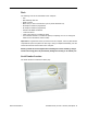
Model Differences The external housing of the PowerBook G4 (12-inch 1.33 GHz) model looks the same as the PowerBook G4 (12-inch DVI) model. Both have a mini-DVI port (shown below). The mini-DVI port is used with an adapter cable to connect the computer to a monitor, television, VCR, or other video device. The adapter cables that can be used with this port include a mini-DVI-to-DVI adapter, a mini-DVI-to-VGA adapter, and a mini-DVI-to-S-Video adapter. To distinguish the PowerBook G4 (12-inch 1.
Tools The following tools are recommended for this computer: • Coin • ESD wriststrap and mat • Small soft cloth • Black stick (or other nonconductive nylon or plastic flat-blade tool) • #0 Phillips screwdriver (magnetized) • #1 Phillips screwdriver (magnetized) • Jeweler’s flat-blade screwdriver • 1.
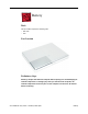
Battery Tools This procedure requires the following tools: • Soft cloth • Coin Part Location Preliminary Steps Warning: Always shut down the computer before opening it to avoid damaging its internal components or causing injury. After you shut down the computer, the internal components can be very hot. Let the computer cool down for 30 minutes before continuing. 4 - PowerBook G4 (12-inch 1.
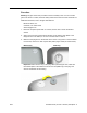
Procedure Warning: If the computer has been recently operating, allow it to cool down before performing this procedure. 1. Shut down the computer. 2. Unplug the power adapter, phone cord, and any other cables connected to the computer. 3. Turn over the computer and place it on a soft cloth. 4. Use a coin to release the battery lock. 5. Lift the battery out of the battery bay. 6. Install the replacement battery, and reassemble and test the computer. Battery PowerBook G4 (12-inch 1.
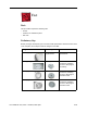
Feet Tools This procedure requires the following tools: • Foot kit • Tweezers or needlenose pliers • Soft cloth Preliminary Step Before you begin, identify the type of foot that needs replacement. Check the bottom case of the computer, and compare it with the images in this table: Plug Area on Bottom Case Matching Foot Action Missing plug Not available for replacement Do not perform the foot replacement.
Procedure Warning: The glue used in this procedure can bond instantly to skin. Do not touch the glue. In the event of contact, review the safety instructions at the end of this document. For additional information, refer to the glue manufacturer: Elmer's Products, Inc. Columbus, OH. 43215-3799 www.krazyglue.com 1. Place the computer upside down on a clean, lint-free cloth or other nonabrasive surface. 2. Select a foot from the kit that matches the plug on the bottom case.
4. Warning: GLUE IS AN EYE AND SKIN IRRITANT. BONDS SKIN INSTANTLY. Do not touch the glue at any time. Before opening the glue, review the safety instructions at the end of this document. Important: The glue tube included in the kit is sealed until first use. Do not break the seal until you are ready to use the glue. To break the seal, hold the tube upright and away from you. Place the hollow nozzle cap on the tube and tighten it all the way down.
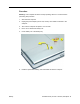
Memory Door and Memory Card Tools This procedure requires the following tools: • Soft cloth • #0 Phillips screwdriver • Black stick (or other nonconductive nylon or plastic flat-blade tool) Part Location Preliminary Steps Before you begin, remove the battery. Procedure Warning: If the computer has been recently operating, allow it to cool down before performing this procedure. Memory Door and Memory Card PowerBook G4 (12-inch 1.
1. Place the computer upside down on a soft cloth. 2. Remove the four identical screws from the memory door. 3. Use a black stick to lift off the memory door. 4. Touch a metal surface inside the computer to discharge static electricity from your body. 5. If a memory card is already installed, release it by spreading apart the tabs in the expansion slot from the notches in the card. Allow the card to pop up slightly, and pull it out of the memory slot. 10 - PowerBook G4 (12-inch 1.
6. Insert the replacement memory card into the expansion slot at a 30-degree angle. 7. Make sure the memory card is fully inserted. Check that the notches in the card clear the tabs as you press down on the sides of the card to lock it into place. 8. Install the memory door. Be careful not to overtighten the screws. 9. Install the battery, and test the computer. Memory Door and Memory Card PowerBook G4 (12-inch 1.
AirPort Extreme Card Tools This procedure requires a black stick (or other nonconductive nylon or plastic flat-blade tool). Part Location Preliminary Steps Before you begin, remove the battery. 12 - PowerBook G4 (12-inch 1.
Procedure Warning: If the computer has been recently operating, allow it to cool down for 30 minutes before performing this procedure. 1. Touch a metal surface inside the battery bay to discharge static electricity from your body. 2. Open the door to the AirPort slot. 3. If an optional AirPort Extreme Card is already installed, use a black stick to un-loop the pull tab. AirPort Extreme Card PowerBook G4 (12-inch 1.
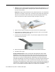
4. Gently disconnect the AirPort antenna cable. 5. Use the pull tab to pull out the card. 14 - PowerBook G4 (12-inch 1.
6. Slide the replacement AirPort Extreme Card with the serial number facing up into the slot, as shown. AirPort Extreme Card PowerBook G4 (12-inch 1.
7. Connect the end of the antenna cable to the card. 8. Loop the clear plastic tab under the card so that the tab secures the antenna cable and tucks into the slot. Note: The AirPort slot on the bottom case has a recessed inner slot designed for the clear plastic tab to tuck into. 9. Close the AirPort door, and reassemble and test the computer. 16 - PowerBook G4 (12-inch 1.
Keyboard Tools This procedure requires the following tools: • #0 Phillips screwdriver • Black stick (or other nonconductive nylon or plastic flat-blade tool) Note: To organize the screws you remove from the computer, use a tray with divided compartments (such as a plastic ice cube tray). Part Location Preliminary Steps Before you begin, remove the following: • Battery • Memory door and memory card Keyboard PowerBook G4 (12-inch 1.
Procedure 1. With the computer upside down on a soft cloth, remove the single screw and small EMI shield from the memory card bay. Replacement Note: Make sure you replace the screw and EMI shield so that the EMI shield is positioned with the finger-like projection pointing up. 18 - PowerBook G4 (12-inch 1.
2. Open the computer, and locate the following keys: • F1 • F2 • F11 • F12 3. Important: Using a black stick, carefully pry up each of the four keys from the left side of each key. The keys are easily removed from the left side without damaging the keyboard. Keyboard PowerBook G4 (12-inch 1.
4. Use a black stick or flat-blade screwdriver to lift off the two round stickers that are located between the two key mechanisms. Reserve the stickers for replacement. 5. Remove the screw under each of the stickers. 20 - PowerBook G4 (12-inch 1.
6. Lift up the top two corners of the keyboard, and move the keyboard toward the display to clear the tabs at the bottom of the keyboard. Keyboard PowerBook G4 (12-inch 1.
7. Flip the keyboard over and lay the keyboard flat on the trackpad. 8. Peel up the keyboard cable from its adhesive. Using a black stick, pry up the tabs at the ends of the connector, and then pull the cable straight up to disconnect it. 22 - PowerBook G4 (12-inch 1.
9. Install the replacement keyboard. Make sure you • Set the tabs at the bottom of the keyboard into the slots in the top case. • Press the keyboard into place, and install the screws and round stickers. • Install the function keys: – Position the key directly over the scissor mechanism. – Press the key onto the scissor. – Check the operation of the key. • Close the display and install the final screw in the memory bay. 10. Reassemble and test the computer. Keyboard PowerBook G4 (12-inch 1.
Top Case Tools This procedure requires the following tools: • #0 Phillips screwdriver • Black stick (or other nonconductive nylon or plastic flat-blade tool) • Hex 1.5 mm screwdriver Note: To organize the screws you remove from the computer, use a tray with divided compartments (such as a plastic ice cube tray). Part Location Preliminary Steps Before you begin, remove the following: • Battery • Memory door and memory card • Keyboard 24 - PowerBook G4 (12-inch 1.
Procedure 1. Warning: The screws in the battery bay require holding the screwdriver at an angle. Be careful not to strip the screws. Note: Avoid scratching the external housing by using care when removing the screws. You might want to cover part of the housing with a soft cloth as you remove screws. With the computer upside down on a soft cloth, remove the three screws from the bottom case at the battery bay. 2. Remove the screws near the display hinge. Top Case PowerBook G4 (12-inch 1.
3. Open the display, and with the computer upright, remove the following 14 screws from the top case: • one Hex, 16.5-mm long screw at upper right corner near power button • one Hex, 7-mm long screw at upper left corner near microphone • one #0 Phillips, 14.5-mm long screw in keyboard well • five #0 Phillips, 4.5-mm long screws in keyboard well • six #0 Phillips, 2.5-mm long screws in keyboard well Replacement Note: When replacing the top case screws, install the screws in the order shown.
4. Remove two screws from the front right side of the top case. Note: The shape of the two 3-mm long screws differs from most of the screws used in the computer. The screw has a collar under the screw head. Replacement Note: In addition to securing the top case to the bottom case, the two 3-mm long screws help secure an inner bracket to the battery well. Make sure the bracket and two latches are installed in the bottom case before replacing the top case. 5.
6. Place the computer on its side, and loosen but do not remove the half of the top case that is closest to the display. 28 - PowerBook G4 (12-inch 1.
7. At the battery bay, note the two plastic latches that hold the top case to the bottom case. 8. Use a black stick to release both latches. Top Case PowerBook G4 (12-inch 1.
9. Use a black stick running along the front edge of the top case to loosen—but not remove—the top case from the bottom case. 10. In the keyboard well, pull up the looped end of the trackpad cable to disconnect it. 30 - PowerBook G4 (12-inch 1.
11. Raise the top case up slightly from the bottom case until you can access the cables that are connected under the top case. 12. Important: Do not forcefully remove the top case. With the cables still connected, carefully move the top case aside to disconnect the microphone cable and power cable. 13. Remove the top case from the computer. Top Case PowerBook G4 (12-inch 1.
14. The top case includes the following: • Microphone cable • Trackpad and trackpad cable • Power button and cable • Tape • Welded EMI strips • Magnet in keyboard well • Foam spacers 32 - PowerBook G4 (12-inch 1.
15. Before installing a replacement top case, check the cable routing of the • Power button cable • Microphone cable • Trackpad cable Make sure the cables are routed correctly and cannot be pinched when installing the top case. 16. Install the replacement top case, and reassemble and test the computer. Top Case PowerBook G4 (12-inch 1.
Hall Effect Sensor Board and Cable Tools This procedure requires the following tools: • Phillips #0 screwdriver • Black stick (or other nonconductive nylon or plastic flat-blade tool) Part Location Preliminary Steps Before you begin, remove the following: • Battery • Memory door and memory card • Keyboard • Top case 34 - PowerBook G4 (12-inch 1.
Procedure 1. Remove the screw from the hall effect sensor board. Warning: When replacing the board, make sure you use the same screw. A longer screw could scratch the optical media. 2. Tilt up the board, and free the cable from the cable routing guides along the lower edge of the optical drive. 3. Lift up the tape, if provided, from the corner of the optical drive. 4. Disconnect the 3-pin connector from CN4 at the DC-to-DC board. 5. Install the replacement board, and reassemble and test the computer.
Replacement Note: Make sure the cable is routed correctly in the cable guides along the lower edge of the optical drive. 36 - PowerBook G4 (12-inch 1.
Hard Drive Tools This procedure requires the following tools: • #0 Phillips screwdriver • Black stick (or other nonconductive nylon or plastic flat-blade tool) Note: To organize the screws you remove from the computer, use a tray with divided compartments (such as a plastic ice cube tray). Part Location Preliminary Steps Before you begin, remove the following: • Battery • Memory door and memory card Hard Drive PowerBook G4 (12-inch 1.
• Keyboard • Top case Procedure 1. Disconnect the hard drive flex cable. 2. Remove two screws from the hard drive bracket. 38 - PowerBook G4 (12-inch 1.
3. Use the flex cable to lift up the hard drive, bracket, and cable from the computer housing. 4. Turn over the hard drive and remove the two screws from the underside of the drive. Hard Drive PowerBook G4 (12-inch 1.
5. Peel up the flex cable from its double-sided tape. 6. Use a black stick to pry the flex cable connector up slightly on each side, and then pull it straight off the drive. Be careful not to bend any pins. 7. Remove the two screws and grommets from the opposite side of the drive. 8. Replacement Note: When installing the replacement drive, make sure the center flange of the hard drive bracket fits over the small post on the computer frame. 9.
Modem Tools This procedure requires the following tools: • #0 Phillips screwdriver • Black stick (or other nonconductive nylon or plastic flat-blade tool) Part Location Preliminary Steps Before you begin, remove the following: • Battery • Memory door and memory card • Keyboard • Top case Modem PowerBook G4 (12-inch 1.
Procedure 1. Warning: When removing the modem, be careful not to strain the modem cable or shield. Do not apply pressure to the modem. Read all of the procedure before removing and replacing the modem. 2. Remove the three identical screws from the modem board and shield. 3. Use a black stick to tilt up the modem and disconnect it from the logic board. 42 - PowerBook G4 (12-inch 1.
4. Tilt up the modem board and shield. 5. Disconnect the modem cable. Modem PowerBook G4 (12-inch 1.
6. Install the replacement modem, and reassemble and test the computer. Replacement Caution: When placing the replacement modem on the logic board, be sure to align the board and shield over the modem connector on the logic board. Handle the modem by the edges only. When securing the modem to the logic board, press only on the rectangular area (highlighted in green in the following image) that is directly over the modem connector. 44 - PowerBook G4 (12-inch 1.
DC-to-DC Board Tools This procedure requires the following tools: • #0 Phillips screwdriver (magnetized preferred) • Black stick (or other nonconductive nylon or plastic flat-blade tool) • 4 mm socket wrench or needlenose pliers Note: To organize the screws you remove from the computer, use a tray with divided compartments (such as a plastic ice cube tray). Part Location DC-to-DC Board PowerBook G4 (12-inch 1.
Preliminary Steps Before you begin, remove the following: • Battery • Memory door and memory card • Keyboard • Top case • Hard drive Procedure 1. Disconnect the sleep light cable and the hall effect sensor board cable from the DC-toDC board. 46 - PowerBook G4 (12-inch 1.
2. Remove the screws from the DC-to-DC board. Note: When removing the 4.5-mm long screw, the magnetic latch might draw the screw toward it. The 13.5-mm long screw has a hex head and requires a needlenose pliers or socket wrench to remove it. Replacement Note: When replacing the DC-to-DC board, install the screws in the order shown. 3. Lift off the EMI strip from the battery connector. Be sure to replace it when installing the replacement DC-to-DC board. DC-to-DC Board PowerBook G4 (12-inch 1.
4. Place a black stick just under the top edge of the board. Do not lean the black stick on the modem board or optical drive. Disconnect the DC-to-DC board from the logic board by prying up the DC-to-DC board and removing it from the computer assembly. 5. Install the replacement DC-to-DC board, and reassemble and test the computer. 48 - PowerBook G4 (12-inch 1.
Heatsink and Fan Assembly Tools This procedure requires the following tools: • #0 Phillips screwdriver • #1 Phillips screwdriver • Black stick (or other nonconductive nylon or plastic flat-blade tool) Note: To organize the screws you remove from the computer, use a tray with divided compartments (such as a plastic ice cube tray).
Procedure 1. Warning: The cone of the subwoofer, located below the heatsink and to the right of the fan, is a sensitive device. Avoid touching the subwoofer cone as you perform this procedure. 2. If tape covers any of the following screws, peel up the tape. Remove the following screws from the heatsink: • Three 6-mm long #0 Phillips screws • Two 7.5-mm long #1 Phillips screws with springs • One 12.5-mm long #0 Phillips screw • One 4.5-mm long #0 Phillips screw 50 - PowerBook G4 (12-inch 1.
3. Remove the tape, if provided, that covers the heatsink and secures the cables in place. 4. Near the fan, peel up the tape and remove the following screws: • One 3-mm long screw • One 12-mm long screw Replacement Note: When reapplying tape around the fan, make sure the fan blades are not blocked. The image below shows the correct application of tape. 5. Disconnect the inverter cable that runs along the top of the fan.
7. Holding the heatsink plate, begin to lift up the heatsink assembly, being careful where it catches on remaining tape and the chassis. Use a black stick to pry up the middle right corner of the heatsink plate. Warning: To avoid bending the heatsink, support the heatsink as it is removed. 8. Note the placement of the thermal pads. Make sure you replace the thermal pads whenever the heatsink is removed or replaced. 52 - PowerBook G4 (12-inch 1.
9. Note the correct routing of the cables when the heatsink is installed. . 10. Install the replacement heatsink, and reassemble and test the computer. Heatsink and Fan Assembly PowerBook G4 (12-inch 1.
Inner Frame Tools This procedure requires the following tools: • #0 Phillips screwdriver • Black stick (or other nonconductive nylon or plastic flat-blade tool) Note: To organize the screws you remove from the computer, use a tray with divided compartments (such as a plastic ice cube tray). Part Location Preliminary Steps Before you begin, remove the following: • Battery • Memory door and memory card • Keyboard • Top case 54 - PowerBook G4 (12-inch 1.
• • • • Hard drive Modem DC-to-DC board Heatsink Procedure 1. Note the cable routing before disconnecting cables. Replacement Note: Reserve any tape for securing cables after the frame replacement. 2. Warning: The subwoofer cone, located below the right corner of the frame, is a sensitive device. Avoid touching the cone as you perform this procedure. 3. Disconnect the connector from the upper right corner of the logic board. Inner Frame PowerBook G4 (12-inch 1.
4. Warning: Be careful not to strain the LVDS cable. Near the I/O ports, • disconnect the LVDS cable by using the pull-tab on the connector • disconnect the 6-pin connector Replacement Note: When reinstalling the LVDS cable, tuck the pull-tab under the frame. 5. Remove the screw that secures the LVDS cable to the frame. 56 - PowerBook G4 (12-inch 1.
6. Near the fan, disconnect the two connectors shown • four-pin connector • two-pin connector Replacement Warning: When reassembling the computer, notice the two black insulated cables that run along the bottom of the fan. To avoid damaging the cables, make sure that the thinner twisted cable is routed on top of the thicker fan cable and that both cables are routed between the fan and the modem standoff, as shown. Inner Frame PowerBook G4 (12-inch 1.
7. Peel up any remaining tape, and remove the screws from the frame and I/O port shield. 58 - PowerBook G4 (12-inch 1.
8. Remove the 6-mm long screw at the RJ11 board. 9. Disconnect the optical drive flex cable. 10. Pull up the hall effect sensor cable from a few of the cable routing guides only until it clears the frame. Inner Frame PowerBook G4 (12-inch 1.
11. Lift up the frame, being careful where it catches on the optical drive flex cable and other cables. 60 - PowerBook G4 (12-inch 1.
Replacement Note: When installing the replacement frame, note the routing of the cables through the frame channels. Inner Frame PowerBook G4 (12-inch 1.
12. Remove the tape that secures the RJ11 board and cable to both sides of the frame. Transfer the RJ11 board and cable to the replacement frame. 13. Remove the screws that secure the EMI strip to the frame. Transfer the EMI strip to the replacement frame. 62 - PowerBook G4 (12-inch 1.
14. Remove the screws from the fan. Transfer the fan to the replacement frame. (Refer to "Fan" in this chapter.) Replacement Note: Check that the replacement frame includes a thermal pad next to the fan, as shown by the blue rectangle in the following image. 15. Install the replacement frame, and reassemble and test the computer. Inner Frame PowerBook G4 (12-inch 1.
RJ11 Modem Board and Cable Tools This procedure requires the following tools: • #0 Phillips screwdriver • Black stick (or other nonconductive nylon or plastic flat-blade tool) Note: To organize the screws you remove from the computer, use a tray with divided compartments (such as a plastic ice cube tray). Part Location Preliminary Steps Before you begin, remove the following: • Battery • Memory door and memory card • Keyboard • Top case 64 - PowerBook G4 (12-inch 1.
• • • • • • Hall effect sensor board and cable Hard drive Modem DC-to-DC board Heatsink with fan Inner Frame Procedure 1. With the inner frame removed from the computer, remove the tape that secures the RJ11 board and cable to both sides of the frame. Replacement Note: Reapply the tape to the frame. Refer to the RJ11 cable routing in the images below. RJ11 Modem Board and Cable PowerBook G4 (12-inch 1.
2. Remove the EMI shield from the RJ11 board. The board includes the attached cable and connector. 3. Secure the replacement RJ11 modem board and cable to the frame, and reassemble and test the computer. 66 - PowerBook G4 (12-inch 1.
Fan Tools This procedure requires the following tools: • #0 Phillips screwdriver • Black stick (or other nonconductive nylon or plastic flat-blade tool) Note: To organize the screws you remove from the computer, use a tray with divided compartments (such as a plastic ice cube tray). Part Location Preliminary Steps Before you begin, remove the following: • Battery • Memory door and memory card • Keyboard • Top case • Hall effect Sensor Board • Hard drive Fan PowerBook G4 (12-inch 1.
• • • • Modem DC-to-DC board Heatsink Inner Frame Procedure 1. With the inner frame removed from the computer, remove the three identical screws that secure the fan to the frame. 2. Note the routing of the fan cable in the channel of the frame. Replacement Note: Route the fan cable as shown. 3. Secure the replacement fan to the frame, and reassemble and test the computer. 68 - PowerBook G4 (12-inch 1.
Sleep Light Tools This procedure requires the following tools: • #0 Phillips screwdriver Part Location Preliminary Steps Before you begin, remove the following: • Battery • Memory door and memory card • Keyboard • Top case • Hall effect sensor board and cable • Hard drive • Modem • DC-to-DC board • Heatsink with fan • Inner frame (with RJ11 board attached) Sleep Light PowerBook G4 (12-inch 1.
Procedure 1. Remove the screw from the sleep light board. 2. Remove the board from the bottom case. 3. Replacement Note: Make sure the bottom case has the sleep light pipe installed before installing the replacement sleep light board. 4. Install the replacement sleep light board, and reassemble and test the computer. 70 - PowerBook G4 (12-inch 1.
Logic Board Tools This procedure requires the following tools: • #0 Phillips screwdriver • Black stick (or other nonconductive nylon or plastic flat-blade tool) Note: To organize the screws you remove from the computer, use a tray with divided compartments (such as a plastic ice cube tray). Part Location Preliminary Steps Before you begin, remove the following: • Battery • Memory door and memory card • AirPort Extreme Card, if installed • Keyboard • Top case Logic Board PowerBook G4 (12-inch 1.
• • • • • • Hall effect sensor board and cable Hard drive Modem DC-to-DC board Heatsink with fan Inner frame (with RJ11 board attached) Procedure 1. Remove the two screws at the lower right edge of the board. 72 - PowerBook G4 (12-inch 1.
2. Holding the edges of the board tilt up the logic board. 3. While holding the board vertically, disconnect the DC-in connector cable from the underside of the logic board. Logic Board PowerBook G4 (12-inch 1.
4. Remove the side EMI shield from the I/O ports. Warning: When installing the EMI shield over the logic board ports, make sure that the shield fits loosely and the ports are not obstructed. Replacement Warning: If the shield is improperly installed, the EMI fingers at the mini DVI port can bend under and obstruct the port. Make sure the port is not blocked when installing the EMI shield and when installing the top case. 74 - PowerBook G4 (12-inch 1.
5. Install the replacement logic board, and reassemble and test the computer. Replacement Note: Before securing the replacement logic board in the bottom case, make sure the white plastic wireless guide is fitted against the AirPort Extreme Card carrier in the bottom case. (The wireless guide requires no screws to hold it in place.) Replacement Note: If you are reinstalling the same logic board, make sure you carefully remove the old thermal pad material.
DC-In Board This procedure requires the following tools: • #0 Phillips screwdriver • Black stick (or other nonconductive nylon or plastic flat-blade tool) Part Location Preliminary Steps Before you begin, remove the following: • Battery • Memory door and memory card • AirPort Extreme Card, if installed • Keyboard • Top case • Hall effect sensor board and cable • Hard drive • Modem • DC-to-DC board 76 - PowerBook G4 (12-inch 1.
• Heatsink with fan • Inner frame (with RJ11 board attached) • Logic board Procedure 1. Hold the DC-in board in place as you remove the screw that attaches the board to the bottom case. Note: The screw might be hidden under the mylar sleeve at the lower corner of the board. 2. Pull the flat cable up from the adhesive on the bottom case. 3. Pull the board away from the side of the bottom housing. Use a black stick to lift up the board, if necessary. DC-In Board PowerBook G4 (12-inch 1.
4. Remove the round port liner. 5. Install the replacement DC-in board, and reassemble and test the computer. 78 - PowerBook G4 (12-inch 1.
Optical Drive Tools This procedure requires the following tools: • #0 Phillips screwdriver • Black stick (or other nonconductive nylon or plastic flat-blade tool) Note: To organize the screws you remove from the computer, use a tray with divided compartments (such as a plastic ice cube tray). Part Location Preliminary Steps Before you begin, remove the following: • Battery • Memory door and memory card • AirPort Extreme Card, if installed • Keyboard Optical Drive PowerBook G4 (12-inch 1.
• • • • • • • • Top case Hall effect sensor board and cable Hard drive Modem DC-to-DC board Heatsink with fan Inner frame (with RJ11 board attached) Logic board Procedure 1. Remove the two screws from the shoulder bracket at the upper right corner of the optical drive. 80 - PowerBook G4 (12-inch 1.
2. Use a black stick to remove the shoulder bracket. 3. Remove the two screws from the slot load bezel. Replacement Note: When installing the replacement optical drive in the bottom case, make sure the slot load bezel is flush against the slot in the side of the bottom case before installing the screws. Check that the felt at the slot opening is even and not mashed. Replacement Warning: Make sure you use the same screws to secure the bezel. Using the wrong sized screws could permanently damage the drive.
4. Tilt up the optical drive and remove it from the computer. 82 - PowerBook G4 (12-inch 1.
5. Turn over the drive and remove the three screws from the L-shaped EMI bracket on the bottom of the drive. 6. Remove the two screws near the cable from the L-shaped EMI bracket at the bottom of the drive. Optical Drive PowerBook G4 (12-inch 1.
7. Remove the bottom L-shaped EMI bracket. 84 - PowerBook G4 (12-inch 1.
8. Remove the screws from the L-shaped EMI bracket on the top of the drive. 9. Lift off the L-shaped EMI bracket from the top of the drive. 10. Disconnect the flex cable. Optical Drive PowerBook G4 (12-inch 1.
11. Install the replacement optical drive, and reassemble and test the computer. Note: The optical drive bezel is included with the replacement drive, so do not remove it. 86 - PowerBook G4 (12-inch 1.
How to Remove a Stuck Disc from the Slot-Load Drive The following instructions explain how to remove a disc that is stuck in the slot-load optical drive. Important: When a disc becomes stuck in the slot-load optical drive, it makes the drive unusable. Make sure you have a replacement drive available.
Procedure 1. Remove the four identical screws that hold the top cover to the drive. 2. Slide the top cover approximately 2 mm toward the back of the drive. Lift up the top cover to remove it. 88 - PowerBook G4 (12-inch 1.
3. Check the placement of the disc. It is either clamped to the turntable at the center of the disc, or it is wedged under one or more posts at the outer edge of the disc. 4. Holding the edge of the disc, press on the center clamp or hold the posts steady as you remove the disc from the drive. Important: Do not touch any key components located near the disc. 5. Replace the top cover on the drive so that the small hooks on the top cover fit into the slots on the bottom cover.
Bluetooth Tools This procedure requires the following tools: • #0 Phillips screwdriver • Black stick (or other nonconductive nylon or plastic flat-blade tool) Part Location Preliminary Steps Before you begin, remove the following: • Battery • Memory door and memory card • AirPort Extreme Card, if installed • Keyboard • Top case • Hall effect sensor board and cable • Hard drive 90 - PowerBook G4 (12-inch 1.
• • • • • • Modem DC-to-DC board Heatsink with fan Inner frame (with RJ11 board attached) Logic board Optical drive Procedure Warning: The subwoofer, located to the left of the Bluetooth board, is a sensitive device. Avoid touching the subwoofer as you perform this procedure. Warning: To avoid excessive pressure on the Bluetooth board, hold the edge of the board in place as you perform this procedure. 1. If tape covers part of the board, hold the board in place as you remove the tape.
2. Use a black stick to disconnect the 4-pin connector from the board. 3. Holding the Bluetooth cable connector, pull it straight up to disconnect it. 4. Remove the screw from the Bluetooth board. 5. Remove the Bluetooth board from the bottom case. 6. Install the replacement Bluetooth, and reassemble and test the computer. 92 - PowerBook G4 (12-inch 1.
Subwoofer Tools This procedure requires the following tools: • #0 Phillips screwdriver • Black stick (or other nonconductive nylon or plastic flat-blade tool) Part Location Preliminary Steps Before you begin, remove the following: • Battery • Memory door and memory card • AirPort Extreme Card, if installed • Keyboard • Top case • Hall effect sensor board and cable • Hard drive • Modem • DC-to-DC board Subwoofer PowerBook G4 (12-inch 1.
• • • • • Heatsink with fan Inner frame (with RJ11 board attached) Logic board Optical drive Bluetooth Procedure Warning: The cone of the subwoofer is a sensitive device. Avoid touching the subwoofer cone as you perform this procedure. Warning: To avoid excessive pressure on the subwoofer, hold the edge of the subwoofer in place as you perform this procedure. 1. Remove the tape that covers the screw. 2. Remove the screw from the subwoofer. 3.
4. Note: The back edge of the subwoofer adheres to the rear panel. Use a black stick to pry open the adhesive seal at the rear panel. Pivot the subwoofer away from the rear panel, and remove the subwoofer from the bottom case. 5. Install the replacement subwoofer, and reassemble and test the computer. Subwoofer PowerBook G4 (12-inch 1.
Display Module Tools This procedure requires the following tools: • #0 Phillips screwdriver • #1 Phillips screwdriver • Black stick (or other nonconductive nylon or plastic flat-blade tool) • Tweezers or needlenose pliers (optional; for routing the AirPort antenna cable) Note: To organize the screws you remove from the computer, use a tray with divided compartments (such as a plastic ice cube tray).
• • • • • • • • • • • • • • AirPort Extreme Card, if installed Keyboard Top case Hall effect sensor board and cable Hard drive Modem DC-to-DC board Heatsink with fan Inner frame (with RJ11 board attached) Logic board DC-in board Optical drive Bluetooth Subwoofer Procedure Important: This procedure shows the subwoofer and inner rear panel attached to the display module when it is removed from the bottom case.
2. Remove the two screws near the display hinge. 3. From the inside of the bottom case, carefully remove the tape from the AirPort antenna cable. Warning: Do not tug on the AirPort antenna cable. 98 - PowerBook G4 (12-inch 1.
4. Note the routing of the AirPort antenna. Using a black stick, start to thread the AirPort antenna cable through the AirPort Extreme Card bay. 5. Holding the antenna cable near the strain relief, start to pull the antenna cable out through the corner of the card bay. Display Module PowerBook G4 (12-inch 1.
6. Support the antenna cable as you direct the antenna plug out of the opening in the card bay. 100 - PowerBook G4 (12-inch 1.
7. Place the computer with the display face up and open to a 90-degree angle or less. 8. Tilt the top of the bottom housing forward as you rock the lower edge of the bottom housing back. Lift off the bottom housing from the display. Display Module PowerBook G4 (12-inch 1.
Important: The display might get caught on the hooks (shown below) on the bottom case. If so, gently twist the bottom case to release it from the display. When reinstalling the display, align the slots to the hooks. 102 - PowerBook G4 (12-inch 1.
9. Remove the four screws from the display’s inner rear panel. Make sure the screwdriver does not touch the speakers. 10. Remove the inner rear panel with attached speakers by routing the cables through the slots in the rear panel. Replacement Note: When installing the rear panel, hold the routed cables away from the path of the screws. Display Module PowerBook G4 (12-inch 1.
Replacement Note: When installing the rear panel, check that the twisted pair of speaker cables is completely recessed in the panel and that the tape holds the cables in place. Replacement Note: Check that the orientation of the cables directed through the rear panel openings are as shown below: 104 - PowerBook G4 (12-inch 1.
11. Install the replacement display module, and reassemble and test the computer. Display Module PowerBook G4 (12-inch 1.
Bottom Case Part Location Preliminary Steps Before you begin, remove the following: • Battery • Memory door and memory card • AirPort Extreme Card, if installed • Keyboard • Top case • Hall effect sensor board and cable • Hard drive • Modem • DC-to-DC board • Heatsink with fan • Inner frame (with RJ11 board attached) • Sleep light board 106 - PowerBook G4 (12-inch 1.
• • • • • • Logic board DC-in board Optical drive Bluetooth Subwoofer Display module Procedure When all preliminary steps are performed, the bottom case is the part that remains. Replacement Note: Make sure the inner bracket is firmly attached to the replacement bottom case before assembling the computer. Bottom Case PowerBook G4 (12-inch 1.
Display Housing Tools This procedure requires the following tools: • 1.5 mm hex driver • Black stick (or other nonconductive nylon or plastic flat-blade tool) • Optional: Credit card (or other thin plastic card) Part Location Preliminary Steps Before you begin, remove the following: • Battery • Memory door and memory card • AirPort Extreme Card, if installed • Keyboard • Top case • Hall effect sensor board and cable 108 - PowerBook G4 (12-inch 1.
• • • • • • • • • Hard drive Modem DC-to-DC board Heatsink with fan Inner frame (with RJ11 board attached) Logic board DC-in board Optical drive Display module Procedure 1. Remove the two 5-mm long hex screws from the front bezel. Display Housing PowerBook G4 (12-inch 1.
2. Use a black stick or thin plastic credit card around the outer edge of the bezel to separate the display housing tabs from the display assembly. Warning: To avoid damage to the antenna receptors or inner cables, do not poke the black stick or credit card inside the display. Keep the tool at a nearly horizontal plane with the display bezel as you loosen the display assembly from the display housing.
3. Warning: Handle the display assembly and cables with care. Do not strain or pinch the cables. Do not apply pressure to or bend the antenna receptors. Gently lift the display assembly off of the display housing. With the antenna cables still attached, place the display assembly on the tabletop opposite the display housing. Important: Keep the display assembly and housing in this open orientation (shown below) for the remaining steps. Display Housing PowerBook G4 (12-inch 1.
4. Note the routing of the antenna cables. Peel up the tape that holds the cables in place. Warning: Handle the antenna receptors and cables with care. Do not strain or pinch the cables. Do not apply pressure to or bend the antenna receptors. 5. Warning: The tabs that hold the antenna cables in place are delicate. Avoid pressure on the tabs. Using a black stick, release the antenna cables from the inner tabs. 6. Move up the side of the display housing, releasing the cables from the tabs.
7. Note: The antenna receptors are held in place with glue at each post. Use a black stick at the end of each antenna receptor to gently pry it off the post. Display Housing PowerBook G4 (12-inch 1.
8. Placing the antenna cables and receptors aside, remove the display housing. Replacement Note: When installing the replacement display housing, make sure the antenna cables are secure under all of the inner tabs that run along the sides and bottom of the display housing. 9. Install the replacement display housing, and reassemble and test the computer. 114 - PowerBook G4 (12-inch 1.
LCD Panel Tools This procedure requires the following tools: • Phillips #0 screwdriver • Black stick or other nonconductive plastic or nylon tool Part Location Preliminary Steps Before you begin, remove the following: • Battery • Memory door and memory card • AirPort Extreme Card, if installed • Keyboard • Top case • Hall effect sensor board and cable • Hard drive LCD Panel PowerBook G4 (12-inch 1.
• • • • • • • • • Modem DC-to-DC board Heatsink with fan Inner frame (with RJ11 board attached) Logic board DC-in board Optical drive Display module Display housing Procedure Note: Reuse the tape you remove from the LCD panel. 1. Hold the backing for the LCD panel in place as you peel off the tape and disconnect the LCD cable. 116 - PowerBook G4 (12-inch 1.
2. Remove the two screws from each side of the LCD panel. 3. Raise up the LCD panel and disconnect the connector to the inverter board. LCD Panel PowerBook G4 (12-inch 1.
4. Install the replacement LCD panel, and reassemble and test the computer. Replacement Note: When installing the replacement LCD panel in the display bezel assembly, make sure the cable is connected to the inverter board and routed as shown. 118 - PowerBook G4 (12-inch 1.
Inverter Board (and Antenna Cable Assembly) Tools This procedure requires the following tools: • Phillips #0 screwdriver • Black stick or other nonconductive plastic or nylon tool Note: To organize the screws you remove from the computer, use a tray with divided compartments (such as a plastic ice cube tray).
• • • • • • • • • • • Hard drive Modem DC-to-DC board Heatsink with fan Inner frame (with RJ11 board attached) Logic board DC-in board Optical drive Display module Display housing LCD panel Procedure 1. Remove the single screw near the center of the inverter board. 120 - PowerBook G4 (12-inch 1.
2. Lift up the board. 3. Peel away the tape and mylar cover that holds the inverter board and the antenna cable assembly together. Inverter Board (and Antenna Cable Assembly) PowerBook G4 (12-inch 1.
4. Separate the antenna cable assembly (board with attached antenna cables and Bluetooth cable) from the inverter board. 5. Remove the screws from the clutch cover. 6. Remove the five screws from the bottom edge of the display bezel 122 - PowerBook G4 (12-inch 1.
7. Separate the clutch cover from the bezel and remove the LVDS cable. 8. Remove the antenna cables and inverter from the clutch cover. Inverter Board (and Antenna Cable Assembly) PowerBook G4 (12-inch 1.
Replacement Note: When reinstalling the clutch cover, check that the cables are routed as shown below (Bluetooth cable on the bottom of the clutch): 124 - PowerBook G4 (12-inch 1.
Hinges with Bezel Brace Part Location Preliminary Steps Before you begin, remove the following: • Battery • Memory door and memory card • AirPort Extreme Card, if installed • Keyboard • Top case • Hall effect sensor board and cable • Hard drive • Modem • DC-to-DC board • Heatsink with fan • Inner frame (with RJ11 board attached) • Logic board • DC-in board • Optical drive • Display module • Display housing • LCD panel • Inverter (and antenna cable assembly) Hinges with Bezel Brace PowerBook G4 (12-inch
Procedure Important: In the following steps, note that because of the position of the bezel, the designation of right and left differs. For example, the right hinge with bezel brace is removed from the left side of the bezel because you are viewing the bezel from its inner side. Likewise, the left hinge with bezel brace is removed from the right side of the bezel. 1. From the left side of the bezel, remove the three screws. 2. Remove the right hinge with bezel brace from the left side of the bezel.
3. Replacement Note: If you are replacing the right hinge with bezel brace with a new one, make sure you transfer the sleep magnet to the replacement right bezel brace. Use a black stick to tilt the magnet out of the magnet holder on the right bezel brace. Important: Make sure the magnet is in place before reassembling the display module. Hinges with Bezel Brace PowerBook G4 (12-inch 1.
4. From the right side of the bezel, slide out the left hinge with bezel brace (no screws on this side). Replacement Note: To distinguish the right hinge with bezel brace from the left hinge with bezel brace, note that the right hinge has three flanges on the outer edge for the three screws. 128 - PowerBook G4 (12-inch 1.
Identifying the Replacement Hinges Before ordering a replacement hinge with bezel brace, verify the LCD panel manufacturer and hinge marking, as follows. 1. Check the manufacturer label shown on the LCD panel. Hinges with Bezel Brace PowerBook G4 (12-inch 1.
2. If the label on the LCD panel shows Samsung as the manufacturer, order replacement hinges that show a SAM-L or SAM-R designation on the outer arm of the bezel brace. • To replace a SAM-L hinge, order 922-5714. • To replace a SAM-R hinge, order 922-5713 130 - PowerBook G4 (12-inch 1.
3. If the label on the LCD panel shows IDTech as the manufacturer, order replacement hinges that show an LG-L or LG-R designation on the outer arm of the bezel brace. • To replace a LG-L hinge, order 922-5712. • To replace a LG-R hinge, order 922-5711 Hinges with Bezel Brace PowerBook G4 (12-inch 1.
Display Bezel Part Location Preliminary Steps Before you begin, remove the following: • Battery • Memory door and memory card • AirPort Extreme Card, if installed • Keyboard • Top case • Hall effect sensor board and cable • Hard drive • Modem • DC-to-DC board • Heatsink with fan • Inner frame (with RJ11 board attached) • Logic board • DC-in board • Optical drive 132 - PowerBook G4 (12-inch 1.
• • • • Display module Display housing LCD panel Inverter (and antenna cable assembly) Procedure When all preliminary steps are performed, the display bezel is the part that remains. Display Bezel PowerBook G4 (12-inch 1.
Service Source Troubleshooting PowerBook G4 (12-inch 1.33 GHz) © 2004 Apple Computer, Inc. All rights reserved.
Symptom Charts How to Use the Symptom Charts The Symptom Charts included in this chapter will help you diagnose specific symptoms related to the product. The steps to solve a symptom are listed sequentially. You might not need to perform every step before the symptom is solved. Start with the first step, and then test for the symptom. If the symptom persists, replace any modules you removed, go to the next step, and test again. Continue down the list until the symptom is solved.
3. Check the signal strength shown in the AirPort status icon in the menu bar. Up to four bars can appear. 4. If the symptom remains, refer to the Knowledge Base for the latest articles on computer placement and how to optimize AirPort performance. Poor AirPort reception 1. Refer to Knowledge Base article 88258: PowerBook G4: How to Optimize AirPort reception. 2. Reseat AirPort antenna and cable. 3. Check AirPort antenna cable for damage. 4. Replace with known-good AirPort Extreme Card. 5.
Short battery life Refer to Knowledge Base article 114154: SOP: Battery Screening Process--Worldwide. Battery won't charge completely 1. If battery reaches 96 percent and doesn’t charge further, this is normal operation. Refer to Knowledge Base article 88344: PowerBook G4, iBook: Battery Does Not Show Full Charge in Mac OS X. 2. If battery charges to 95 percent or less and stops charging before reaching 100 percent, replace DC-to-DC board.
Computer beeps four times at startup 1. Four beeps indicates a bad checksum for the remainder of the boot ROM. The ROM (which is located on the logic board) is bad. 2. If a RAM card is installed in the expansion slot, remove it and put in known-good and compatible RAM and restart. • If symptom does NOT repeat, replace RAM card. • If symptom repeats, replace logic board. 3. If no RAM card is installed, replace logic board.
Warning: Resetting the power manager means you will also need to reset the date and time (using the Date & Time control panel). 8. Replace hard drive cable. 9. Replace hard drive. Noisy hard drive Some sounds such as ticking or a rotational noise are normal. Refer to Knowledge Base article 30593: PowerBook: Hard Drives and Noise. Keyboard No response from any key on keyboard 1. Remove any connected peripherals. 2. Boot from Software and Restore DVD to verify that it is not a software problem. 3.
9. Verify modem 2-pin connector is plugged into modem correctly. 10. Replace the RJ11 modem cable and port. 11. Replace modem. Related article: 106592: Mac OS X: How to Use Modem AT Commands Cannot send fax 1. Check that Network connection in System Preferences is set to Internal Modem. 2. Refer to Knowledge Base article 25746: Mac OS X 10.3: Fax doesn't send. Cannot receive fax Check that "Receive faxes on this computer" is selected in the Print & Fax area of System Preferences.
4. Create new Mac OS X user and log in as that user. (So that the customer does not question the new user, remove the user once disc is verified.) 5. Reseat optical drive cable. 6. Replace optical drive cable. 7. Replace optical drive. The optical drive does not eject CD or DVD disc 1. Verify disc is not in use by quitting any applications that may be using the disc. 2. Press and hold Media Eject key at top right corner of keyboard. If that does not work, hold down Function (fn) key and Media Eject key. 3.
10. Try a different cable. (Cable noise could be a problem.) 11. Try known-good device. 12. Eliminate chain by plugging in only one peripheral. 13. If self powered make sure that the power supply is connected and device's LED indicates that it is getting power. 14. Reset the power manager by pressing key combination Control-Option-Shift-power. Warning: Make sure you do not hold down the "fn" key when resetting the power manager.
9. Replace top case. 10. Replace logic board. Startup The computer will not power on 1. Make sure that power adapter connector is fully inserted. 2. Remove any connected peripherals. 3. Try known-good power outlet. 4. Try known-good power adapter and power cord. 5. Remove battery. 6. Press Caps Lock key to see if light on key comes on. If it does, hold power button down for six seconds to shut down the computer and restart. 7.
reinstall the extension that is causing the problem. Open the Extensions Manager control panel, and turn off the extensions that you suspect are causing the problem. Restart Classic with the extensions turned on again. 2. From the Software Install and Restore disc, use Disc Utility. 3. Reinstall the computer’s system software. Display No display, or dim display, but computer appears to operate correctly 1. Press F2 to increase the screen brightness setting. 2. Remove any connected devices.
When displaying a single color over the screen area, the LCD panel shows one or more pixels that are not properly lit Active-matrix LCD technology uses rows and columns of addressable locations (pixels) that render text and images on screen. Each pixel location has three separate subpixels (red, green, and blue) that allow the image to be rendered in full color. Each subpixel has a corresponding transistor responsible for turning the subpixel on or off.
Video (S-Video and Composite adapter) No video on an external device 1. Make sure you are using the S-Video and Composite adapter cable. 2. Verify TV or VCR is set up properly with correct source. 3. Try different TV or VCR. Check owner’s manual for TV or VCR. 4. Replace adapter cable. 5. Replace logic board. The display is rolling (PAL instead of NTSC) 1. Make sure you are not using Apple's A/V Video Cable. 2. Make sure you are using the S-Video and Composite adapter cable. 3.
Bluetooth Bluetooth not recognized when ADC monitor connected 1. Disconnect all devices except the monitor. 2. Restart the computer. 3. If Bluetooth is still not recognized, refer to Bluetooth topic articles in the Knowledge Base for the latest information on optimizing Bluetooth performance. Misc. Symptoms The computer runs with battery, but not with the power adapter plugged into wall outlet 1. Try known-good power outlet. 2. Try known-good power adapter and power cord.
date and time (using the Date & Time control panel). 4. Replace DC-to-DC board. 5. Replace logic board. The cursor does not move when you are using trackpad 1. Verify that no USB device is connected. 2. Boot from a Mac OS system CD to verify that it is not a software problem. 3. Reset the power manager by pressing the key combination Control-Option-Shiftpower. Warning: Make sure you do not hold down the "fn" key when resetting the power manager.
8. Check trackpad cable and connection to the logic board (see separate Keyboard and Top Case replacement instructions for location under top case). 9. Replace top case. 10. Reseat the heatsink if it is not properly secured. 11. Replace logic board. The microphone is not working 1. In the Sound preference pane select the Input tab. Make sure that the internal microphone device is selected in the list. 2. In the Sound preference pane select the Input tab.
Trackpad works intermittently The trackpad operation can be affected by hand lotion, humidity, dangling jewelry, and the use of more than one finger on the trackpad. 1. Check for environmental factors such as humidity, hand lotion, or jewelry. 2. Clean the trackpad with a clean, dry lint-free cloth. Related articles: 17228: Portables: Jumpy or Erratic Trackpad Operation 58389: PowerBook and iBook: Trackpad Does Not Respond 16 - PowerBook G4 (12-inch 1.
Block Diagram: PowerBook G4 (12-inch 1.33 GHz) PowerPC G4 microprocessor (L2 cache: 512K 1:1) 256 MB SDRAM DDR on-board 167 MHz Memory bus 167 MHz MaxBus Flat-panel display AGP4X bus NVIDIA GeForce FX Go5200 graphics IC Mini-DVI connector up to 1.
Service Source Views PowerBook G4 (12-inch 1.33 GHz) © 2004 Apple Computer, Inc. All rights reserved.
Main Exploded View Keyboard Kit 076-0982 Top Case 922-6380 Bracket, Hard Drive 922-5736 Hall Effect Sensor Board with Cable 922-6483 922-6239 Holder, Hard Drive, Left 922-5737 Hard Drive 60 GB 661-3247 80 GB 661-3243 Cushion, Hard Drive 922-5739 Flex Cable, Hard Drive 922-5740 Shield, Battery Connector 922-6416 Holder, Hard Drive, Right 922-5738 Optical Drive Bracket, Top 922-6414 Flex Cable, Optical Drive 922-6240 Optical Drive Combo 661-3255 SuperDrive 661-3253 Bezel, Optical Drive 922-5819 DC-to-DC
Display Exploded View Rear Display Housing 922-6243 LCD Panel 661-2791 LVDS Cable 922-5720 Antenna Cable Assembly 922-6074 Inverter Board 922-6421 Left Hinge 922-5712 922-5714 (SS) Right Hinge 922-5711 922-5713 (SS) Front Display Bezel 922-6077 Left Clutch Cap 922-5716 Right Clutch Cap 922-5717 2 - PowerBook G4 (12-inch 1.