
User Guide
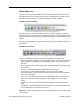


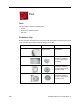

Table Of Contents
- PowerBook G4 (12-inch)
- Take Apart
- General Information
- Battery
- Feet
- Memory Door and Memory Card
- AirPort Extreme Card
- Keyboard
- Top Case
- Reed Switch Board and Cable: PowerBook G4 (12-inch)
- Hall Effect Sensor Board and Cable: PowerBook G4 (12-inch DVI)
- Hard Drive
- Modem
- DC-to-DC Board
- Heatsink and Fan Assembly: PowerBook G4 (12-inch)
- Heatsink: PowerBook G4 (12-inch DVI)
- Inner Frame: PowerBook G4 (12-inch)
- Inner Frame: PowerBook G4 (12-inch DVI)
- RJ11 Modem Board and Cable: PowerBook G4 (12-inch)
- RJ11 Modem Board and Cable: PowerBook G4 (12-inch DVI)
- Fan: PowerBook G4 (12-inch DVI)
- Sleep Light
- Logic Board
- DC-In Board
- Optical Drive
- How to Remove a Stuck Disc from the Slot-Load Drive
- Bluetooth
- Subwoofer
- Display Module
- Bottom Case
- Display Housing
- LCD Panel
- Inverter Board (and Antenna Cable Assembly)
- Hinges with Bezel Brace
- Display Bezel
- Troubleshooting
- Views
8 -
PowerBook G4 (12-inch) Take Apart
Feet
Procedure
Warning:
The glue used in this procedure can bond instantly to skin. Do not touch the
glue. In the event of contact, review the safety instructions at the end of this document. For
additional information, refer to the glue manufacturer:
Elmer's Products, Inc.
Columbus, OH. 43215-3799
www.krazyglue.com
1. Place the computer upside down on a clean, lint-free cloth or other nonabrasive
surface.
2. Select a foot from the kit that matches the plug on the bottom case. (Refer to the
images shown in the table.) Do not use a foot that does not match.
3. Make sure the plug area on the bottom case is clean. If any portion of the soft rubber
foot remains, remove it so that only the hard plastic plug is visible (as shown below).
Battery Plug Case Plug
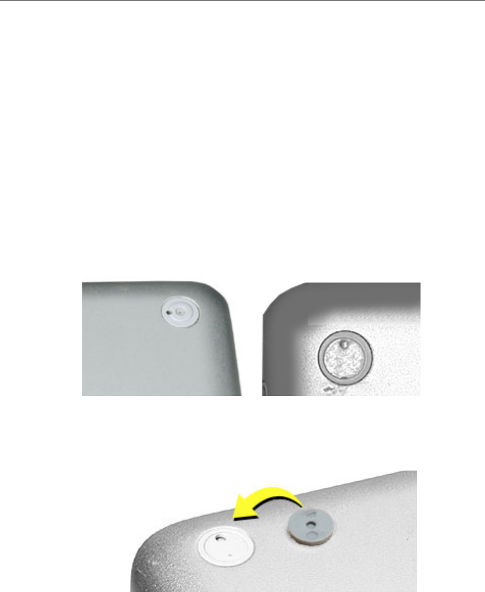
Important:
Notice the inner ring of the plug. When positioning the foot, make sure
the textured plane of the rubber foot fits into the compatible ring in the plug. This
ensures a balanced and level fitting.