
User Guide
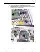
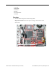
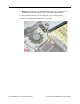

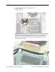

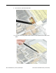

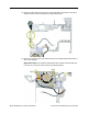
Table Of Contents
- PowerBook G4 (12-inch)
- Take Apart
- General Information
- Battery
- Feet
- Memory Door and Memory Card
- AirPort Extreme Card
- Keyboard
- Top Case
- Reed Switch Board and Cable: PowerBook G4 (12-inch)
- Hall Effect Sensor Board and Cable: PowerBook G4 (12-inch DVI)
- Hard Drive
- Modem
- DC-to-DC Board
- Heatsink and Fan Assembly: PowerBook G4 (12-inch)
- Heatsink: PowerBook G4 (12-inch DVI)
- Inner Frame: PowerBook G4 (12-inch)
- Inner Frame: PowerBook G4 (12-inch DVI)
- RJ11 Modem Board and Cable: PowerBook G4 (12-inch)
- RJ11 Modem Board and Cable: PowerBook G4 (12-inch DVI)
- Fan: PowerBook G4 (12-inch DVI)
- Sleep Light
- Logic Board
- DC-In Board
- Optical Drive
- How to Remove a Stuck Disc from the Slot-Load Drive
- Bluetooth
- Subwoofer
- Display Module
- Bottom Case
- Display Housing
- LCD Panel
- Inverter Board (and Antenna Cable Assembly)
- Hinges with Bezel Brace
- Display Bezel
- Troubleshooting
- Views

74 - PowerBook G4 (12-inch) Take Apart
Inner Frame: PowerBook G4 (12-inch DVI)
6. Near the fan, disconnect the two connectors shown
• four-pin connector
• two-pin connector
Replacement Warning: When reassembling the computer, notice the two black
insulated cables that run along the bottom of the fan. To avoid damaging the
cables, make sure that the thinner twisted cable is routed on top of the
thicker fan cable and that both cables are routed between the fan and the
modem standoff, as shown.