Service Source PowerBook G4 (15-inch 1.67/1.5GHz) 31 January 2005 © 2005 Apple Computer, Inc. All rights reserved.
Service Source Take Apart PowerBook G4 (15-inch 1.67/1.5GHz) © 2005 Apple Computer, Inc. All rights reserved.
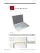
General Information Overview Identify the PowerBook G4 (15-inch 1.67/1.5GHz) by noting there is no AirPort Extreme card door in the battery well, as with previous 15-inch aluminum alloy body PowerBooks. General Information PowerBook G4 (15-inch 1.67/1.
Main feature differences from previous models: • Built-in AirPort Extreme • Illuminated keyboard on all models • Built-in fiber optic backlit keyboard—the fiber-optic mat has been replaced with a light panel integrated into the keyboard assembly • Trackpad and keyboard connect through USB, not directly to the power management system—impacts troubleshooting and resetting the power management unit (PMU) • 1.67GHz (and 1.5GHz) logic boards • 128MB VRAM w/ dual link DVI option on 1.
Important Memory Note Memory from the previous 15-inch (Titanium-series) PowerBooks is not compatible with this computer. Memory from the PowerBook G4 (15-inch FW800) and PowerBook G4 (1.5/1.33GHz) is compatible (not all memory compatible with the PowerBook G4 (1.5/1.33GHz) will be compatible with the PowerBook G4 (15-inch FW800)).
Tools The following tools are recommended for the take apart procedures. • ESD wrist strap and mat • Soft cloth • #0 Phillips screwdriver (magnetized) • #1 Phillips screwdriver (magnetized) • 4 mm socket wrench • 5 mm socket wrench • 1.
Serial Number Location The serial number is located in the battery bay. General Information PowerBook G4 (15-inch 1.67/1.
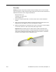
Foot Tools This procedure requires the following tools: • Foot kit • Tweezers or needlenose pliers • Soft cloth Preliminary Step Before you begin, check the foot location that needs replacement and verify that the case plug is attached. Also verify that the case plug, and the case foot in the kit, match the pictures below. Plug Area on Bottom Case Matching Foot Action Missing case plug Not available for replacement Replace the bottom case, or send to Apple Repair Center.
Procedure Warning: The glue used in this procedure can bond instantly to skin. Do not touch the glue. In the event of contact, review the safety instructions at the end of this document. For additional information, refer to the glue manufacturer: Elmer's Products, Inc. Columbus, OH. 43215-3799 www.krazyglue.com 1. Place the computer upside down on a clean, lint-free cloth or other nonabrasive surface. 2. Select a foot from the kit.
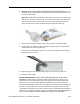
4. Warning: GLUE IS AN EYE AND SKIN IRRITANT. BONDS SKIN INSTANTLY. Do not touch the glue at any time. Before opening the glue, review the safety instructions at the end of this document. Important: The glue tube included in the kit is sealed until first use. Do not break the seal until you are ready to use the glue. To break the seal, hold the tube upright and away from you. Place the hollow nozzle cap on the tube and tighten it all the way down.
Battery Tools This procedure requires the following tools: • Soft cloth • Coin Part Location Preliminary Steps Warning: Always shut down the computer before opening it to avoid damaging its internal components or causing injury. After you shut down the computer, the internal components can be very hot. Let the computer cool down before continuing. Battery PowerBook G4 (15-inch 1.67/1.
Procedure Warning: If the computer has been recently operating, allow it to cool down before performing this procedure. 1. Shut down the computer. 2. Disconnect the power cord and any other cables connected to the computer. 3. Place the computer face down on a soft cloth. 4. Insert a coin in the battery lock slot and turn it one quarter turn clockwise. The battery should raise up slightly. Lift the battery out of the battery bay. 10 - PowerBook G4 (15-inch 1.67/1.
Memory Door and Memory Cards Tools This procedure requires the following tools: • Soft cloth • #0 Phillips screwdriver Part Location Preliminary Steps Before you begin, remove the battery. Memory Door and Memory Cards PowerBook G4 (15-inch 1.67/1.
Procedure Warning: If the computer has been recently operating, allow it to cool down before performing this procedure. 1. Place the computer face down on a soft cloth. 2. Remove the four screws from the memory door then remove the door. 922-6091 3.4 mm Note: If only one memory card is installed, the factory installs it in the bottom memory slot. Note: Memory must be removed from the top slot before removing from the bottom slot. 12 - PowerBook G4 (15-inch 1.67/1.
3. To remove memory cards, carefully spread the two locking tabs for the slot (top or bottom) away from the card on both sides and allow the card to pop up slightly. 4. Pull the card straight back and out of the memory slot. Memory Door and Memory Cards PowerBook G4 (15-inch 1.67/1.
Replacement Procedure Notes: • The top and bottom memory cards are inserted at different angles. • If installing two cards, install into the bottom slot first. • Align the notch in the memory card with the tooth in the slot before inserting. 1. To install a memory card into the bottom slot, insert the card at a low angle behind the locking tabs of the top slot. 14 - PowerBook G4 (15-inch 1.67/1.
2. Slide the card forward to the lower slot. Firmly push the card straight into the slot until it is fully and securely seated along its length. Note: If the back of the card drops down before it is fully seated, raise it up enough to push it fully into the slot. 3. Carefully spread the two locking tabs for the bottom slot away from the card on both sides while pushing the card straight down until the tabs click onto both sides of the card, locking it into place.
4. If installing a memory card in the top slot, follow the same procedures as the bottom slot except insert the card at a 30-degree angle, above the locking tabs. 5. Push the card in until it is firmly seated. 6. As with the bottom slot, spread the locking tabs for the top slot while pushing the card straight down until it locks into place. 16 - PowerBook G4 (15-inch 1.67/1.
7. Cards should be flat and secure on both sides. 8. Install the memory door. 9. Replace the battery. 10. Use Apple System Profiler to verify that the memory is recognized. (Choose the menu bar Apple logo () > About This Mac, click More Info..., select the System Profile tab, open the Memory Overview.) Memory Door and Memory Cards PowerBook G4 (15-inch 1.67/1.
Top Case Tools This procedure requires the following tools: • #0 Phillips screwdriver (magnetized) • 1.5 mm Hex key (or Torx T6) • Black stick (or other nonconductive nylon or plastic flat-blade tool) • Soft cloth • Multi-compartment screw tray Part Location 18 - PowerBook G4 (15-inch 1.67/1.
Preliminary Steps Before you begin, remove the following: • Battery • Memory door Procedure Note: This procedure removes the top case and keyboard assembly. The keyboard is removable only after removing the top case. 1. Place the computer face down on a soft cloth. 2. Remove the two screws inside the battery bay. 3. Remove the two screws from the memory bay. 4. Remove the four screws along the back edge. 922-6095 16.4 mm 922-6719 12.6 mm 922-6091 3.4 mm Top Case PowerBook G4 (15-inch 1.67/1.
5. With the display open, rest the computer on one side. Remove the three screws. 922-6091 3.4 mm 6. Turn over the computer and remove the three screws on the other side. 922-6091 3.4 mm 20 - PowerBook G4 (15-inch 1.67/1.
7. Open the computer slightly and rest it with the back facing up. Remove the two top screws along the back. Note: Do not remove the bottom screws. 922-6100 5.3 mm 8. Lay the computer right side up and open the display slightly past 90-degrees. 9. Remove the two hex screws at the back corners of the top case (a Torx T6 can also be used). 922-6096 1.5 mm Hex 4.4 mm Top Case PowerBook G4 (15-inch 1.67/1.
10. Along the left side, near the back, insert a black stick into the space between the top and bottom case. Work the black stick forward with a twisting motion until the black stick can be inserted on the left side of the front. 22 - PowerBook G4 (15-inch 1.67/1.
11. Loosen the back right side, if needed. 12. Work the left side up until the four catches over the optical drive slot release along the right side, then lift the top case straight up, slightly, to release it completely, but do not remove. Top Case PowerBook G4 (15-inch 1.67/1.
13. Lift the front of the top case and pivot along the back edge to about 45-degrees, to expose the keyboard flex cable connected to the logic board. Important: Do not lift off the top case or strain the keyboard flex cable. 14. Remove any Kapton tape from the keyboard connector on the logic board, then use a black stick to disconnect the flex cable. Lift off the top case. Replacement Note: When reinstalling, reapply Kapton tape where it was removed. 24 - PowerBook G4 (15-inch 1.67/1.
Replacement Procedure Note: If replacing the top case, remove the keyboard and transfer to the replacement top case. 1. Visually check to verify that all cables are connected and routed correctly with nothing raised up or incorrectly over a component. 2. Check perimeter wiring, where shown, to verify that it will not be caught or pinched by the top case during replacement. 3. Verify that the LVDS cable is secure and lays flat. Top Case PowerBook G4 (15-inch 1.67/1.
4. On the top case, check cable connections and routing. 5. Check that the perimeter metal tabs are not bent. Note: The metal quickly fatigues and can break off easily. Be extremely careful to gently straighten tabs, if needed. 26 - PowerBook G4 (15-inch 1.67/1.
6. Connect the flex cable from the top case to the logic board. 7. Lift the top case slightly and rotate it down over the bottom case (verify that the cable is folding properly) and align the corners. 8. Start at the right corner and guide the top case onto the bottom case. Use a black stick to carefully pull or push tabs slightly, if needed. Important Notes: • Some side screws have a flexible screw boss.
10. Close the computer, flip it over, and install the four back screws. 11. Install the two screws in the memory bay. 12. Install the memory door and four screws. 13. Install the two screw in the battery bay. 922-6095 16.4 mm 922-6719 12.6 mm 922-6091 3.4 mm 14. Replace the battery. 15. Testing the computer should include powering on, checking the keyboard and trackpad function. Operate the computer in a darkened room to check for keyboard backlight function. 28 - PowerBook G4 (15-inch 1.67/1.
Keyboard Tools This procedure requires the following tools: • #0 Phillips screwdriver • Black stick (or other nonconductive nylon or plastic flat-blade tool) • Kapton tape Part Location Preliminary Steps Before you begin, remove the following: • Battery • Top case Keyboard PowerBook G4 (15-inch 1.67/1.
Procedure The keyboard for these computers has a different construction, and different removal and installation procedures than previous models. Important Notes: • The keyboards are not interchangeable with previous models. Verify that the correct replacement keyboard is ordered, and/or top case if replacing. • The keyboard comes as a multi-layered assembly, and all include backlighting. Do not disassemble the keyboard assembly. Dust, fingerprints, or misalignment, can cause improper function and damage. 1.
3. Very carefully lift the front of the two connectors to release the keyboard flex cables, as shown. Important: The connectors are delicate. If damaged, the top case must be replaced. Replacement Note: Verify that the cables are fully inserted and secured straight. 4. Note the position, then carefully peel off the insulator film covering the back of the keyboard well. Reserve the film and keep it clean for reinstallation. Note: The film may be a different color and design than shown here.
5. Use needlenose pliers to straighten the four bend-tabs located along the bottom edge, as shown. These tabs lock down and stiffen the top edge of the keyboard. Important: The bend-tabs are delicate. Bend them carefully to avoid damage. Avoid overbending. 6. Remove the ten keyboard screws. 922-6718 1.6 mm 32 - PowerBook G4 (15-inch 1.67/1.
7. Note the six insert-tabs along the middle edge, and two on each side. The following procedures release these tabs so that the keyboard can be removed. 8. To prevent the keyboard from falling out, support it with your hand, and raise the top case up vertically. Note: The keyboard does not have adhesive under it, as in previous models. Keyboard PowerBook G4 (15-inch 1.67/1.
9. If needed, push through one of the top center keyboard screw holes, with the point of a black stick, to bow out the keyboard slightly. Important: Ensure that the hole used is a screw hole, or damage to other sensitive components may result. A black stick is used to avoid damaging the screw boss threads—do not use a metal tool. 10. Important: During this procedure, do not allow the tabs or metal edge of the keyboard to scrape along the cosmetic surface of the top case, or damage can result.
11. Use your finger to hold the bowed out keyboard. Continue to bow it out only enough for the tabs on one side of the keyboard to release cleanly. Repeat for the other side. Important: Do not bow the keyboard too much, or it may become permanently bent. Keyboard PowerBook G4 (15-inch 1.67/1.
12. Lift the keyboard up to release the tabs along the bottom edge and carefully thread out the flex cables. 36 - PowerBook G4 (15-inch 1.67/1.
Replacement Procedure When replacing the keyboard, here are some key points to ensure: • Prevention of scratches to the cosmetics of the top case • All tabs are properly seated • Keyboard lays flat • Cables not caught • Bend-tabs are not damaged • Screw holes align • Cable connectors are not damaged and cables secure properly • Kapton tape is applied as before • Insulator film is correctly installed 1.
2. Guide the keyboard’s flex cables through the slot in the top case, as shown. Make sure that they do not catch or bend behind the keyboard. 3. Lower the keyboard and seat all six tabs along the bottom, so that the keyboard sits flat and straight. 38 - PowerBook G4 (15-inch 1.67/1.
Important: During the next steps, do not allow the tabs or metal edge of the keyboard to scrape along the cosmetic surface of the top case, or damage can result. 4. While ensuring that the keyboard bottom stays straight and secure, hold the top of the keyboard in the middle, then with your other hand, bow in one side of the keyboard to engage the two tabs at the top into the top case. Important: Do not bow the keyboard too much, or it may become permanently bent. Keyboard PowerBook G4 (15-inch 1.67/1.
5. Use the heel of your hand to hold in place the edge of the keyboard that was just inserted while holding the top of the keyboard with a finger on that hand, then use your other hand to help bow in the remaining side of the keyboard until it can be engaged. 40 - PowerBook G4 (15-inch 1.67/1.
6. While supporting the keyboard in the top case, verify that the keyboard lays flat and that all the tabs have seated properly. Note: The keyboard will not sit flat if any of the tabs have not seated properly. If the side tabs are not seating or are binding, check the bottom edge of the keyboard to verify that all the tabs are seated and the bottom of the keyboard is straight. 7. Verify that the bend-tabs are not caught. 8. Lay the top case flat, and upside down. 9.
12. Insert the flex cables into their connectors and secure. Install Kapton tape in the same location as it was removed. 13. Replace the insulator film in the same locations as they were removed. Ensure the holes in the film match up correctly with the screw bosses. Avoid wrinkles and bulges. If installing a replacement top case, use the new film if supplied.
Backup Battery Tools This procedure requires the following tools: • Black stick (or other nonconductive nylon or plastic flat-blade tool) Part Location Preliminary Steps Before you begin, remove the following: • Battery • Top case Backup Battery PowerBook G4 (15-inch 1.67/1.
Procedure 1. Use a black stick to release the adhesive holding the backup battery to the optical drive then disconnect the backup battery cable. Note: The backup battery is held down by double-backed tape adhesive on its cover. 44 - PowerBook G4 (15-inch 1.67/1.
Replacement Procedure 1. Connect the backup battery cable to the backup battery and to the logic board. 2. Remove any protective adhesive cover on the replacement backup battery. 3. Position the backup battery precisely to the dimensions shown below. Note: Measurements are from the edge of the optical drive and the optical drive bracket to the backup battery board and the battery (not the protective cover).
4. Press where shown to secure the backup battery to the optical drive. 5. Reassemble the computer. 6. Testing the computer should include plugging in the power adapter and letting the backup battery charge for half an hour. Then power on the computer and disconnect the power adapter, set the system clock, put the computer to sleep, remove the main battery for five seconds and reinstall. The date and time should not reset. Also, insert an optical disc to verify that the optical drive functions properly.
Optical Drive Tools This procedure requires the following tools: • #0 Phillips screwdriver (magnetized) • Thin double-back tape (if the backup battery will not re-stick securely) • Black stick (or other nonconductive nylon or plastic flat-blade tool) Part Location Preliminary Steps Before you begin, remove the following: • Battery • Top case • Backup battery Optical Drive PowerBook G4 (15-inch 1.67/1.
Procedure 1. Remove the three screws from the drive holder. 922-6097 6.4 mm 2. Lift out the bracket. Replacement Note: Verify that the EMI gasket is securely in place. 48 - PowerBook G4 (15-inch 1.67/1.
3. Use a black stick to carefully disconnect the optical drive flex cable connector. 4. Remove the screw, shown. 922-6090 3.2 mm 5. Lift up at the rear of the drive and remove. Warning: Hold the optical drive at its side edges. Do put pressure in the middle. Optical Drive PowerBook G4 (15-inch 1.67/1.
6. Transfer the flex cable, side brackets and screws to the replacement optical drive. 922-6488 2.15 mm 7. To install the replacement optical drive, insert the front of the drive and ensure that the holes in the front brackets fit over the pins on the internal frame, while lowering the back of the drive into place. 50 - PowerBook G4 (15-inch 1.67/1.
8. Verify that both sides of the drive are fully seated, and reinstall the screw. 9. Connect the optical drive flex cable connector to the logic board. 10. Reassemble the computer. 11. Testing the computer should include powering on, inserting an optical disc and ejecting it to make sure the drive is aligned with the opening and functioning properly. Test the backup battery by plugging in the power adapter and letting the backup battery charge for half an hour.
How to remove a stuck disc from an MKE optical drive Important: These procedures apply to MKE optical drives, only. 1. Remove the four identical screws that hold the top cover to the drive. 2. Slide the top cover approximately 2 mm toward the back of the drive. Lift up the top cover to remove it. 52 - PowerBook G4 (15-inch 1.67/1.
3. Check the placement of the disc. It is either clamped to the turntable at the center of the disc, or it is wedged under one or more posts at the outer edge of the disc. 4. Holding the edge of the disc, press on the center clamp or hold the posts steady as you remove the disc from the drive. Important: Do not touch any key components located near the disc. 5. Replace the top cover on the drive so that the small hooks on the top cover fit into the slots on the bottom cover.
Hard Drive Tools This procedure requires the following tools: • #0 Phillips screwdriver (magnetized) • Black stick (or other nonconductive nylon or plastic flat-blade tool) Part Location Preliminary Steps Before you begin, remove the following: • Battery • Top case 54 - PowerBook G4 (15-inch 1.67/1.
Procedure 1. Remove the three screws from the drive holder. 922-6097 6.4 mm 2. Lift out the bracket. Hard Drive PowerBook G4 (15-inch 1.67/1.
3. Use a black stick to carefully disconnect the hard drive flex cable connector. 4. Lift up on the right side of the hard drive to remove. 56 - PowerBook G4 (15-inch 1.67/1.
5. Transfer the shield, side screws, rubber shockpads and the flex cable to the replacement hard drive. 922-6083 5.8 mm 6. Install the replacement hard drive and reassemble the computer. 7. When installing the replacement drive... to avoid exposing the hard drive flex cable contacts, as shown here,... Hard Drive PowerBook G4 (15-inch 1.67/1.
use a black stick to guide the foam (covering the contacts) past the logic board, while... guiding the rubber shockpads securely into the holes in the hard drive holder. 58 - PowerBook G4 (15-inch 1.67/1.
8. Make sure all shockpads are seated correctly. 9. When replacing the hard drive/optical drive holder, make sure that the Mylar shield is not caught. 10. Testing the computer should include powering on, keyboard and trackpad function, verify that the hard drive is recognized, and that the speakers, and modem works. Hard Drive PowerBook G4 (15-inch 1.67/1.
Modem Important: • The new flex cable no longer routes under the optical drive, as in previous models. • The flex cable’s logic board end slides into a new connector which has a hinged locking bar that lifts from the back. • There are two insulator washers, one on each side of the modem, on the modem screw nearest the logic board.
Preliminary Steps Before you begin, remove the following: • Battery • Top case • Hard drive Procedure 1. Remove the two screws. 922-6090 3.2 mm Important: The screw nearest the logic board uses two insulator washers. One on the screw and one on the internal frame under the modem. Make sure that these insulators are in place before reinstalling the modem. Modem PowerBook G4 (15-inch 1.67/1.
2. Disconnect the flex cable, by carefully raising up the lock bar on the back of the connector. Slide out the flex cable. Important: The connector is delicate, use care. 3. Turn the modem over and disconnect the flex cable connected underneath, and the RJ-11 cable. 62 - PowerBook G4 (15-inch 1.67/1.
Replacement Procedure 1. Connect the RJ-11 cable to the modem. 2. Verify that the modem RJ-11 cable is routed as shown. 3. Press the flex connector and socket together with your fingers to secure. Important: After the modem has been laid flat, do not press down on the middle of the modem board, or damage to the board can result. 4. Reinstall the modem screws then reassemble the computer and test the modem. Check the battery latch to make sure nothing is interfering with its rotation.
Bluetooth Tools This procedure requires the following tools: • Black stick (or other nonconductive nylon or plastic flat-blade tool) Part Location Preliminary Steps Before you begin, remove the following: • Battery • Top case Notes: • Replacing the 4-pin Bluetooth cable requires removing the Sound/DC-in board. • Replacing the Bluetooth antenna requires replacing the diversity board, and/or display rear housing. 64 - PowerBook G4 (15-inch 1.67/1.
Procedure 1. Guide the Bluetooth 4-pin connector and antenna cables from under the bottom case hardware. 2. Lift up the Bluetooth board. 3. Disconnect the Bluetooth antenna cable. 4. Use a black stick to disconnect the 4-pin connector. Bluetooth PowerBook G4 (15-inch 1.67/1.
5. If replacing the Bluetooth cable, remove the Sound/DC-in board and disconnect the cable. Then guide the cable through the space at the PC card cage button guide to remove. 6. Install the replacement Bluetooth board. Note: Use Kapton tape if needed to secure the shield around the board. 66 - PowerBook G4 (15-inch 1.67/1.
7. Route cables under the case hardware in the channel as shown, and verify that the antenna cable is seated in the cable clips on the speaker assembly. Note: The Bluetooth antenna cable secures with the modem cable in the channels along the left speaker. When re-securing, insert the Bluetooth antenna wire into the channel first, then the modem wire. Important: Check that cables are not routed between screw bosses or over case edge hardware. 8. Reassemble and test the computer.
Left Blower Tools This procedure requires the following tools: • #0 Phillips screwdriver (magnetized) • Black stick (or other nonconductive nylon or plastic flat-blade tool) Part Location Preliminary Steps Before you begin, remove the following: • Battery • Top case Note: Replacing the right blower requires removing the logic board. 68 - PowerBook G4 (15-inch 1.67/1.
Procedure 1. Disconnect the cables shown below. 2. Remove four screws. 922-6093 4.5 mm Left Blower PowerBook G4 (15-inch 1.67/1.
3. Lift out the blower. 4. Install replacement blower. Reassemble and test computer. Replacement Note: Ensure that Kapton tape is installed over the fins of the blower. 70 - PowerBook G4 (15-inch 1.67/1.
Ambient Light Sensor Boards Tools This procedure requires the following tools: • #0 Phillips screwdriver • #1 Phillips screwdriver • Black stick (or other nonconductive nylon or plastic flat-blade tool) Part Location Preliminary Steps Before you begin, remove the following: • Battery • Top case Ambient Light Sensor Boards PowerBook G4 (15-inch 1.67/1.
Procedure 1. To remove the left ambient light sensor board, remove any Kapton tape, then remove the two screws, and disconnect the connector from the logic board. Replacement Note: Reinstall any Kapton tape in the same place as it was removed. 922-6090 3.2 mm 72 - PowerBook G4 (15-inch 1.67/1.
2. To remove the right ambient light sensor, remove the two screws, then... 922-6475 9.5 mm 922-6090 3.2 mm lift up on the board to disconnect it from the logic board (its connector is on the bottom of the board). Ambient Light Sensor Boards PowerBook G4 (15-inch 1.67/1.
Note: The assembly consists of two pieces: the sensor board and a lens cover. Replacement Note: Assemble the replacement sensor board and lens cover before installation. 3. Press, where shown here, to secure the right ambient light sensor board connector to the logic board. 4. Reassemble and test the computer. 74 - PowerBook G4 (15-inch 1.67/1.
PC Card Cage Tools This procedure requires the following tools: • #0 Phillips screwdriver (magnetized) • 4 mm socket wrench • Black stick (or other nonconductive nylon or plastic flat-blade tool) Part Location Preliminary Steps Before you begin, remove the following: • Battery • Top case • Left ambient light sensor board PC Card Cage PowerBook G4 (15-inch 1.67/1.
Procedure During this procedure, the PC card cage is finessed out from under the left speaker. 1. Remove the screw and nut from the left speaker. 922-5840 4 mm 922-6090 3.2 mm 2. Use a black stick to disconnect the flex cable connector at the Sound/DC-In board. 3. Lift the RJ-11 modem cable and the Bluetooth antenna cable out of the two channels along the left speaker assembly. 76 - PowerBook G4 (15-inch 1.67/1.
4. Push the cables past the end of the speaker assembly. 5. Lift the back of the speaker assembly off the nut screw, and then pull the front end up and back, pivoting on the wires. 6. Disconnect the AirPort Extreme flex cable connector, then push it back out of the way. PC Card Cage PowerBook G4 (15-inch 1.67/1.
7. Disconnect the PC card cage flex connector, and remove the four screws. 922-6093 4.5 mm 922-6470 6.6 mm 8. Turn the computer counterclockwise to see the PC card cage eject button mechanism, located under the speaker. Notice the button pin captured in a hole in the mechanism. 78 - PowerBook G4 (15-inch 1.67/1.
9. Press the PC card cage eject button to extend it from the computer. 10. Warning: Use care when manipulating the PC card cage. The cage hardware is delicate. Using force, or pressing or lifting anywhere other than where shown, can break apart components on the cage. While holding the PC card cage eject button with one hand, use a black stick to lift up on the PC card cage slightly, where shown. Carefully lift the button mechanism off the pin of the button. Remove the button and reserve for replacement.
12. Before reassembly, verify the holes in the Sound/DC-in board, are aligned with the screw bosses under them on the bottom case so that the PC card cage screws will install. 13. Install the replacement PC card cage and eject button. Replacement Note: Ensure that the pin on the PC card cage eject button is secured by the hole in the cage mechanism. 14. Lightly install all four screws before tightening (note: longer screws go in the back by the flex cable), then tighten in the following order.
15. Reassemble the computer. Replacement Notes: • Verify that the Bluetooth antenna cable is inserted first into the two channels on the speaker, then the modem cable. • Also, verify that the modem and Bluetooth antenna cables are routed behind, and are not caught or causing pressure on the connectors. PC Card Cage PowerBook G4 (15-inch 1.67/1.
• Verify that cables are secured, with Kapton tape, into the recess off the edge of the blower cover, shown highlighted here, and do not ride over the blower cover. 16. Testing the computer should include inserting a PC card to check that it can be locked in and that the eject button works smoothly. Check that both speakers work, and that the trackpad and keyboard function properly. Check that the modem and Bluetooth operate. Operate the computer in a darkened room to check for keyboard backlight function.
AirPort Extreme Card & Flex Cable Tools This procedure requires the following tools: • #0 Phillips screwdriver (magnetized) • Black stick (or other nonconductive nylon or plastic flat-blade tool) Part Location Preliminary Steps Before you begin, remove the following: • Battery • Top case • PC card cage AirPort Extreme Card & Flex Cable PowerBook G4 (15-inch 1.67/1.
Procedure 1. Remove the two screws. 922-6472 4.5 mm 2. Slide out the AirPort Extreme card and flex cable assembly slightly, and peel up the Kapton tape to free the antenna cable from the card. 84 - PowerBook G4 (15-inch 1.67/1.
3. Firmly pull the antenna cable connector straight back from the card to disconnect it. 4. Firmly pull the flex cable straight back from the AirPort Extreme card to disconnect it. Replacement Note: Install the replacement card with the AirPort Extreme name up, and re-secure the antenna along the indent in the side, with Kapton tape. AirPort Extreme Card & Flex Cable PowerBook G4 (15-inch 1.67/1.
5. Reassemble the computer. 6. Testing the computer should include using Apple System Profiler to check that the AirPort Extreme card is recognized, test that the AirPort Extreme card is working, insert a PC card to check that it can be locked in and that the eject button works smoothly. Check that both speakers work, and that the trackpad and keyboard function properly. Check that the modem and Bluetooth operate. Operate the computer in a darkened room to check for keyboard backlight function.
Display Panel Assembly Note: On this model, the Display Panel Assembly is not available as a stand alone part.
Procedure 1. Remove the two screws along the back, closest to the bottom of the computer. 922-6100 5.3 mm 2. Open the computer display. 3. Lift the Bluetooth board up and disconnect the antenna cable. Replacement Note: The Bluetooth antenna cable secures with the modem cable in the channels along the left speaker. When re-securing, insert the Bluetooth antenna wire into the channel first, then the modem wire. 4. Disconnect the inverter cable. 88 - PowerBook G4 (15-inch 1.67/1.
5. On the right side of the computer, disconnect the LVDS cable. 6. Move the display to a 90-degree angle and remove the four screws. Important: Support the display from falling over before removing the last screw. 922-6471 10.25 mm 922-6098 13 mm Display Panel Assembly PowerBook G4 (15-inch 1.67/1.
7. Lift the display straight up and off of the computer without catching wires. 8. Install the replacement display panel assembly. Replacement Note: Make sure to capture the grounding loop with the back screw. 90 - PowerBook G4 (15-inch 1.67/1.
9. Replacement Note: Verify that the right clutch EMI gasket is securely in place. 10. Reassemble and test the computer. 11. Testing the computer should include testing that the display panel functions properly. Use Apple System Profiler to check that the AirPort Extreme card is recognized, test that the AirPort Extreme card is working, insert a PC card to check that it can be locked in and that the eject button works smoothly.
Logic Board Tools This procedure requires the following tools: • #1 Phillips screwdriver (magnetized) • EMI Gasket Kit (076-1164) • Black stick (or other nonconductive nylon or plastic flat-blade tool) • Alcohol pads If not ordering a replacement logic board, order: • Thermal Pads & Grease Kit (076-1165) If ordering a replacement heatsink, order: • Thermal Grease (922-6495) Note: Use a tray with divided compartments to organize the screws you remove. Part Location 92 - PowerBook G4 (15-inch 1.67/1.
Preliminary Steps Before you begin, run the computer until warm (if possible) to help soften the thermal material on the logic board, then shut it down and remove the following: • Battery • Top case • Right ambient light sensor board and lens cover Note: It may be helpful to remove the optical drive and hard drive to reduce the number of cables to control when replacing the logic board, if desired. Procedure 1. Disconnect the fourteen cables shown. Logic Board PowerBook G4 (15-inch 1.67/1.
2. Remove the two screws holding the right speaker and move the speaker and its wires down and away from the logic board. 922-6474 5.5 mm 3. Remove the eight remaining logic board screws, shown. 922-6473 6.9 mm 922-6472 4.5 mm 94 - PowerBook G4 (15-inch 1.67/1.
Warning: Do NOT allow the logic board to flex. Flexing the board can break solder joints to components. Give special attention at the narrow neck of the blower cutout. 4. Lift the left side slightly and remove the two connectors. Note: The thermal material should easily release. If not, apply slow constant pressure until it releases, avoid over flexing. Logic Board PowerBook G4 (15-inch 1.67/1.
Important: When removing the logic board, verify that the thin aluminum washer, attached over the screw notch, shown below, has not fallen off into the computer. Note: There may be another similar washer attached to a standoff on the heatsink, just below the board at this location. This is ok. Replacement Note: When handling the replacement logic board, verify that this washer is installed where shown below, and take care not to touch or bend it.
5. Carefully lift the left side of the board and pivot along the ports side. Support the board along its sides as it lifts to avoid flexing. Warning: Again, do not allow the board to flex, and give special attention at the narrow neck of the blower cutout. Important: Be careful not to touch or lose the thin metal washer stuck to the board, shown. Transfer the washer to the replacement board, if not present. 6. Carefully pull the port end of the board out of the port openings.
Warning: To avoid flexing the logic board, hold the board vertically along the wide sides. Do not hold the board by the ends or by the narrow neck at the blower cutout, or horizontally, as the board’s weight can cause excessive flex. Avoid touching the thin metal washer, shown, to prevent damage or dislodging. 98 - PowerBook G4 (15-inch 1.67/1.
Replacement Procedure 1. Verify that two rubber blocks and thin metal washer are installed on the replacement logic board. If not, transfer them from the replaced board. 2. Install the EMI gaskets that came with the replacement logic board, where shown below. (If not included, order the EMI gasket kit) Logic Board PowerBook G4 (15-inch 1.67/1.
The following procedures show how to replace the thermal materials: Warning: Whenever the logic board is separated from the heatsink, the thermal material must be replaced. Failure to do so can cause the computer to overheat and be damaged. Important: When removing thermal material: • Use a black stick to remove as much as possible • Use an alcohol pad to remove any remaining material on the mating surface.
4. Remove and replace the light colored thermal pad, shown below. Center the new pad over the raised mating surface and press it lightly into place, avoiding air pockets. Remove any protective coverings, if present. 5. Remove the thermal grease on the heatsink at the graphics chip location. Logic Board PowerBook G4 (15-inch 1.67/1.
6. Notes: • G751 thermal grease (922-6495) is used on the heatsink at the graphic chip location. • One syringe of thermal grease (922-6495) contains 0.5 cubic centimeter (cc) and is graduated in ml/cc. A milliliter (ml) equals a cubic centimeter (cc). Apply 0.6 cc of thermal grease in an “X” pattern from corner to corner of the mating surface, and then cross the center of the “X” with one line of grease the width of the center raised surface, as shown right and below. 102 - PowerBook G4 (15-inch 1.67/1.
7. If the logic board was removed to facilitate another procedure and will be reinstalled, with the same removal methods as above, remove all thermal material from the: • CPU chip • Graphics chip Important: Use extreme care not to damage the chip or logic board components. Logic Board PowerBook G4 (15-inch 1.67/1.
8. When replacing the logic board, guide the port side into the port openings on the bottom case. Connect the two connectors that go under the logic board on the left side of the board. Note: Use care not to catch cables under the board as it is lowered into place. 9. Attach the screws in the order shown. 922-6473 #1-3 6.9 mm 922-6472 #4-8 4.5 mm 10. Reassemble and test all ports, components and functions of the computer.
Right Blower Tools This procedure requires the following tools: • #1 Phillips screwdriver (magnetized) • Black stick (or other nonconductive nylon or plastic flat-blade tool) Part Location Preliminary Steps Before you begin, remove the following: • Battery • Top case • Logic board Right Blower PowerBook G4 (15-inch 1.67/1.
Procedure 1. Remove the three screws, then lift off the blower. 922-6093 4.5 mm 2. Install the replacement right blower. 3. Verify that Kapton tape covers the fins on the blower (left blower shown). 4. Reassemble the computer and test all ports, components and functions. 106 - PowerBook G4 (15-inch 1.67/1.
Right USB Board Tools This procedure requires the following tools: • #1 Phillips screwdriver (magnetized) • Black stick (or other nonconductive nylon or plastic flat-blade tool) Part Location Preliminary Steps Before you begin, remove the following: • Battery • Top case • Optical drive • Logic board Right USB Board PowerBook G4 (15-inch 1.67/1.
Procedure 1. Disconnect the flex cable. 2. Remove the two screws and guide the board out. 922-6472 4.5 mm 3. Transfer the EMI gasket to the replacement board if needed, or install a new gasket, as shown. 4. Install the replacement board and reassemble the computer. 5. Test all ports, components and functions of the computer. 108 - PowerBook G4 (15-inch 1.67/1.
Speakers Tools This procedure requires the following tools: • #0 Phillips screwdriver (magnetized) • #1 Phillips screwdriver (magnetized) • 4 mm socket wrench, or needlenose pliers • Black stick (or other nonconductive nylon or plastic flat-blade tool) Part Location Preliminary Steps Before you begin, remove the following: • Battery • Logic board • Left ambient light sensor board Speakers PowerBook G4 (15-inch 1.67/1.
Procedure Note: Lift up any Kapton tape as necessary and reserve for replacement. 1. Carefully lift wires out of routing channels on the left speaker. 2. Disconnect the speaker cable from the DC-In/Sound board. 110 - PowerBook G4 (15-inch 1.67/1.
3. Remove the screw and nut, shown here, then carefully lift out the speaker assembly. 922-5840 4 mm 922-6090 3.2 mm Replacement Note: Needlenose pliers may be helpful when reinstalling the nut. 4. Install the replacement speakers, and reassemble the computer. 5. Testing the computer should include using the Sound system-preference pane to test the left and right speakers. Speakers PowerBook G4 (15-inch 1.67/1.
Heatsink and Blowers Assembly Tools This procedure requires the following tools: • Torx T8 screwdriver (magnetized) • #1 Phillips screwdriver (magnetized) • Thermal Grease (922-6495) • Thermal Pads & Grease Kit (076-1165), if not replacing the heatsink • Alcohol pads Part Location Preliminary Steps Before you begin, remove the following: • Battery • Display panel assembly • Logic board 112 - PowerBook G4 (15-inch 1.67/1.
Procedure Note: The heatsink and blowers are one assembly part. 1. Remove the screws and lift out the heatsink and blower assembly. 922-6475 9.5 mm 922-6474 5.5 mm 922-6472 4.5 mm Important: Do not attempt to transfer blowers from one heatsink to another. This can create acoustic and heat issues. 2. If the heatsink was removed to facilitate another procedure and will be reinstalled, follow the procedures in the Logic Board chapter about replacement of thermal pads. 3.
4. Verify that Kapton tape covers the fins behind each blower, on the top and bottom. 114 - PowerBook G4 (15-inch 1.67/1.
5. To install the replacement heatsink, install the screws in the order shown. 922-6475 #7 9.5 mm 922-6474 #2, 6 5.5 mm 922-6472 4.5 mm 6. Reassemble and test all ports, components and functions of the computer. Heatsink and Blowers Assembly PowerBook G4 (15-inch 1.67/1.
Sound/DC-In Board Tools This procedure requires the following tools: • Torx T8 screwdriver (magnetized) • 5 mm socket wrench • Black stick (or other nonconductive nylon or plastic flat-blade tool) Part Location Preliminary Steps Before you begin, remove the following: • Battery • Top case • PC card cage • AirPort Extreme card • Display panel assembly • Speakers • Heatsink Note: Replacing the RJ-11 port and cable requires removing the hard drive. 116 - PowerBook G4 (15-inch 1.67/1.
Procedure 1. Remove the screws. 922-6098 13 mm 14.2 mm 2. Disconnect the power and flex cables. Sound/DC-In Board PowerBook G4 (15-inch 1.67/1.
3. Guide out the sound/DC-in board. Replacement Note: Install the “TO MLB” side of the flex cable to the logic board. 118 - PowerBook G4 (15-inch 1.67/1.
4. Turn the board over and disconnect the Bluetooth cable. 5. Remove the RJ-11 port, with attached cable, to transfer to the replacement board. The RJ-11 port slides off the sound/DC-in board but may be very tight. It may be helpful to pull on the port, or push it with the flat blade of a black stick, until it begins to move, then use a black stick to create leverage behind the port. Sound/DC-In Board PowerBook G4 (15-inch 1.67/1.
Replacement Note: If the replacement sound/DC-in board has an RJ-11 port installed, remove it and install the existing RJ-11 port. The RJ-11 board must go above the standoff. 6. Important: Connect the Bluetooth cable connector to the replacement sound/DC-in board. 7. Install the replacement sound/DC-in board. Important: While tightening the screws, push the board toward the port holes in the bottom case to ensure the DC plug is fully seated into its port.
• Verify that the screw pass-through holes, at the Bluetooth connector end of the board, line up with the screw bosses below them so that the PC card cage screws can install properly. 8. Connect the speaker, power, and flex cables. 9. Reassemble and test the computer. 10. Testing should include using Bluetooth to connect to another computer. Check the function of the modem port, DC-in port and the left USB port. Sound/DC-In Board PowerBook G4 (15-inch 1.67/1.
Bottom Case Assembly Part Location Preliminary Steps Before you begin, remove the following: • Battery • Modem • AirPort Extreme card and flex cable • Speakers • Right USB board • DC-in board • Bluetooth board and cables 122 - PowerBook G4 (15-inch 1.67/1.
Procedure 1. Verify that the following items are on the replacement bottom case: • Metal EMI shields • Display latch assembly • Sleep LED and wire connector assembly • Battery latch assembly • AirPort card adhesive (remove any adhesive cover) Bottom Case Assembly PowerBook G4 (15-inch 1.67/1.
2. If not present on the replacement bottom case, transfer the battery connector and cable assembly by removing the two screws. 922-6092 3.5 mm 3. If not present on the replacement bottom case, transfer the left hard drive holder by removing the two screws. 922-6472 4.5 mm 124 - PowerBook G4 (15-inch 1.67/1.
4. Install the EMI gasket (from the EMI gasket kit) on the replacement bottom case, as shown below, or transfer. 5. Reassemble and test all ports, components and functions of the computer, including battery operation. Bottom Case Assembly PowerBook G4 (15-inch 1.67/1.
Display Rear Housing Tools This procedure requires the following tools: • Torx T6 screwdriver (magnetized) • Black stick (or other nonconductive nylon or plastic flat-blade tool) • Something to rest the housing against while disconnecting the antenna cables • Soft cloth to protect the display face Part Location Preliminary Steps Before you begin, remove the following: • Battery • Top case • AirPort Extreme card • Display panel assembly 126 - PowerBook G4 (15-inch 1.67/1.
Procedure 1. Remove the two screws at the bottom corners of the display bezel. 922-6487 6.1 mm 2. Holding the display assembly up on one side, carefully push with your thumbs on the edge bead to disengage the rear housing from three tabs on the side of the bezel. Note: You will not fully disengage the housing from the bezel at this point. Display Rear Housing PowerBook G4 (15-inch 1.67/1.
A black stick may also be helpful to disengage the housing from the tabs. 3. Repeat step 2 on the other side of the display. 4. Use a black stick to carefully work around the bottom corners (clutch side). Important: The grey trim bead is part of the rear housing. Make sure to work the black stick on the correct side of the bead. 5. With the housing loosened on both sides, slide a black stick between the seam of the clutch cover and the rear housing. Twist the black stick as you go to increase separation.
6. To help disengage the clips under the clutch cover, you may need to push down with your thumb over the clip location on the clutch cover, while slightly pulling the rear housing to disengage. 7. When the housing is loosened on sides and bottom, run a black stick along the gap at each bottom corner to slightly separate the rear housing from the display assembly. Warning: The rear housing is connected to the display assembly with two antenna cables.
8. Place the display with rear housing face down on a soft clean cloth. 9. Tilt up the rear housing and rest it against something to access the cables opposite the LVDS connector. Be careful not to strain the cables. Warning: Handle the display by the edges only. Avoid pressure on the back of the display (the white area of the LCD panel). 10.
11. Tilt up the antenna board and unwrap its plastic insulator. Replacement Note: Reuse the plastic insulator. If it is torn, use a single layer of Kapton tape to secure the insulator on the antenna board. 12. Disconnect both antenna cables by pulling the cable connectors straight up and off of the board. Replacement Note: The black antenna cable connects to Main1, and the grey antenna cable connects to Aux1. Make sure to reinstall the protective cover, and secure it with Kapton tape.
13. The rear display housing includes the housing, logo, attached spacers, and two antenna cables. Replacement Notes: • Make sure the antenna cables are routed correctly and connected to the diversity board before securing the replacement rear housing on the display assembly. • Before installing, make sure the housing is clean and there are no foreign particles on the inside of the housing, especially around the logo diffuser. 14. Reassemble and test the computer. 132 - PowerBook G4 (15-inch 1.67/1.
Display Hook Assembly Tools This procedure requires the following tools: • #0 Phillips screwdriver (magnetized) • Soft cloth to protect the display face Part Location Preliminary Steps Before you begin, remove the following: • Battery • Top case • AirPort Extreme card • Display panel assembly • Display rear housing Display Hook Assembly PowerBook G4 (15-inch 1.67/1.
Procedure Important: Handle the display assembly by the edges only. Avoid pressure on the back of the display (the white area of the LCD panel). At the top edge of the display assembly, remove the four screws that secure the display hook assembly to the display bezel. Important: The screws are quite delicate. To avoid stripping the screws, make sure that the screwdriver fits correctly and that steady pressure is applied when removing and reinstalling the screws. 1.
Inverter Board Tools This procedure requires the following tools: • Black stick (or other nonconductive nylon or plastic flat-blade tool) • Soft cloth to protect the display face Part Location Preliminary Steps Before you begin, remove the following: • Battery • Top case • AirPort Extreme card • Display panel assembly • Display rear housing Inverter Board PowerBook G4 (15-inch 1.67/1.
Procedure Important: Handle the display assembly by the edges only. Avoid pressure on the back of the display (the white area of the LCD panel). 1. With the display assembly face down on a soft cloth, peel up the tape from the left end of the inverter board, if present. Replacement Note: Some units may have a 180-degree bend of the cables under the tape. Be sure to reinstall the cables in the same orientation. 2. Lift the edge of the tape up to remove the wrapped inverter board.
3. Disconnect the cable at the right end of the board. 4. Tilt up the inverter board, and disconnect the cable at the left end of the board. Inverter Board PowerBook G4 (15-inch 1.67/1.
5. Remove the inverter board from the display assembly. Replacement Note: A replacement inverter board is wrapped in a mylar insulator. Do not unwrap the board. Handle the replacement board carefully during installation to avoid bending the board. 6. Reassemble and test the computer. 138 - PowerBook G4 (15-inch 1.67/1.
Clutch Cover and Diversity Board Tools This procedure requires the following tools: • #0 Phillips screwdriver (magnetized) • Black stick (or other nonconductive nylon or plastic flat-blade tool) • Soft cloth to protect the display face Part Location Preliminary Steps Before you begin, remove the following: • Battery • Top case • AirPort Extreme card • Display panel assembly • Display rear housing • Inverter board Clutch Cover and Diversity Board PowerBook G4 (15-inch 1.67/1.
Procedure Important: Handle the display assembly by the edges only. Avoid pressure on the back of the display (the white area of the LCD panel). 1. With the display face down on a soft clean cloth, remove the five screws that attach the clutch cover to the bezel. 2. Replacement Note: Make sure to secure the ground wire of the diversity board with the screw, as shown. 140 - PowerBook G4 (15-inch 1.67/1.
3. Place the display on its top edge so you can access the clutch cover. Replacement Note: Notice the orientation of the cables at the ends of the clutch cover. When replacing the clutch cover, make sure the cables are in the same orientation. Clutch Cover and Diversity Board PowerBook G4 (15-inch 1.67/1.
4. Starting at the diversity board end of the clutch cover, pinch and squeeze the clutch cover with one hand while you use the other hand to press the clutch cover end off of the display assembly. 5. Support the display as you remove the other end of the clutch cover. 142 - PowerBook G4 (15-inch 1.67/1.
6. Lift the diversity board with attached cables out of the clutch cover. Replacement Warning: The clutches on the display bezel are not self-aligning. Do not remove the bezel clutches or their screws (see Display Clutch chapter). Clutch Cover and Diversity Board PowerBook G4 (15-inch 1.67/1.
7. Replacement Note: When installing the clutch cover, make sure the screw holes align. 8. Reassemble and test the computer. 144 - PowerBook G4 (15-inch 1.67/1.
LVDS Cable Tools This procedure requires the following tools: • Soft cloth to protect the display face • Black stick (or other nonconductive nylon or plastic flat-blade tool) Part Location Preliminary Steps Before you begin, remove the following: • Battery • Top case • AirPort Extreme card • Display panel assembly • Display rear housing • Inverter board • Clutch cover and diversity board LVDS Cable PowerBook G4 (15-inch 1.67/1.
Procedure Warning: To avoid damage, pooling, or white spots, handle the display assembly by the edges only. Avoid pressure on the back (white area) of the panel. 1. With the display assembly face down on a soft cloth, peel up the tape from the LVDS connector, and disconnect the cable from the LCD panel. Important: When reconnecting the LVDS cable, make sure it is fully seated. Secure the cable with one layer of Kapton tape only on the metal of the connectors.
2. Peel up the metal tape securing the clutch end of the LVDS cable and reserve for reinstallation, or install new. 3. With the clutch cover removed, note the position of the LVDS cable on the clutch post. It is held in place with adhesive. Replacement Note: Be sure to position the replacement LVDS cable under the clutch post as shown. LVDS Cable PowerBook G4 (15-inch 1.67/1.
Replacement Note: Remove the protective strip covering the adhesive on the replacement LVDS cable before installing. 4. Remove the LVDS cable from the display assembly. 5. Reassemble and test the computer. 148 - PowerBook G4 (15-inch 1.67/1.
LCD Panel Tools This procedure requires the following tools: • #0 Phillips screwdriver (magnetized) • Black stick 922-5065 (or other nonconductive nylon or plastic flat-blade tool) • Isopropyl alcohol wipes (for removing adhesive residue) • Soft cloth to protect the display face • LCD Panel Spacer Kit 076-1069 (if not installed/included with replacement LCD panel) • Bezel Adhesive Strips 922-6733 (if not included with replacement LCD panel) Part Location LCD Panel PowerBook G4 (15-inch 1.67/1.
Preliminary Steps Before you begin, remove the following: • Battery • Top case • AirPort Extreme card • Display panel assembly • Display rear housing • Inverter board (must disconnect inverter cable to LCD) • Clutch cover and diversity board (optional) • LVDS cable (must disconnect from LCD panel) Procedure Warning: Handle the LCD panel by the edges only. To avoid damage, pooling, or white spots, do not press on the front or back of the LCD panel. 1. Position the display face down on a clean soft cloth. 2.
4. Hold the LCD and bezel together and turn it so the LCD faces up. 5. Carefully lift up on the top of the bezel to separate it slightly from the LCD. Warning: • Adhesive holds the bottom of the LCD and bezel together. Do not lift the bezel too far or damage to the LCD frame will result. • If too much pressure is applied to the bezel, it can be bent out of alignment. 6. Guide a black stick into the gap between the metal LCD frame and the bezel.
7. Lift the bezel off of the LCD panel. If installing a replacement LCD panel 1. Verify that three spacers are installed. If not, you need to install them—one along each side and one longer one along the top of the LCD panel. Important: • Do not install spacers if they are already installed on the LCD panel. • When installing spacers, be careful to align them properly with the screw holes. 152 - PowerBook G4 (15-inch 1.67/1.
Transfer or verify the sleep magnet installation 1. The round magnet on the back of the LCD panel triggers the computer’s sleep sensor. 2. If you are replacing the LCD panel, transfer the magnet to the new panel. Do not transfer the half-donut shaped holder, if present. If the holder came installed on the replacement panel, install the magnet in the center. 3. Important: Secure the magnet with a single piece of Kapton tape.
If reinstalling the bezel 1. Use Isopropyl alcohol wipes and a black stick to remove any residual adhesive along the lower inside edge of the bezel. Rub the wipes vigorously over the adhesive and scrape with the black stick. Verify that the adhesive is completely removed so that there are no clumps of adhesive remaining that will create an uneven surface. Warning: Sharp edges may be present. 2. Install the two replacement adhesive strips along the inside bottom edge.
Display Bezel Tools This procedure requires the following tool: • Torx T8 screwdriver (if transferring clutches to a replacement bezel) Part Location Preliminary Steps Before you begin, remove the following: • Battery • Top case • Display panel assembly • Display rear housing • Inverter board • Clutch cover and diversity board • LVDS cable • LCD panel Display Bezel PowerBook G4 (15-inch 1.67/1.
Procedure Important: Do not remove or loosen screws on the clutches. The clutches are not selfaligning and even a 0.3 mm shift will be noticeable. Important: If uneven pressure is applied to the bezel, it can be bent out of alignment. Avoid twisting the bezel. With all preliminary steps performed, the bezel is the remaining part. Replacement Procedure If installing a replacement bezel 1. Remove the clutch block and clutch assembly on the replacement bezel, if present.
Important: • If installing a replacement LCD panel, verify that three spacers are installed (see LCD Panel chapter). • Handle the LCD panel by the edges only. Avoid pressure on the back of the panel (the white area of the LCD panel). 2. Holding the sides of the LCD panel and the sides of the bezel, carefully align the LCD panel over the inner edges of the bezel. 3. Lower the LCD panel and press its outside edges and the bezel into place. 4. Reassemble and test the computer.
Display Clutch Tools This procedure requires the following tools: • #0 Phillips screwdriver (magnetized). • Torx T8 screwdriver (if transferring to a replacement bezel) Part Location Preliminary Steps Before you begin, remove the following: • Battery • Top case • Display panel assembly • Display rear housing • Inverter board • Clutch cover and diversity board 158 - PowerBook G4 (15-inch 1.67/1.
Procedure Important: Do not remove or loosen screws on the clutches, except in the manner described below. The clutches are not self-aligning and even a 0.3 mm shift will be noticeable. Important: If too much pressure is applied to the bezel, it can be bent out of alignment. Avoid flexing the bezel. If transferring clutches to a replacement bezel Important: Do not remove or loosen screws on the clutches. 1.
2. When installing the replacement clutch, be sure all openings align with the pins or holes on the shim and bezel. 3. Hold the clutch firmly against the bezel when installing the screws. 4. Reassemble and test the computer. 160 - PowerBook G4 (15-inch 1.67/1.
Service Source Troubleshooting PowerBook G4 (15-inch 1.67/1.5GHz) © 2005 Apple Computer, Inc. All rights reserved.
General Information Wire and Flex Cables With the very thin enclosure design and dispersed circuit board, a large number of flex cables are used in this computer. In addition, there are a variety of wire cable harnesses as well. Many of these cables carry multiple types of signals. Here is a list of the cables and the signals that run across them. If you notice a group of functions not working, it is likely that the cable is not properly inserted or the connector is damaged.
Cable or Flex Cable Name Signal(s) Running Through It Optical drive flex (to logic board) Optical data, power, and control signals PC Card cage flex (to logic board) PC card data and power Power Button cable Power-on signal RJ-11 cable (to modem) Analog phone signal Right USB flex Right USB signal and power Sleep LED cable (to logic board) Power to sleep LED Sound/DC-in board flex (to logic board) Bluetooth data Left USB connector Left ambient light sensor Digital audio in/out Sound/DC-in bo
Hardware Troubleshooting Tools and Tips Apple Hardware Test 2.5 (AHT) Notes: • Starting with Apple Hardware Test 2.5, the customer must first select a language. • Starting with the PowerBook G4 (17-inch), the Apple Hardware Test software will be incorporated into the Software Install and Restore DVD. There is no separate CD for this diagnostic. • Currently, the test image is now posted on Service Source online. • Apple Hardware Test 2.0.
Apple Service Diagnostic (ASD) MacTest Pro software does not work on this computer since the PowerBook G4 (15-inch FW 800) and forward are Mac OS X only systems. ASD is the replacement and can be downloaded from Knowledge Base article 112125: Service Diagnostics Matrix. Important: ASD is not backward compatible with PowerBook computers prior to the PowerBook G4 (1GHz/867MHz). Apple Service Diagnostic Main screen: Apple Service Diagnostic Select Tests tab: 4 - PowerBook G4 (15-inch 1.67/1.
Apple Service Diagnostic Hardware Info tab: Apple Service Diagnostic Test Log tab: General Information PowerBook G4 (15-inch 1.67/1.
Power Button pads on logic board With the top case removed, the power button is disconnected. Instead of having to reconnect the top case to turn on the system, there are two pads on the logic board that can be shorted across (with a tool like a flat blade screwdriver) to act as the power button. These pads are located near the edge of the logic board, just above center of the hard drive. It is marked POWER BUTTON. The pads are separated with a vertical white line.
PMU RESET pads on logic board In addition to the power button pads on the logic board, there are pads for PMU RESET, which work when their pads are shorted together (with a tool like a flat blade screwdriver). The pads are separated with a white horizontal line between the pads. The pads are located near the edge of the logic board, just above center of the hard drive.
Software Troubleshooting Tips and Tools Mac OS X only Starting with the PowerBook G4 (17-inch), the system will no longer boot into Mac OS 9. Mac OS 9 applications can still be used, but only in the Mac OS X classic mode. In locations such as the Startup Disk system preference pane, a Mac OS 9 folder will not show up as an option. Login window and account Mac OS X requires at least one user account to be established. This is the Administrator’s account.
To start up into Safe Mode (to Safe Boot), do this: 1. Be sure the computer is shut down. 2. Press the power button. 3. Immediately after you hear the startup tone, press and hold the Shift key. Note: The Shift key should be held as soon as possible after the startup tone but not before. 4. Release the Shift key when you see the screen the gray Apple and progress indicator (looks like a spinning gear). During the startup, you will see "Safe Boot" on the Mac OS X startup screen (shown below).
Hardware Symptom Charts How to Use the Symptom Charts The Symptom Charts included in this chapter will help you diagnose specific symptoms related to the product. The steps to solve a symptom are listed sequentially. You might not need to perform every step before the symptom is solved. Start with the first step, and then test for the symptom. If the symptom persists, replace any modules you removed, go to the next step, and test again. Continue down the list until the symptom is solved.
Power Adapter Note The system was designed to use the Apple 65-Watt Portable Power Adapter that came with your computer. The previous 45-Watt Apple power adapter for PowerBooks is plug compatible, but it may not provide sufficient power during some activities and power may be drawn temporarily from the battery. You can identify the Apple 65W Power Adapter by its markings (see photo).
Startup The computer will not power on (no blower movement, hard drive spin up and display is not lit) 1. Remove any connected peripherals and eject any PC card. 2. Check that the battery has enough charge to start the computer by pressing the button next to the LEDs on the battery. At least one LED must light solid (not flashing). 3. Connect a known-good Apple 65W Portable Power Adapter and power cord or plug to a known-good power outlet; make sure the DC plug is firmly inserted.
11. Reseat these flex cables: • Sound/DC-in flex cable • Hard drive flex cable (will boot to flashing folder) • Optical drive flex cable • PC card cage flex cable • Trackpad flex cable • Right USB flex cable • Modem flex cable If the computer starts up, inspect the flex cable connector and its connector on the logic board for damage and replace the damaged parts. 12. Remove AirPort Extreme Card. 13. Try known-good Sound/DC-in board. 14. Replace logic board.
Blue screen appears (a spinning disc cursor may also be visible), Prohibitory Sign appears, Restart dialog box appears (Mac OS X 10.2 kernel panic window), or Gray screen during startup Prohibitory Sign Kernel Panic dialog box 1. Make sure all external devices are disconnected and any PC card ejected. If kernel panic goes away, troubleshoot the external device by reconnecting each device until the panic occurs. 2.
Flashing question mark appears on the screen Note: This system will only boot the Mac OS X system that shipped with this computer or later. It does not support booting into Mac OS 9. 1. Start up from the software install and restore DVD that came with the computer (hold down the "C" key during restart). 2. When the Installer opens, from the Installer menu, select Open Disk Utility. 3. When the Disk Utility opens, on the left hand side, all disk and volumes are listed.
System shuts down intermittently Important: This issue can be a result of not using the 65W power adapter with the PowerBook G4 (15-inch FW 800) or later computers. Confirm with the customer which adapter they were using when having this problem. The adapter can be identified by 65W in the name and markings, and the metal securing-stud on the plug connector. 1. Disconnect all external peripherals and eject any PC card. 2. Make sure a known-good fully charged battery is fully inserted.
Application Quits, Kernel panic or other booting problems 1. If a specific application quits, replace the application. Verify the application is compatible with OS X. 2. Clear parameter RAM. Hold down Command-Option-P-R during startup until you hear a second startup chime. 3. Run Disk Utility from the Software Install and Restore DVD. 4. Perform a clean install of system software with the software install and restore disc that came with the computer.
Computer beeps twice at startup 1. Two beeps means that EDO memory is installed in the RAM expansion slot. The PowerBook does not accept EDO memory. 2. Replace RAM card(s) with known-good and compatible RAM and restart. • If symptom repeats, replace logic board. Computer beeps three times at startup 1. Three beeps means that no RAM banks passed memory testing. 2. If a RAM card is installed in the upper expansion slot (if not, skip to next step), remove it and restart.
AirPort Extreme Card AirPort Extreme Card not recognized 1. In Mac OS X, use Software Update in system preferences or see the Apple Software Updates web page to make sure the latest version of AirPort Extreme software is installed. 2. Restart the computer. 3. Open AirPort in system preferences and make sure AirPort is on and Base Station is selected. 4. Check the AirPort Extreme Card flex cable connection to the logic board. 5. Remove and reinstall the AirPort Extreme software. 6.
Battery Battery will not pop up 1. Flip over the unit and turn the battery latch clockwise. 2. If the battery does not pop up, use a small plastic flat-blade tool to pry up the battery around the battery latch. 3. Verify proper latch operation, by exercising the latch. If it does not move smoothly or evenly, replace the bottom case. 4.
Warning: Resetting the power manager will permanently remove a RAM disk, if present, and all of its contents. You will also need to reset the date and time (using the Date & Time system preference pane). 7. Make sure the Sound/DC-in cable is firmly connected. Look for damaged insulation or wires. 8. Replace Sound/DC-in power cable. 9. Replace Sound/DC-in board. 10. Replace logic board.
• The battery has a defect. – Symptoms include, but are not limited to, a relative new battery that will not charge at all, reports an “X” in the menu bar icon, status light on its case that will not go out. In the first two cases, the battery may need calibration—try this first.
Display Display latch not working Note: When the display is being closed, a latch hook in the top of the display housing should be magnetically pulled down through the slot in the top case and secured by the latch mechanism. When the latch button is pushed, the hook should release and retract into the display housing. 1. See the Latch Adjustment chapter in the Adjustments section of this service manual to verify the latch mechanism and latch hook operation and make adjustments, if necessary. 2.
5. If the number of subpixel anomalies is acceptable, explain to the customer that the pixel anomalies are within specifications, and no repair is necessary. Important: Do not release the specifications to customers. Instead, inform them that a certain number of subpixel anomalies are considered acceptable, and these factors apply to all manufacturers using LCD technology—not just Apple products.
Keyboard No response from any key on keyboard 1. Remove any connected peripherals and eject any PC card. 2. Attach an external USB keyboard, if it doesn’t work, go to step 6. 3. Turn off the computer. Check the keyboard flex cable connection to the trackpad, and the trackpad flex cable connection to the main logic board (especially check the connectors for damage). 4.
2. Check the keyboard backlight cable connection to the trackpad, if bad, replace the top case. 3. Replace the left and right ambient light sensors. 4. Replace logic board. Keyboard is partially illuminated. 1. Check the keyboard backlight cable connection to the trackpad assembly and the trackpad flex cable connection to the logic board. If the connections look good, replace the keyboard. 2. Replace keyboard. Microphone The microphone is not working 1.
Modem No modem dial tone 1. Check that the correct modem is selected in the Network Port Configuration section of the Network system preferences. 2. Verify known-good analog (not digital) telephone line. 3. Verify known-good RJ-11 telephone cable. 4. Verify RJ-11 cable is not plugged into Ethernet port (should not be physically possible with this PowerBook). 5. Inspect RJ-11 connector for pin damage. 6. Verify RJ-11 telephone cable is firmly installed in the modem port. 7.
Modem intermittently disconnects or low performance 1. Verify known-good RJ-11 telephone cable (for example, the retaining clip is not broken off) and it is firmly installed when used. If telephone cable is bad, replace it. 2. Ask if issue happens with only one particular phone line, but not another. The problem may be an issue with that particular phone line. Under bad line condition, try setting the modem script to start with a slower connect rate such as “Apple Internal 56K Modem (v.34).” 3.
Optical Drive The optical drive does not accept CD or DVD disc (mechanical failure) 1. Verify disc is not warped and is a 12 cm circular disc. 2. Check that a small disc is not stuck inside, or other foreign objects. Remove drive from system to extract disc. 3. Verify disc is pushed almost all the way into the slot. 4. Check the optical drive flex cable. 5. Replace optical drive. The optical drive does not eject CD or DVD disc 1.
Difficulty writing to optical media 1. Verify the correct type of disc is being used. 2. Try a different brand or speed of CD-R disc. Note: Some brands of 24x or 32x CD-R media may not work with the SuperDrive. Note: There are two factors in the ability for the optical drive to write to media. First, there are varying qualities of blank optical media. Some media are made to such low specifications that the ability for the drive to write to it is marginal.
PC Card PC Card will not insert into the PC Card slot 1. Make sure the PC Card eject button is in, before attempting to insert a PC Card, and there is no foreign object lodged in the card cage. 2. Make sure the PC Card is right side up (cards are keyed and cannot be inserted upside down). 3. Verify the PC Card is not warped or damaged in any way; if so replace the card. 4. Try a different PC Card. 5. Carefully raise the PC Card slot cover and check for a foreign object inside the slot. 6.
A USB device not recognized by computer Note: If you are trying to use a serial device with a USB/Serial adapter, check with the manufacturer of the adapter for compatibility. 1. Completely shut down, then press the power button to start the computer. 2. Verify current driver for the device is installed. 3. If a camera, turn on camera after initiating download with camera application. 4. Try the other USB port. 5. Try different USB device on same port. 6. Eliminate chain by plugging in only one peripheral.
Sound No sound heard and the Speakers section of the Sound system preference pane indicates that an external device is plugged in (to the headphone jack or USB ports) 1. If there is nothing plugged into the headphone jack or USB ports, under the Output tab of the Sound system preference pane should be set to the internal speakers. 2. If not, and if nothing is plugged in, try plugging in headphones or external speakers. Restart the computer. Remove the device. 3.
9. Check speaker cable. Verify left and right cable connections. 10. Check with headphones or external speaker, if audio is heard, replace speaker assembly. 11. Replace sound board flex cable. 12. Replace sound board. 13. Replace the logic board. Distorted sound from speakers 1. Verify sound is correct with external speakers/headphones. If sound is correct, check speaker wire and connections. 2. In Sound system preference pane, check balance. 3.
Trackpad The cursor does not move when you are using trackpad 1. Verify that no USB device is connected. 2. Boot from the Software Install and Restore DVD to verify that it is not a software problem. If the trackpad works, restore the system software. 3. Reset the power manager. See new procedures under the “Resetting the Power Manager Unit (PMU)” heading in the Hardware Troubleshooting Tools and Tips section. 4. Check trackpad flex cable connection to the logic board. 5. Replace top case. 6.
Video No display, or dim display, but computer appears to operate correctly 1. Remove any connected peripherals. 2. Make sure F1 key is not stuck down. 3. Press the F2 key (with the fn key pressed and not pressed) to increase the screen brightness settings. 4. Reboot the computer—hold down the Control and Command keys and press the Power button to restart the computer. Or, press and hold the Power button for 5 to 10 seconds to shut down the computer, then press the Power button to restart. 5.
No display, or dim display, but can display external video 1. Remove any connected peripherals. 2. Open Display system preference panel and check brightness. If works, replace keyboard. 3. Check connection of the inverter cable to the main logic board. 4. Check inverter cable connection to the inverter board and the inverter to the LCD cable connection. 5. Replace inverter board. 6. Replace the diversity board and cable assembly. 7. Replace display panel. 8. Replace logic board.
Misc. Symptoms The Date and Time settings reset all the time Note: Resetting the power manager or PRAM resets the date and time. 1. Do a backup battery test: • Set the date and time. • Perform a Shut Down from the Apple menu. • Remove the main battery and disconnect the power adapter for 10 minutes. • Connect the power adapter, insert the battery, and power on the computer. • If the date and time were lost the backup battery may be dead or discharged.
Service Source Views PowerBook G4 (15-inch 1.67/1.5GHz) © 2005 Apple Computer, Inc. All rights reserved.
PowerBook G4 (15-inch 1.67/1.
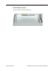
Display Rear Housing, with Logo and Diffuser 922-6018 PowerBook G4 (15-inch 1.67/1.
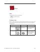
922-5840 922-6718 922-6488 922-6090 Hexnut 4 mm #0 Phillips 1.6 mm #0 Phillips 2.15 mm #0 Phillips 3.2 mm Speaker Keyboard Optical Drive Brackets AirPort Chamber ALS Boards Modem Optical Drive, Right Speaker (Left) Bezel to LCD 922-6091 922-6092 922-6096 922-6093 #0 Phillips 3.4 mm #0 Phillips 3.5 mm 1.5 mm Hex 4.4 mm #0 Phillips 4.