Service Source PowerBook G4 (17-inch Double-Layer SD) PowerBook G4 (17-inch 1.67GHz) PowerBook G4 (17-inch 1.5GHz) PowerBook G4 (17-inch 1.33GHz) 19 October 2005 © 2005 Apple Computer, Inc. All rights reserved.
Service Source Basics PowerBook G4 (17-inch Double-Layer SD) PowerBook G4 (17-inch 1.67GHz) PowerBook G4 (17-inch 1.5GHz) PowerBook G4 (17-inch 1.33GHz) © 2005 Apple Computer, Inc. All rights reserved.
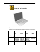
General Information Overview Some key features that distinguish these computers from the previous 17-inch PowerBook: PowerBook G4 (17-inch Double-Layer SD) PowerBook G4 (17-inch 1.67GHz) PowerBook G4 (17-inch 1.5GHz) PowerBook G4 (17-inch 1.33GHz) Microprocessor 1.67 GHz 1.67 GHz 1.5GHz 1.
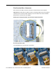
From the exterior, the PowerBook G4 (17-inch Double-Layer SD) physically is identical to its predecessor, the PowerBook G4 (17-inch 1.67GHz). The quickest ways to identify the PowerBook G4 (17-inch Double-Layer SD) computer: • If the system is bootable, power it on. After pressing the power button the sleep LED light comes on solid and stays on until video appears onscreen. • Also the "About this Mac." Under Memory, shows DDR2 memory.
Main feature differences from the previous models: • Higher resolution 17-inch display, 1680 x 1050, 116 dpi (previously 1440 x 900, 100 dpi) – Prism technology is used to increase the screen brightness from 150 nits to 220 nits • Support DDR2 memory up to 2GB • Double-Layer SuperDrive allows user to burn two layers through a single side of a double-layer burnable disk.
Flex cable compatibility Warning: The logic board will be damaged if the wrong sound board or modem flex cable is used. The sound cable marked PowerBook 17" 1.33GHz or greater can NOT be used on the PowerBook G4 (17-inch 1.67GHz) computer. Cables from the earlier PowerBook G4 (17-inch) system are also NOT compatible. The cables must be marked as indicated in the following chart: PBG4 17" Double-Layer SD PBG4 17" 1.67GHz PBG4 17" 1.5GHz PBG4 17" 1.33GHz N/A PBG4 17" 1.67GHz or greater PBG4 17" 1.
Tools The following tools are recommended for the take apart procedures. • ESD wrist strap and mat • Soft cloth • #0 Phillips screwdriver (magnetized) • #1 Phillips screwdriver (magnetized) • 4 mm socket wrench • Tweezers (or needlenose pliers) • Needlenose pliers • Torx T6 screwdriver • Torx T8 screwdriver • Black stick (nylon probe tool 922-5065) (or other nonconductive nylon or plastic flatblade tool) • Multi-compartment screw tray (such as a plastic ice cube tray) • Kapton® tape (922-1731 (0.
Zero Insertion Force Connectors Zero insertion force (ZIF) connectors are used in several locations in the computer. Important: The locking bar on the ZIF connector is extremely fragile and is not intended to separate from the connector. When releasing a bar, use extreme care and a restrained light pressure to move the bar only slightly. Warning: If a locking bar breaks, you will need to replace the board. To release the flex cable Use a flat-blade tool to move the bar on both sides.
To connect a flex cable Make sure the locking bar is released, then slide the end of the flex cable all the way into the connector. Hold the cable in place, then slide the locking bar into the connector on both sides to secure. Important: Verify that the cable is straight. Use either the alignment mark, if present, or the metal edge on the cable as a guide to ensure the cable is straight.
Service Source Take Apart PowerBook G4 (17-inch Double-Layer SD) PowerBook G4 (17-inch 1.67GHz) PowerBook G4 (17-inch 1.5GHz) PowerBook G4 (17-inch 1.33GHz) © 2005 Apple Computer, Inc. All rights reserved.
Feet Tools This procedure requires the following tools: • Foot kit • Tweezers or needlenose pliers • Soft cloth Preliminary Step Before you begin, check the bottom case of the computer and compare it with the images in this table. Make sure the foot you want to replace has an intact plug on the bottom case. Feet Plug Area on Bottom Case Matching Foot Action Missing plug Not available for replacement Replace the bottom case, or send the computer to the Apple Repair Center for repair.
Procedure Warning: The glue used in this procedure can bond instantly to skin. Do not touch the glue. In the event of contact, review the safety instructions at the end of this section. For additional information, refer to the glue manufacturer: Elmer's Products, Inc. Columbus, OH. 43215-3799 www.krazyglue.com 1. Place the computer upside down on a clean, lint-free cloth or other nonabrasive surface. 2. Make sure the plug area on the bottom case is clean.
3. Warning: GLUE IS AN EYE AND SKIN IRRITANT. BONDS SKIN INSTANTLY. Do not touch the glue at any time. Before opening the glue, review the safety instructions at the end of this section. Important: The glue tube included in the kit is sealed until first use. Do not break the seal until you are ready to use the glue. To break the seal, hold the tube upright and away from you. Place the hollow nozzle cap on the tube and tighten it all the way down.
Battery Tools This procedure requires the following tools: • Soft cloth Part Location Preliminary Steps Warning: Always shut down the computer before opening it to avoid damaging its internal components or causing injury. After you shut down the computer, the internal components can be very hot. Let the computer cool down before continuing. 4 - PowerBook G4 (17-inch DLSD/1.67/1.5/1.
Procedure 1. Shut down the computer. 2. Disconnect the power cord and any other cables connected to the computer. 3. Place the computer face down on a soft cloth. 4. Slide both battery latches away and lift the battery out of the battery bay. Battery PowerBook G4 (17-inch DLSD/1.67/1.5/1.
Memory Door and Memory Cards Tools This procedure requires the following tools: • Soft cloth • #0 Phillips screwdriver Part Location Preliminary Steps Before you begin, remove the battery. 6 - PowerBook G4 (17-inch DLSD/1.67/1.5/1.
Procedure Warning: If the computer has been recently operating, allow it to cool down before performing this procedure. 1. Place the computer face down on a soft cloth. 2. Remove the three screws from the memory door. Note: Check for lost screws caught by magnets inside the front edge of the battery well. 922-5837 Phillips 2.2 mm 3. Lift the memory door up slightly and slide it straight back to remove. Memory Door and Memory Cards PowerBook G4 (17-inch DLSD/1.67/1.5/1.
Note: If only one memory card is installed, it’s factory installed in the top memory slot (nearest to outside edge of the computer). 4. To remove either memory card, first release it by spreading apart the tabs in the memory slot from the notches in the card until the card pops up slightly. 5. Pull the card straight out of the memory slot. 8 - PowerBook G4 (17-inch DLSD/1.67/1.5/1.
6. Align the notch in the board with the tab in the slot and insert the replacement memory cards at a 30-degree angle, pushing the card firmly until fully seated. 7. Check that the notches in the card clear the tabs as you press down on the sides of the card to lock it into place. Memory Door and Memory Cards PowerBook G4 (17-inch DLSD/1.67/1.5/1.
8. To reinstall the memory door, hold it at a low angle to the battery bay and slide it in under the back edge, then lay it flat. If the door springs up and does not lay flat without tension, remove it and reinstall at a lower angle. 9. Install the memory door screws. Note: Before securing, check that the door edge rests flush and inside the ridge. 10. Replace the battery. 11. Use Apple System Profiler to verify that the memory is recognized.
Top Case Tools This procedure requires the following tools: • #0 Phillips screwdriver (magnetized) • #1 Phillips screwdriver (magnetized) • Torx T8 screwdriver (magnetized) • Black stick (or other nonconductive nylon or plastic flat-blade tool) • Soft cloth • Multi-compartment screw tray (21 screws to remove the top case) Part Location Top Case PowerBook G4 (17-inch DLSD/1.67/1.5/1.
Preliminary Steps Before you begin, remove the following: • Battery • Memory door • Lower memory card (nearest to battery bay), if present Procedure Note: This procedure removes the top case and keyboard assembly. The keyboard is attached to the top case and is not removed. 1. Place the computer face down on a soft cloth. 2. Remove the three screws inside the battery bay. 076-0998 Note: These screws are shorter than on the memory door. Use care not to lose the screws into holes along the battery bay.
5. Locate the top case flex cable and ZIF connector. Note: On the PowerBook G4 (17-inch 1.67GHz), the flex cable is narrower. 6. Very carefully disconnect and remove the cable from the connector. Important: The ZIF connector and locking bar are fragile and can easily break if too much force is used. (See “Zero Insertion Force Connectors” heading.) Top Case PowerBook G4 (17-inch DLSD/1.67/1.5/1.
7. Open the display and place the computer on its side. 8. Remove four side screws from both sides. 076-0998 Phillips 3.4 mm 076-0998 Phillips 3.4 mm 14 - PowerBook G4 (17-inch DLSD/1.67/1.5/1.
9. Turn the computer over. 10. Pull up on the top case along the sides and front until it releases. Note: A black stick inserted and twisted under the top case seam may be helpful. Top Case PowerBook G4 (17-inch DLSD/1.67/1.5/1.
Replacement Procedure Note: If replacing the top case, remove the keyboard and transfer it to the replacement top case. 1. Visually check to verify that all cables (highlighted below) are connected and routed correctly with nothing raised up or incorrectly over a component. 2. Check perimeter wiring, where shown, to verify that it will not be caught or pinched by the top case during replacement. 16 - PowerBook G4 (17-inch DLSD/1.67/1.5/1.
3. Check that display cable brackets are properly seated and secured with screws. 4. Verify that cables for Bluetooth, AirPort Extreme, inverter and power cable from the DC-in board are routed and seated correctly in channels around the left speaker. See PowerBook G4 (17-inch Double-Layer SD) cable routing, below. Top Case PowerBook G4 (17-inch DLSD/1.67/1.5/1.
5. Verify that the LVDS cable’s bead fits into the metal channel (rounded side up so that its teeth secure it) and that the cable is secured into the channel along the right speaker. 6. Verify that the sleep LED wires route over the notch in the frame (secure with Kapton tape) and along the inside channel away from the front edge so that it will not be damaged when replacing the top case. 18 - PowerBook G4 (17-inch DLSD/1.67/1.5/1.
7. On the top case, check cable connections and routing. PowerBook G4 (17-inch Double-Layer SD): PowerBook G4 (17-inch Double-Layer SD) and (17-inch 1.67GHz): Top Case PowerBook G4 (17-inch DLSD/1.67/1.5/1.
PowerBook G4 (17-inch 1.5GHz) and (17-inch 1.33GHz): 8. Check that the perimeter metal tabs are not bent. Note: Do not bend the tabs; the metal quickly fatigues and can break off easily. 20 - PowerBook G4 (17-inch DLSD/1.67/1.5/1.
9. Lay the top case upside down and locate the flex cable. 10. While pulling the cable up, run a finger along its base to crease it at a 90-degree angle. Note: On the PowerBook G4 Double-Layer SD and the 1.67GHz, just point the flex cable straight up. 11. The cable should point straight up. Top Case PowerBook G4 (17-inch DLSD/1.67/1.5/1.
12. Open the display to 90-degrees and tilt the computer back so it rests on the back of the display. 13. Guide the top case flex cable through the slot between the logic board and the bottom case frame. 22 - PowerBook G4 (17-inch DLSD/1.67/1.5/1.
Note: For the following procedures, you will want to keep the top case close to the bottom case so the flex cable does not pull out of the slot. 14. Turn the computer to rest on the bottom case. 15. At the left front corner of the computer, insert the top case edges into the bottom case channels, shown. 16. Hold the front of the top case along the front edge of the bottom case and lower into place. Top Case PowerBook G4 (17-inch DLSD/1.67/1.5/1.
17. Note: If the tabs along the sides of the top case catch on the bottom case, use a narrow tool and work from front to back to carefully push or pull the tabs very slightly to help slide them into place. Important: The tabs are fragile. Do not apply too much pressure or bend them. Note: Some side screws have a flexible screw boss. If they block a tab from seating, use a narrow tool to push the boss slightly. 24 - PowerBook G4 (17-inch DLSD/1.67/1.5/1.
Important: The top case should lay flat along the sides and top, if not, make sure that cables and components are not interfering. Also, make sure it is not held up by one of the metal tabs protruding down from the top case. Carefully bend them slightly to fit if needed. 18. Install the front and rear side screws on both sides to hold the top case in place. Important: Do not insert screws into the DVI port screw holes. If they get stuck, it may require removing the logic board to dislodge.
19. Carefully close the display, without forcing. If it does not close easily, reinstall the top case, checking for cable routing and clearances. 20. Turn the computer over. 21. Check that the top case flex cable is still through the slot. If not, use the round shaft of a small Phillips screwdriver to carefully pull it through, as shown. Important: If the cable does not fully reach the ZIF connector, the cable is trapped under the frame. Reinstall the top case. 22.
23. Check for a gap, as shown below, between the top and bottom case at the back right side next to the hinge. This may indicate that the LVDS cable is trapped and needs repositioning. 24. To check this, insert the flat-blade side of a black stick between the display and top case then push toward the bottom case to see if the gap can be closed. If so, proceed to next step. If not, remove the top case and check the routing of the LVDS cable, then reinstall the top case.
25. Carefully install one of the “shoulder” screws in the end screw hole on the bottom. Important: If the screw does not go in easily do not force it or damage may result. Check the routing of the LVDS cable and reinstall the top case. 26. Install the other “shoulder” screw in the end screw hole. 27. Install the remaining side screws. 28. Install the logic board screws. 29. Install the remaining bottom screws along the back edge. 30. Install the memory door, and screws. 31. Install the battery bay screws.
Keyboard Tools This procedure requires the following tools: • #0 Phillips screwdriver • Black stick (or other nonconductive nylon or plastic flat-blade tool) Part Location Preliminary Steps Before you begin, remove the following: • Battery • Top case Keyboard PowerBook G4 (17-inch DLSD/1.67/1.5/1.
Three Different Keyboards Three different keyboards, two instruction sets: • The PowerBook G4 (17-inch Double-Layer SD) and PowerBook G4 (17-inch 1.67GHz) use a similar keyboard assembly and the take apart instructions are the same. • The PowerBook G4 (17-inch 1.5GHz) and PowerBook G4 (17-inch 1.33GHz) use a different keyboard type. Important: Keyboards are not interchangeable. Verify that the correct replacement keyboard is ordered, and/or top case if replacing. See the appropriate computer model heading.
3. Begin to peel up the cable as shown. Be very careful not to stress the corners and cable, circled below. Important: The flex cable is a cosmetic part, visible to the customer through the battery well, so peel it carefully and at a high arc to avoid creases or ripple marks. 4. Use a black stick to help avoid stressing the flex cable at the corner, as shown. 5. Continue to peel up the cable only up to the dashed line, shown, or until the keyboard and backlight flex cable connectors can be accessed.
6. Very carefully lift the front of the two connectors to release the keyboard flex cables, as shown. Important: The connectors are delicate. If damaged, the top case must be replaced. Replacement Note: Verify that the cables are fully inserted and secured straight. 32 - PowerBook G4 (17-inch DLSD/1.67/1.5/1.
7. Note the position of the insulator film covering the back of the keyboard well, then carefully peel off the film. Reserve the film and keep it clean for reinstallation. Note: The film may be a different design than shown here. 8. Use needlenose pliers to straighten the four bend-tabs located along the bottom edge, as shown. These tabs lock down and stiffen the top edge of the keyboard. Important: The bend-tabs are delicate. Bend them carefully to avoid damage. Avoid overbending.
9. Remove the ten keyboard screws. Note: The PowerBook G4 (15-inch 1.67/1.5GHz) top case is shown. 10. Note the six insert-tabs along the middle edge, and two on each side. The following procedures release these tabs so that the keyboard can be removed. 34 - PowerBook G4 (17-inch DLSD/1.67/1.5/1.
11. To prevent the keyboard from falling out, support it with your hand, and raise the top case up vertically. Note: The keyboard does not have adhesive under it, as in previous models. 12. If needed, push through one of the top center keyboard screw holes, with the point of a black stick, to bow out the keyboard slightly. Important: Ensure that the hole used is a screw hole, or damage to other sensitive components may result.
13. Important: During this procedure, do not allow the tabs or metal edge of the keyboard to scrape along the cosmetic surface of the top case, or damage can result. 14. Use your finger to hold the bowed out keyboard. Continue to bow it out only enough for the tabs on one side of the keyboard to release cleanly. Repeat for the other side. Important: Do not bow the keyboard too much, or it may become permanently bent. 36 - PowerBook G4 (17-inch DLSD/1.67/1.5/1.
15. Lift the keyboard up to release the tabs along the bottom edge and carefully thread out the flex cables. Keyboard PowerBook G4 (17-inch DLSD/1.67/1.5/1.
Replacement Procedure When replacing the keyboard, here are some key points to ensure: • Prevention of scratches to the cosmetics of the top case • All tabs are properly seated • Keyboard lays flat • Cables not caught • Bend-tabs are not damaged • Screw holes align • Cable connectors are not damaged and cables secure properly • Kapton tape is applied as before • Insulator film is correctly installed 1.
2. Guide the keyboard’s flex cables through the slot in the top case, as shown. Make sure that they do not catch or bend behind the keyboard. 3. Lower the keyboard and seat all six tabs along the bottom, so that the keyboard sits flat and straight. Keyboard PowerBook G4 (17-inch DLSD/1.67/1.5/1.
Important: During the next steps, do not allow the tabs or metal edge of the keyboard to scrape along the cosmetic surface of the top case, or damage can result. 4. While ensuring that the keyboard bottom stays straight and secure, hold the top of the keyboard in the middle, then with your other hand, bow in one side of the keyboard to engage the two tabs at the top into the top case. Important: Do not bow the keyboard too much, or it may become permanently bent. 5.
6. While supporting the keyboard in the top case, verify that the keyboard lays flat and that all the tabs have seated properly. Note: The keyboard will not sit flat if any of the tabs have not seated properly. If the side tabs are not seating or are binding, check the bottom edge of the keyboard to verify that all the tabs are seated and the bottom of the keyboard is straight. 7. Verify that the bend-tabs are not caught. 8. Lay the top case flat, and upside down. 9.
11. Bend the four bend-tabs over the metal of the bottom case to secure the bottom edge of the keyboard. Important: The bend-tabs are delicate. Bend them carefully to avoid damage and no more than 90-degrees, or to, or within, any etch marks, if present. Avoid overbending. 12. Insert the flex cables into their connectors and secure. Install Kapton tape in the same location as it was removed. 13. Replace the insulator film in the same locations as they were removed.
PowerBook G4 (17-inch 1.5GHz), and PowerBook G4 (17-inch 1.33GHz) Keyboard Procedure: 1. Turn the top case over, locate the keyboard flex cable and remove the Kapton tape holding the cable. 2. Carefully release the locking bar of the cable’s ZIF connector and pull out the cable. 3. Locate and carefully peel off the insulator film over keyboard screws and reserve for reinstallation. Keyboard PowerBook G4 (17-inch DLSD/1.67/1.5/1.
4. Remove remaining adhesive, if any, from the top case and screw heads. 5. Remove the fourteen identical screws. 076-0998 Phillips 1.3 mm 6. Start at the power button side and use a blunt tool (no wider than 3.5 mm) to carefully push on the keyboard screw bosses through the boss holes to begin to release the keyboard from its adhesive. Important: To avoid damaging the screw boss threads, do not use a narrow tool that will fit into the screw hole. 44 - PowerBook G4 (17-inch DLSD/1.67/1.5/1.
7. Continue until the keyboard can be grasped, then carefully lift it up and guide out its flex cable (shown below). Keyboard PowerBook G4 (17-inch DLSD/1.67/1.5/1.
8. Carefully rub off any adhesive residue left in the keyboard well and on the fiber optics. Replacement Procedure 1. To install the keyboard or replacement keyboard, insert its flex cable through the slot in the top case and rest the bottom of the keyboard evenly along the bottom edge of the keyboard well. 2. Remove the protective cover from the adhesive strips on the keyboard.
3. Install the keyboard screws. 4. Replace the insulator film, avoiding wrinkles or bulges. Important: The film must be installed and in the same location to protect against contact and electrical shorting in certain areas and to allow contact with the EMI spring on the logic board. 5. If replacing the existing keyboard, such as during a top case replacement, secure the end of the keyboard flex cable. (The cable inserts under the ZIF connector locking bar.) 6.
7. Fold the cable flat and secure it’s adhesive by firmly holding the left side (to prevent cable movement) while sliding your right hand fingers forward on the right side. 8. Use Kapton tape to secure the cable flat at the fold. 48 - PowerBook G4 (17-inch DLSD/1.67/1.5/1.
9. Verify that the cable is still fully inserted, straight and secure in the connector. 10. Turn over the top case and inspect the left and right sides of the keyboard. Push any Mylar down along the sides of the keyboard. 11. Reassemble the computer. 12. Testing the computer should include powering on, checking the keyboard and trackpad function.
Hard Drive Tools This procedure requires the following tools: • Torx T8 screwdriver (magnetized) • #1 Phillips screwdriver (magnetized) Part Location Preliminary Steps Before you begin, remove the following: • Battery • Top case 50 - PowerBook G4 (17-inch DLSD/1.67/1.5/1.
Procedure Important: Use the tab that can be lifted on the top of the connector on one side, if present, to carefully wiggle the connector from side to side to disconnect it. Otherwise, gently rock the connector from side to side to disconnect. 1. Remove the sound board flex cable. 2. Disconnect the hard drive flex cable. 3. Remove the four screws. 4. Lift out the hard drive (guide the flex cable under the speaker cables if necessary). 076-0999 Torx 11.25 mm 922-5839 Torx 3.
5. Transfer brackets, side screws, rubber shockpads, cowling and the flex cable to the replacement hard drive. PowerBook G4 (17-inch Double-Layer SD): 922-6599 Phillips, 4.3 mm 922-6769 #1 Phillips 5.8 mm The other PowerBooks: 922-6599 Phillips, 4.3 mm 52 - PowerBook G4 (17-inch DLSD/1.67/1.5/1.
6. Install the replacement hard drive and tighten the screws in the order shown. 7. Reassemble and test the computer. Warning: The logic board will be damaged if the wrong sound board flex cable is used. The sound cable marked PowerBook 17" 1.33GHz or greater can NOT be used on the PowerBook G4 (17-inch 1.67GHz) computer. The cable must be marked as indicated in the following chart: PBG4 17" Double-Layer SD PBG4 17" 1.67GHz PBG4 17" 1.5GHz PBG4 17" 1.33GHz N/A PBG4 17" 1.67GHz or greater PBG4 17" 1.
Sound Board Tools This procedure requires the following tools: • Torx T8 screwdriver (magnetized) • Black stick (or other nonconductive nylon or plastic flat-blade tool) Part Location Preliminary Steps Before you begin, remove the following: • Battery • Top case • Hard drive 54 - PowerBook G4 (17-inch DLSD/1.67/1.5/1.
Procedure 1. Disconnect the speaker wires connector and sleep LED connector. 2. Remove the two screws. 922-5839 Torx 3.8 mm 3. Pull the sound board out starting at the ports end. Sound Board PowerBook G4 (17-inch DLSD/1.67/1.5/1.
Replacement Note: To prevent damage to the sleep LED wires during top case reassembly, verify that the wires route over the notch in the frame (secure with Kapton tape here and over connector) and then along the inside channel away from the front edge. 4. Install the replacement sound board, and reassemble the computer. Warning: The logic board will be damaged if the wrong sound board flex cable is used. The sound cable marked PowerBook 17" 1.33GHz or greater can NOT be used on the PowerBook G4 (17-inch 1.
SuperDrive Tools This procedure requires the following tools: • Torx T8 screwdriver (magnetized) • #1 Phillips screwdriver (magnetized) Part Location Preliminary Steps Before you begin, remove the following: • Battery • Top case SuperDrive PowerBook G4 (17-inch DLSD/1.67/1.5/1.
Procedure Warning: Hold the optical drive at its side edges. Do put pressure in the middle. Important: Use the tab that can be lifted on the top of the connector on one side, if present, to carefully wiggle the connector from side to side (sides indicated) to disconnect it. Otherwise, gently rock the connector from side to side to disconnect. 1. Disconnect the SuperDrive flex cable connector. Warning: Do not pull up on the end of the flex cable connector or the cable may separate from the connector. 2.
4. Transfer the flex cable, brackets and screws to the replacement SuperDrive. 922-6734 Phillips 2.3 mm 5. Install the replacement SuperDrive and tighten the screws in the order shown. SuperDrive PowerBook G4 (17-inch DLSD/1.67/1.5/1.
6. Reassemble and test the computer. 7. Testing the computer should include powering on, inserting a CD and ejecting it to make sure the drive is aligned with the opening and functioning properly. How to remove a stuck disc from an MKE optical drive Important: These procedures apply to MKE optical drives, only. 1. Remove the four identical screws that hold the top cover to the drive. 2. Slide the top cover approximately 2 mm toward the back of the drive. Lift up the top cover to remove it.
3. Check the placement of the disc. It is either clamped to the turntable at the center of the disc, or it is wedged under one or more posts at the outer edge of the disc. 4. Holding the edge of the disc, press on the center clamp or hold the posts steady as you remove the disc from the drive. Important: Do not touch any key components located near the disc. 5. Replace the top cover on the drive so that the small hooks on the top cover fit into the slots on the bottom cover.
Backup Battery Board Tools This procedure requires the following tools: • Torx T8 screwdriver (magnetized) • Black stick (or other nonconductive nylon or plastic flat-blade tool) Part Location Preliminary Steps Before you begin, remove the following: • Battery • Top case • SuperDrive 62 - PowerBook G4 (17-inch DLSD/1.67/1.5/1.
Procedure 1. Release the two ZIF connectors and remove the flex cable. 2. Remove the three screws. Note: The PowerBook G4 (17-inch Double-Layer SD) backup battery only has two screws. 922-5839 Torx 3.8 mm 3. Install the replacement backup battery board. Warning: Backup batteries are NOT interchangeable for the PowerBook G4 (17inch 1.67GHz), PowerBook G4 (17-inch 1.5GHz), and PowerBook G4 (17-inch 1.33GHz) computers. Replace like for like, only. 4. Reassemble the computer. 5.
Modem Tools This procedure requires the following tools: • 4 mm socket wrench • Needlenose pliers (helpful to reinstall hex nuts) Part Location 64 - PowerBook G4 (17-inch DLSD/1.67/1.5/1.
Preliminary Steps Before you begin, remove the following: • Battery • Top case Warning: The logic board will be damaged if the wrong modem board flex cable is used. The cable must be marked as indicated in the following chart: Modem Flex PBG4 17" Double-Layer SD PBG4 17" 1.67GHz PBG4 17" 1.5GHz PBG4 17" 1.33GHz No markings but a unique shape PBG4 17" 1.33GHz or greater PBG4 17" 1.33GHz or greater PBG4 17" 1.33GHz or greater Procedure PowerBook G4 (17-inch Double-Layer SD): 1.
2. Disconnect the flex connector from the logic board. 3. Carefully peel back the tape to reveal two nuts. Remove the nuts. 4. Lift out the modem and disconnect the RJ-11 cable connector. 922-5840 Hexnut 4 mm 66 - PowerBook G4 (17-inch DLSD/1.67/1.5/1.
Replacement Notes: • Verify that there is a black insulating washer on both the pin of the PC card cage (closest to the side of the computer), and the screw hole for that pin on the top of the modem, before installing the nut. Transfer if needed. • Attach the modem flex cable to the modem, as shown, before installing the modem. • Replace the tape that was peeled back. • Reassemble and test the computer. Modem PowerBook G4 (17-inch DLSD/1.67/1.5/1.
Other PowerBooks: 5. Disconnect the modem flex cable. 6. Remove the three hex nuts. 922-5840 Hexnut 4 mm 7. Lift the modem up slightly and disconnect the RJ-11 cable connector. 8. Install the replacement modem, and reassemble and test the computer. 68 - PowerBook G4 (17-inch DLSD/1.67/1.5/1.
PC Card Cage Notes: • For all models, the PC card cage must be removed before removing the AirPort Extreme card or the AirPort Extreme w/ Bluetooth card. • All models except the PowerBook G4 (17-inch Double-Layer SD) have an AirPort Extreme card as part of an assembly with the PC card cage, which can be removed during these procedures. • The PowerBook G4 (17-inch Double-Layer SD) has a wireless card that contains both AirPort Extreme and Bluetooth 2.0.
Preliminary Steps Before you begin, remove the following: • Battery • Top case • Modem Procedure 1. Turn the computer over and remove the rubber gasket, if present, on the AirPort Extreme flex cable connector and reserve for reinstallation. Disconnect the connector. 70 - PowerBook G4 (17-inch DLSD/1.67/1.5/1.
2. Turn the computer over and disconnect the PC card cage and hard drive flex cables. PowerBook G4 (17-inch Double-Layer SD): 1. Carefully peel back tape that is covering the PC card cage. 2. Remove four screws. 922-6470 Phillips 6.6 mm PC Card Cage PowerBook G4 (17-inch DLSD/1.67/1.5/1.
Replacement Notes: • Verify that the button pin is captured by the spring plunger mechanism. Align all screw holes. Lightly install all screws before tightening. • See the Modem chapter to verify placement of the insulating washers needed for proper installation of the modem. • See the Speakers chapter for proper replacement of tape. 72 - PowerBook G4 (17-inch DLSD/1.67/1.5/1.
For Other PowerBooks: 1. Pull out the coupling (joining the AirPort Extreme jumper and antenna cable) from the channel in the side of the left speaker. Grasp the coupling (not the wires) at both ends and pull to separate it at the middle. 2. Remove four screws. 922-6467 #0 Phillips, 4 mm 922-6470 Phillips 6.6 mm PC Card Cage PowerBook G4 (17-inch DLSD/1.67/1.5/1.
3. Important: The cross piece at the front end of the PC card cage is fragile. To avoid damage, do not touch this area while maneuvering the assembly. Lift up on the sides of the PC card cage assembly and carefully guide the AirPort Extreme card flex cable connector from under the logic board. Important: To avoid damage, do not allow the pins of the AirPort Extreme card cable connector to rub along the logic board.
5. Turn over the PC card cage to locate the AirPort Extreme card. 6. Pull on the AirPort Extreme card flex cable to slide the card out of the PC card cage. Note: Wiggling the card from side to side slightly may help to release it. 7. If replacing the AirPort Extreme card, pull the antenna jumper connector straight back to remove it. Transfer the cable extension to the replacement AirPort Extreme card. PC Card Cage PowerBook G4 (17-inch DLSD/1.67/1.5/1.
8. Install the AirPort Extreme card onto the PC card cage to be installed and reinstall the assembly. Replacement Note: Ensure that the pin on the PC card cage eject button is secured by the hole in the cage mechanism. For All PowerBooks: 1. Verify that the left fan cables are secured flat on the fan cover with Kapton tape and do not cross over each other. Tuck the excess cable down into the space between the logic board and the fan, as shown. 76 - PowerBook G4 (17-inch DLSD/1.67/1.5/1.
2. Verify that no cables ride up onto the fan covers. Tuck all cables that pass by the fan into the space, shown, and secure in place with Kapton tape. PC Card Cage PowerBook G4 (17-inch DLSD/1.67/1.5/1.
3. Reassemble the computer. 4. Testing the computer should include inserting a PC card to check that it can be locked in and that the eject button works smoothly. Use Apple System Profiler to check that the AirPort Extreme card and modem are recognized. Test that the AirPort Extreme card is working and that the modem can dial out. 78 - PowerBook G4 (17-inch DLSD/1.67/1.5/1.
AirPort Extreme Card Notes: • For all models except the PowerBook G4 (17-inch Double-Layer SD), the AirPort Extreme card is part of an assembly with the PC card cage. See the PC Card Cage chapter. • The PowerBook G4 (17-inch Double-Layer SD) does not have a separate AirPort card. See the AirPort Extreme w/ Bluetooth chapter. AirPort Extreme Card PowerBook G4 (17-inch DLSD/1.67/1.5/1.
Bluetooth Note: The PowerBook G4 (17-inch Double-Layer SD) does not have a separate Bluetooth card. See the AirPort Extreme w/ Bluetooth chapter. Tools This procedure requires the following tools: • Torx T6 screwdriver (magnetized) • Black stick (or other nonconductive nylon or plastic flat-blade tool) Part Location Preliminary Steps Before you begin, remove the following: • Battery • Top case. 80 - PowerBook G4 (17-inch DLSD/1.67/1.5/1.
Procedure 1. Release the two ZIF connectors and move the flex cable aside. 2. Disconnect the Bluetooth antenna cable. Replacement Note: Make sure the antenna cable is secured in the channel on the speaker. 3. Remove the screw and Bluetooth board. 922-6467 #0 Phillips, 4 mm 4. Install the replacement Bluetooth board, and reassemble the computer. 5. Testing the computer should include using Bluetooth to connect to another computer. Check the function of the DC-in port and the left USB port.
AirPort Extreme w/ Bluetooth Note: The PowerBook G4 (17-inch Double-Layer SD) has a wireless card that contains both AirPort Extreme and Bluetooth 2.0. For other models, see the separate PC Card Cage and Bluetooth Card chapters. Tools This procedure requires the following tools: • Black stick (or other nonconductive nylon or plastic flat-blade tool) Part Location Preliminary Steps Before you begin, remove the following: • Battery • Top case. • PC card cage 82 - PowerBook G4 (17-inch DLSD/1.67/1.5/1.
Procedure 1. Use a black stick to carefully lift the flex cable to disconnect it. 2. Use a black stick to carefully lift the wireless card to release the adhesive that secures it to the bottom case. 3. Remove the EMI gasket to transfer to the new card. Do not touch the adhesive side to avoid reducing its adhesion. AirPort Extreme w/ Bluetooth PowerBook G4 (17-inch DLSD/1.67/1.5/1.
4. Carefully lift the antenna connectors straight up to disconnect. 84 - PowerBook G4 (17-inch DLSD/1.67/1.5/1.
5. If replacing the flex cable, insert it under the logic board before installing the AirPort Extreme w/ Bluetooth card. 6. Remove the adhesive protector from the replacement wireless card. 7. Note the pin near the flex cable. Lay the card so that the hole in the card is secured by the pine, then press the card into place to secure. 8. Connect the flex cable, antennas and EMI gasket. 9. Testing the computer should include using Bluetooth and AirPort. Check the function of the PC card cage, and modem.
Speakers Tools This procedure requires the following tools: • Torx T8 screwdriver (magnetized) • Black stick (or other nonconductive nylon or plastic flat-blade tool) Part Location Preliminary Steps Before you begin, remove the following: • Battery • Top case • Bluetooth board (Except on PowerBook G4 (17-inch Double-Layer SD)) 86 - PowerBook G4 (17-inch DLSD/1.67/1.5/1.
Procedure Note: Lift up any Kapton tape as necessary and reserve for replacement. 1. Disconnect DC-in board flex cable from the logic board. 2. Carefully lift wires out of routing channels on the left speaker. PowerBook G4 (17-inch Double-Layer SD) shown. Speakers PowerBook G4 (17-inch DLSD/1.67/1.5/1.
3. Remove one screw on each speaker. 922-5842 Torx 6.8 mm 922-5842 Torx 6.8 mm 88 - PowerBook G4 (17-inch DLSD/1.67/1.5/1.
4. Lift out speakers. 5. Deroute the speaker wires along logic board. Replacement Note: Verify proper routing of speaker cables under securing clips. 6. Disconnect the speaker wire connector from the sound board. Speakers PowerBook G4 (17-inch DLSD/1.67/1.5/1.
7. If a strap secures the cable, remove the screw, shown. 8. Peel back any tape. 9. Install the replacement speakers. 10. Verify that the speaker cable routing along side edge of PC card cage does not interfere with the PC card cage function. Secure with Kapton tape as needed. 90 - PowerBook G4 (17-inch DLSD/1.67/1.5/1.
Replacement Note: On the PowerBook G4 (17-inch Double-Layer SD). To reinstall the tape that was peeled back, verify that the clip attached to the frame is over the PC card cage button, and that the channel bar along the front of the cage is clear, as shown. • Apply the copper tape, as shown. Speakers PowerBook G4 (17-inch DLSD/1.67/1.5/1.
• Lay the speaker cable in the channel, as shown. • Apply the aluminum tape, as shown. 92 - PowerBook G4 (17-inch DLSD/1.67/1.5/1.
• Apply the Kapton tape, as shown. 11. Reassemble the computer. 12. Testing the computer should include using the Sound system preference pane to test the left and right speakers. Speakers PowerBook G4 (17-inch DLSD/1.67/1.5/1.
DC-In Board Tools This procedure requires the following tools: • Torx T8 screwdriver (magnetized) • Black stick (or other nonconductive nylon or plastic flat-blade tool) Part Location Preliminary Steps Before you begin, remove the following: • Battery • Top case • Left speaker 94 - PowerBook G4 (17-inch DLSD/1.67/1.5/1.
Procedure 1. Disconnect the RJ-11 connector to the modem. 2. Disconnect the power cable on the DC-in board. 3. Remove the two screws. 922-5839 Torx 3.8 mm 4. Insert a black stick under the DC-in board to help guide it out. DC-In Board PowerBook G4 (17-inch DLSD/1.67/1.5/1.
Replacement Note: Make sure that the replacement DC-in board includes the RJ-11 port and ambient light sensor cover. If not transfer them from the original board to the replacement board. The RJ-11 port slides off the DC-in board but may be very tight. It may be helpful to pull on the port until it begins to move, then use a black stick to create leverage behind the port. The ambient light sensor cover slides on and is attached with a screw from underneath the board.
5. Install the replacement DC-in board, and reassemble the computer. Note: Insert a black stick into the USB port opening to guide the board into place. 6. Testing the computer should include using Bluetooth (except on PowerBook G4 (17inch Double-Layer SD)) to connect to another computer. Check the function of the modem port, DC-in port and the left USB port. DC-In Board PowerBook G4 (17-inch DLSD/1.67/1.5/1.
Logic Board Tools This procedure requires the following tools: • Gasket Kit (076-1170) • Torx T8 screwdriver (magnetized) • Black stick (or other nonconductive nylon or plastic flat-blade tool) PowerBook G4 (17-inch Double-Layer SD): • Uses Shin-Etsu X23 thermal grease (supplied with logic board) PowerBook G4 (17-inch 1.67GHz): • Thermal grease G751 (922-6495) - if more is needed (supplied with logic board) PowerBook G4 (17-inch 1.5GHz) and PowerBook G4 (17-inch 1.
Preliminary Steps Before you begin run the computer until warm (if possible) to help soften the thermal materials on the logic board, then shut it down and remove the following: • Battery • Top case • SuperDrive • Right speaker Procedure Warning: Flexing of the logic board can break solder joints to chips. To prevent damage to the board, guard against flexing. 1. Turn the computer over. Disconnect the cables shown. Logic Board PowerBook G4 (17-inch DLSD/1.67/1.5/1.
2. Turn the computer over. Disconnect the cables shown. 3. Remove the twelve screws. Note: For the PowerBook G4 (17-inch Double-Layer SD), the three screws just left of the right blower are different screws, in slightly different locations, and are black. 922-6222 T8 Torx 7 mm 922-5842 Torx 6.8 mm 922-5839 Torx 3.8 mm 100 - PowerBook G4 (17-inch DLSD/1.67/1.5/1.
4. Insert a black stick just under the left edge of the logic board and apply slow upward pressure until the thermal material releases. Important: Do not pry the board, it must release slowly to avoid flexing. 5. Lift the logic board and pivot along the port side. Warning: Do NOT flex the board. Give special attention at the narrow neck of the blower cutout. Logic Board PowerBook G4 (17-inch DLSD/1.67/1.5/1.
6. Carefully coax the port end of the board out of the port openings. Note: The DVI connector may catch on the part of the frame shown here. Carefully maneuver it until it releases. Warning: To avoid flexing the logic board, hold the board vertically along the wide sides. Do not hold the board by the ends or by the narrow neck at the blower cutout, or horizontally, as the board’s weight can cause excessive flex. Replacement Procedure 1.
Three different thermal configurations There is a different thermal configuration for each of the following: • PowerBook G4 (17-inch Double-Layer SD) • PowerBook G4 (17-inch 1.67GHz) • PowerBook G4 (17-inch 1.5GHz) and PowerBook G4 (17-inch 1.33GHz) See the appropriate heading, below. Warning: Whenever the logic board is separated from the heatsink, the thermal material must be replaced. Failure to do so can cause the computer to overheat and be damaged.
Note: X23 thermal grease (included with the logic board) is used for all three heatsink mating surfaces. 3. Use 1 syringe for each pad to apply a daub of thermal grease in the center of all three mating surfaces, as shown below. Make sure it is centered. PowerBook G4 (17-inch 1.67GHz): 1. Use a black stick to remove all the original thermal material on the heatsink at all three mating surface locations shown below. 2. Clean off remaining residue with an alcohol pad. 104 - PowerBook G4 (17-inch DLSD/1.
Notes: • G751 thermal grease (922-6495) is used for all three heatsink mating surfaces. • One syringe of thermal grease (922-6495) contains 0.5 cubic centimeter (cc) and is graduated in ml/cc. A milliliter (ml) equals a cubic centimeter (cc). • The photo below is for illustration only and may not show your heatsink configuration. 3. Apply 0.3 cubic centimeters (cc) thermal grease (922-6495) in the center of the raised mating surface (A) for the CPU chip, as shown below.
PowerBook G4 (17-inch 1.5GHz) and PowerBook G4 (17-inch 1.33GHz): 1. Use a black stick to remove all the original thermal material on the heatsink at all three mating surface locations shown below. 2. Clean off remaining residue with an alcohol pad. 3. Center and install a new thermal pad onto the heatsink at the CPU mating surface, as shown below. Important: If the thermal pad kit includes two same-size pads, apply them, with the backing removed, one on top of the other as a double layer.
Center that side over the mating surface (raised surface) and evenly apply it, without air pockets, by lightly pressing. Remove any remaining backing. (The picture shown is for illustration only.) Important: With an razor knife, trim any excess thermal pad material, if any, that extends beyond the mating surface, to prevent it from touching holes in the heatsink. Logic Board PowerBook G4 (17-inch DLSD/1.67/1.5/1.
Notes: • A 2.5 cc foil packet of thermal gel may be included with the replacement logic board. • The 10 cubic centimeter (cc) syringe (922-5929) may be graduated in milliliters (ml). A milliliter (ml) equals a cubic centimeter (cc). • If applying the thermal gel from the 10 cc dispenser, remove the end cap and push the plunger until the gel reaches the front opening. Note the position of the end of the plunger in the tube. Dispense the gel until the plunger end moves about 1/3 to 1/2 of 1 cc (ml).
For all PowerBooks: 1. If the logic board was removed to facilitate another procedure and will be reinstalled, also remove all the thermal material from each of the three corresponding chips (shown below) in the same manner. Note: Only one model shown for illustration. Important: Use extreme care not to damage the chips or logic board components. Replacement Procedure (continued) 1. To replace the logic board, guide the port side into the port openings on the bottom case. Align the S-video port first.
3. Verify that no cables ride up onto the fan covers. Tuck all cables that pass by the fan into the space, shown, and secure in place with Kapton tape. 110 - PowerBook G4 (17-inch DLSD/1.67/1.5/1.
4. Verify that the left fan cables are secured flat on the fan cover with Kapton tape and do not cross over each other. Tuck the excess cable down into the space between the logic board and the fan, as shown. 5. Verify that the right fan cables are secured flat on the fan cover with Kapton tape and do not cross over each other. Secure the excess cable off the fan cover and onto the logic board with Kapton tape, as shown. Logic Board PowerBook G4 (17-inch DLSD/1.67/1.5/1.
6. Verify that the LVDS cable is secured flat with Kapton tape and is not on the fan cover. 7. Reassemble and test all ports, components and functions of the computer. 112 - PowerBook G4 (17-inch DLSD/1.67/1.5/1.
Display Panel Assembly Tools This procedure requires the following tools: • Torx T6 screwdriver (magnetized) • Black stick (or other nonconductive nylon or plastic flat-blade tool) • 4 mm socket wrench (to install the pop-up spring torsion bar) Part Location Display Panel Assembly PowerBook G4 (17-inch DLSD/1.67/1.5/1.
Preliminary Steps Before you begin, remove the following: • Battery • Top case Additionally for PowerBook G4 (17-inch Double-Sided SD), due to the AirPort Extreme and bluetooth antennas that run continuously from the display assembly to the AirPort Extreme w/ Bluetooth card under the PC card cage, also remove the following: • Modem • PC card cage Procedure Note: During these procedures, remove and reserve any Kapton tape for replacement, or replace with new tape during reinstallation. 1.
PowerBook G4 (17-inch Double-Layer SD): 1. Carefully lift wires out of routing channels on the left speaker. 2. After removing the PC card cage, disconnect the AirPort Extreme and Bluetooth antennas from the AirPort Extreme w/ Bluetooth card. Display Panel Assembly PowerBook G4 (17-inch DLSD/1.67/1.5/1.
Other PowerBooks: 1. Pull out the coupling (joining the AirPort Extreme jumper and antenna cable) from the channel in the side of the left speaker. Grasp the coupling (not the wires) at both ends and pull to separate it at the middle. 2. Carefully disconnect the Bluetooth cable connector. 116 - PowerBook G4 (17-inch DLSD/1.67/1.5/1.
All Models: Important: During the following procedures, take care that the small parts and screws do not fall inside the computer. 1. Remove the screws that hold the wire brackets at both sides of the clutch barrel. 922-6464 T6 Torx 6 mm 2. Move the display to a 90-degree angle and remove the two screws for the end caps of the clutch springs on each side. Note: A 90-degree angle on the display helps to reduce the tension on the end pieces.
3. Remove the two clutch cleat screws on each side of the clutch barrel. Important: Before removing the last screw, support the display so that it does not fall over. 922-6468 T6 Torx 10 mm 4. Lift off the display panel and clutch barrel assembly. 118 - PowerBook G4 (17-inch DLSD/1.67/1.5/1.
5. Remove the clutch spring end caps from both sides. 6. Remove the two screws and torsion bar on each side. 922-6465 T6 Torx 8 mm Display Panel Assembly PowerBook G4 (17-inch DLSD/1.67/1.5/1.
Replacement Procedure 1. To reinstall the display panel assembly, replace the end caps onto both clutch springs. 2. At the back corners of the bottom case assembly, push the pop-up spring pins all the way back, on both sides. 120 - PowerBook G4 (17-inch DLSD/1.67/1.5/1.
3. On the clutch, push the limit stop feet all the way back, on both sides. 4. Lower the display panel assembly straight down onto the bottom case assembly. 5. Verify that the limit stop feet, fit into the holes in front of the pop-up spring pins, on both sides. Display Panel Assembly PowerBook G4 (17-inch DLSD/1.67/1.5/1.
6. Install and tighten the screws for the clutch cleats, on both sides. 922-6468 T6 Torx 10 mm 7. Hold the display at a 90-degree angle and install the end cap screws on both sides. 922-6465 T6 Torx 8 mm 122 - PowerBook G4 (17-inch DLSD/1.67/1.5/1.
8. To install the pop-up torsion bars, insert the bar so that the notch is behind the pop-up spring pin and install the first screw furthest away from the pin. 922-6465 T6 Torx 8 mm 9. Then, use a sturdy hex nut driver to press the torsion bar down flat (this places tension on the pop-up spring pin) and install the second screw. Do this for both sides. Display Panel Assembly PowerBook G4 (17-inch DLSD/1.67/1.5/1.
10. Replace the wire bracket screws on both sides. 922-6464 T6 Torx 6 mm 11. The left speaker has channels for Bluetooth, AirPort Extreme, inverter and the power cable from the DC-in board. Verify that the cables are routed and reconnected correctly. 12. Reconnect the DC-in board and Bluetooth flex cable to the logic board. Note: The PowerBook G4 (17-inch Double-Layer SD) computer does not have a separate Bluetooth board, and the flex cable does not have a Bluetooth connector.
13. Verify that the LVDS cable’s bead fits into the metal channel and that the cable is secured into the channel along the right speaker. Then, reconnect the LVDS cable. 14. Verify that the LVDS cable is secured flat with Kapton tape and is not on the fan cover. Display Panel Assembly PowerBook G4 (17-inch DLSD/1.67/1.5/1.
15. Verify that no cables ride up onto the fan covers. Tuck all cables that pass by the fan into the space, shown, and secure in place with Kapton tape. 126 - PowerBook G4 (17-inch DLSD/1.67/1.5/1.
16. Verify that the left fan cables are secured flat on the fan cover with Kapton tape and do not cross over each other. Tuck the excess cable down into the space between the logic board and the fan, as shown. 17. Verify that the right fan cables are secured flat on the fan cover with Kapton tape and do not cross over each other. Secure the excess cable off the fan cover and onto the logic board with Kapton tape, as shown. Display Panel Assembly PowerBook G4 (17-inch DLSD/1.67/1.5/1.
18. To verify that the pop-up mechanism was installed correctly, first make sure there are no wires or parts to interfere, then carefully close the display until it latches. Push the display latch button and the display should pop-up slightly. Note: If not, one or both limit stop feet, next to the clutch cleats, were not inserted correctly. Loosen the screws for the end caps and clutch cleats enough to push the feet into place and reinstall. 19. Reassemble and test the computer. 20.
Heatsink and Fan Assembly Tools This procedure requires the following tools: • Torx T8 screwdriver (magnetized) Part Location Preliminary Steps Before you begin, remove the following: • Battery • Top case • Left and right speakers • DC-in board • Logic board • Display panel assembly Heatsink and Fan Assembly PowerBook G4 (17-inch DLSD/1.67/1.5/1.
Procedure Note: The Heatsink and fans are one assembly part. 1. Remove the screws and lift out the heatsink and fan assembly. 922-5842 Torx 6.8 mm 922-5839 Torx 3.8 mm Important: Do not attempt to transfer fans from one heat sink to another. This can create acoustic issues. Replacement Note: Make sure to clean existing thermal material from the logic board and apply new thermal material (see Logic Board chapter). 2. Reassemble and test all ports, components and functions of the computer.
Bottom Case Assembly Part Location Preliminary Steps Before you begin, remove the following: • Battery • Top case • Hard drive • Sound board • SuperDrive • Backup battery board • Left and right speakers • Modem • PC card cage & AirPort Extreme assembly • DC-in board • Logic board • Display panel assembly • Heatsink and fan assembly Bottom Case Assembly PowerBook G4 (17-inch DLSD/1.67/1.5/1.
Procedure When all preliminary steps are performed, the bottom case is the part that remains. Verify that the following items are on the replacement bottom case, if not, transfer them from the bottom case being replaced, or install new: • EMI shields • Rubber gasket • Battery connector assembly 1. Reassemble and test all ports, components and functions of the computer, including battery operation. 132 - PowerBook G4 (17-inch DLSD/1.67/1.5/1.
Service Source Troubleshooting PowerBook G4 (17-inch Double-Layer SD) PowerBook G4 (17-inch 1.67GHz) PowerBook G4 (17-inch 1.5GHz) PowerBook G4 (17-inch 1.33GHz) © 2005 Apple Computer, Inc. All rights reserved.
General Information Wire and Flex Cables With the very thin enclosure design and dispersed circuit board, a large number of flex cables are used in this computer. In addition, there are a variety of wire cable harnesses as well. Many of these cables carry multiple types of signals. In the case of the DC-in board flex cable; the cable is forked with one path going to the Bluetooth board and the other to the DC-in board. Here is a list of the cables and the signals that run across them.
Cable or Flex Cable Name Signal(s) Running Through It Hard drive flex cable (to logic board) Hard drive control (cable select info), data, and power Inverter cable (to inverter board in display panel assembly) High voltage for backlight Inverter cable (to logic board) Display backlight control Keyboard backlight cable (on top case) Power to keyboard backlight LEDs Keyboard flex cable Keyboard data and status lines LVDS cable (from display panel assembly) Video data to display panel Main batter
For Other PowerBooks: Warning: Flex cables for the sound board, and the modem, must be marked with “POWERBOOK 17" 1.33GHz ONLY” or “POWERBOOK G4 17" 1.33GHz OR GREATER,” or the logic board will be damaged. These cables are NOT interchangeable with cables from the PowerBook G4 (17-inch).
Cable or Flex Cable Name Signal(s) Running Through It PC Card cage flex cable (to logic board) PC card data and power Power Button cable Power-on signal RJ-11 cable (to modem) Analog phone signal Sleep LED cable (to sound board) Power to sleep LED SuperDrive flex cable (to logic board) SuperDrive data and control signals Top case flex cable (to logic board) Keyboard data and status Power-on signal Power to keyboard backlight LEDs Trackpad data and power Trackpad flex cable Trackpad data and p
Potential flex cable and connector issues. ZIF connector locking Bar The locking bar holds the flex cable into the connector. The connector will not work properly if any of the following situations exist: • The locking bar is not completely pushed into the socket on both sides. • The locking bar is broken or missing. Important: In this case the board must be replaced. General Information PowerBook G4 (17-inch DLSD/1.67/1.5/1.
The cable is not secured straight. Make sure that the alignment mark, if present, or metal edge of the contacts run parallel to the connector. If the flex cable is inserted crooked, some signals may not be connected or signals may short together. Broken connectors on the flex cable Some flex cables have connector plugs or sockets attached at their ends.
Cables nicked or crimped For cables in the bottom case assembly routed along the front left edge, left side and display clutch areas, check whether the wire insulation has been nicked (exposing bare metal), severed or crimped. If wire insulation has been nicked but the wires are still intact, insulate it with Kapton tape. General Information PowerBook G4 (17-inch DLSD/1.67/1.5/1.
Hardware Troubleshooting Tools and Tips Apple Hardware Test (AHT) 2.5.2 Notes: • AHT 2.5.2 is backwards compatible. • Starting with Apple Hardware Test 2.5.2, the customer must first select a language. • Starting with the PowerBook G4 (17-inch), the Apple Hardware Test software will be incorporated into the Software Install and Restore DVD. There is no separate CD for this diagnostic. • Currently, the test image is now posted on Service Source online. • Apple Hardware Test 2.0.
Apple Service Diagnostic (ASD) 2.6.3 MacTest Pro software does not work on this computer since the PowerBook G4 (17-inch) and forward are Mac OS X only systems. ASD is the replacement and can be downloaded from Knowledge Base article 112125: Service Diagnostics Matrix. Important: ASD 2.6.3 is backwards compatible to the PowerBook G4 (1GHz/867MHz) and later. Apple Service Diagnostic Main screen: Apple Service Diagnostic Select Tests tab: General Information PowerBook G4 (17-inch DLSD/1.67/1.5/1.
Apple Service Diagnostic Hardware Info tab: Apple Service Diagnostic Test Log tab: 10 - PowerBook G4 (17-inch DLSD/1.67/1.5/1.
Power Button pads on logic board With the top case removed, the power button is disconnected. Instead of having to reconnect the top case to turn on the system, there are two pads on the logic board that can be shorted across (with a tool like a flat blade screwdriver) to act as the power button. These pads are located about 5cm left of the back left corner of the optical drive, 1-1/2cm above the notch for the top case flex cable. It is marked POWER BUTTON. The pads are separated with a vertical white line.
Resetting the Power Manager Unit (PMU) There are different methods to reset the PMU depending upon the computer. See appropriate computer headings below. PowerBook G4 (17-inch Double-Layer SD) and PowerBook G4 (17-inch 1.67GHz): The PMU reset key sequence has been changed. Use the following procedure or the PMU Reset pad (see PMU RESET pads on logic board, below). 1. If the computer is on, turn it off. 2. Disconnect the power adapter and remove the main battery. 3.
PMU NMI and PMU RESET pads on logic board In addition to the power button pads on the logic board, there are pads for PMU NMI and PMU RESET, which work when their pads are shorted together (with a tool like a flat blade screwdriver). The pads are separated with a white horizontal line between the pads. These pads are located about 1cm left of the back left corner of the optical drive.
bootable disc. The computer may be hanging before the video goes on. This situation may occur if the software is corrupted or the hard drive is not responding. If the issue persists when started up to a valid bootable disc, there may be a hardware issue. If the sleep light never turns on at startup and there is no audible boot chime or drive noise, proceed with troubleshooting the hardware.
Software Troubleshooting Tips and Tools Mac OS X only Starting with the PowerBook G4 (17-inch), the system will no longer boot into Mac OS 9. Mac OS 9 applications can still be used, but only in the Mac OS X classic mode. In locations such as the Startup Disk system preference pane, a Mac OS 9 folder will not show up as an option. Login window and account Mac OS X requires at least one user account to be established. This is the Administrator’s account.
To start up into Safe Mode (to Safe Boot), do this: 1. Be sure the computer is shut down. 2. Press the power button. 3. Immediately after you hear the startup tone, press and hold the Shift key. Note: The Shift key should be held as soon as possible after the startup tone but not before. 4. Release the Shift key when you see the screen the gray Apple and progress indicator (looks like a spinning gear). During the startup, you will see "Safe Boot" on the Mac OS X startup screen (shown below).
Hardware Symptom Charts How to Use the Symptom Charts The Symptom Charts included in this chapter will help you diagnose specific symptoms related to the product. The steps to solve a symptom are listed sequentially. You might not need to perform every step before the symptom is solved. Start with the first step, and then test for the symptom. If the symptom persists, replace any modules you removed, go to the next step, and test again. Continue down the list until the symptom is solved.
Startup The computer will not power on (no fan movement, hard drive spin up and display is not lit) 1. Remove any connected peripherals and eject any PC card. 2. Check that the battery has enough charge to start the computer by pressing the button next to the LEDs on the battery. At least one LED must light solid (not flashing). 3. Connect a known-good Apple 65W Portable Power Adapter and power cord or plug to a known-good power outlet; make sure the DC plug is firmly inserted.
11. Try disconnecting the AirPort Extreme flex connector from the logic board and start the computer. If it starts, shut it down and check the flex cable connector and the connector on the logic board and replace the damaged parts. 12. Reseat these flex cables: • DC-in flex cable • Hard drive flex cable (will boot to flashing folder) • Optical drive flex cable • PC card cage flex cable • Keyboard flex cable (on PowerBook G4 (17-inch 1.
Blue screen appears (a spinning disc cursor may also be visible), Prohibitory Sign appears, Restart dialog box appears (Mac OS X 10.2 kernel panic window), or Gray screen during startup Prohibitory Sign Kernel Panic dialog box 1. Make sure all external devices are disconnected and any PC card ejected. If kernel panic goes away, troubleshoot the external device by reconnecting each device until the panic occurs. 2.
Flashing question mark appears on the screen Note: This system will only boot the Mac OS X system that shipped with this computer or later. It does not support booting into Mac OS 9. 1. Start up from the software install and restore DVD that came with the computer (hold down the "C" key during restart). 2. When the Installer opens, from the Installer menu, select Open Disk Utility. 3. When the Disk Utility opens, on the left hand side, all disk and volumes are listed.
System shuts down intermittently Important: This issue can be a result of not using the 65W power adapter with the PowerBook G4 17-inch series computers. Confirm with the customer which adapter they were using when having this problem. The adapter can be identified by 65W in the name and markings, and the metal securing-stud on the plug connector. 1. Disconnect all external peripherals and eject any PC card. 2. Make sure a known good fully charged battery is fully inserted.
Application Quits, Kernel panic or other booting problems 1. If a specific application quits, replace the application. Verify the application is compatible with OS X. 2. Clear parameter RAM. Hold down Command-Option-P-R during startup until you hear a second startup chime. 3. Run Disk Utility from the Software Install and Restore DVD. 4. Perform a clean install of system software with the software install and restore disc that came with the computer.
Computer beeps twice at startup 1. Two beeps means that EDO memory is installed in the RAM expansion slot. The PowerBook does not accept EDO memory. 2. Replace RAM card(s) with known-good and compatible RAM and restart. • If symptom repeats, replace logic board. Computer beeps three times at startup 1. Three beeps means that no RAM banks passed memory testing. 2. If a RAM card is installed in the upper expansion slot (if not, skip to next step), remove it and restart.
AirPort Extreme Card Note: For the PowerBook G4 (17-inch Double-Layer SD), the AirPort Extreme and Bluetooth 2.0 functions are combined on a single card. AirPort Extreme Card not recognized 1. In Mac OS X, use Software Update in system preferences or see the Apple Software Updates web page to make sure the latest version of AirPort Extreme software is installed. 2. Restart the computer. 3. Open AirPort in system preferences and make sure AirPort is on and Base Station is selected. 4.
Battery Battery will not pop up 1. Flip over the unit and slide both battery latches towards the back of the system, exposing two orange labels. The latches should stay in an open state. 2. If the battery does not pop up, use a small plastic flat-blade tool to pry up the battery around the battery latch. 3. Verify proper latch operation, by exercising the latch. If it does not move smoothly or evenly, replace the bottom case. 4.
4. Try known-good battery. If it charges, replace the battery. If doesn’t charge, check the battery connector and its connection to the logic board. 5. Replace the battery connector assembly (requires removing the logic board). 6. Turn off the computer. Reset the power manager. See procedures under the “Resetting the Power Manager Unit (PMU)” heading in the Hardware Troubleshooting Tools and Tips section.
• The battery needs calibration, or it is nearing the end of its useful life. – Calibration should be done when you first use the battery, and every few months after. It allows the battery to properly calculate how much power is left in the battery. – The battery is a consumable part. It can be charged and discharged only so many cycles before it becomes depleted and can no longer hold a charge. • The battery has a defect.
Bluetooth Note: For the PowerBook G4 (17-inch Double-Layer SD), the AirPort Extreme and Bluetooth 2.0 functions are combined on a single card. Bluetooth system preferences does not show up under Hardware system preferences 1. Check for software/firmware updates on the web. 2. Check the DC-in flex cable’s connection to the Bluetooth card and logic board. Make sure the flex cable is not damaged, is inserted straight and is completely locked down by the locking bar. 3. Replace Bluetooth card. 4.
Display Display latch not working Note: When the display is being closed, hooks in the top of the display housing should be magnetically pulled down to the latch. When the latch button is pushed, the hook should release and retract into the display housing. 1. Verify hook operation by using a small low-power magnet to exercise the latch mechanism. Make sure hooks are not bent. 2. If the hook does not operate properly, replace the display panel assembly. 3.
5. If the number of subpixel anomalies is acceptable, explain to the customer that the pixel anomalies are within specifications, and no repair is necessary. Important: Do not release the specifications to customers. Instead, inform them that a certain number of subpixel anomalies are considered acceptable, and these factors apply to all manufacturers using LCD technology—not just Apple products.
Keyboard No response from any key on keyboard 1. Remove any connected peripherals and eject any PC card. 2. Attach an external USB keyboard, if it doesn’t work, go to step 7. 3. Turn off the computer. Check the top case flex cable connection to the logic board (under the lower RAM, if installed). 4. Inspect the top case and keyboard flex cable connectors and cables. If the top case flex cable looks bad, replace the flex cable. 5.
2. Check the keyboard backlight cable connection to the trackpad, if bad, replace the top case. 3. Replace the left and right ambient light sensors. 4. Replace logic board. Keyboard is partially illuminated. 1. Check the keyboard backlight cable connection to the trackpad assembly and the trackpad flex cable connection to the logic board. If the connections look good, replace the keyboard. 2. Replace keyboard (for PowerBook G4 (17-inch 1.67GHz). 3.
Modem No modem dial tone 1. Check that the correct modem is selected in the Network Port Configuration section of the Network system preferences. 2. Verify known-good analog (not digital) telephone line. 3. Verify known-good RJ-11 telephone cable. 4. Verify RJ-11 cable is not plugged into Ethernet port. 5. Inspect RJ-11 connector and modem port for pin damage. 6. Verify RJ-11 telephone cable is firmly installed in the modem port. 7.
Optical Drive Optical drive not recognized 1. For the PowerBook G4 (17-inch Double-Layer SD) only, make sure the optical drive is a cable select drive set as a slave (1). Although previous Apple optical drives will fit in this machine, their address configurations will cause problems at boot up. 2. Make sure the optical drive flex cable is undamaged and properly installed. If bad, replace. 3. Replace optical drive. The optical drive does not accept CD or DVD disc (mechanical failure) 1.
The disc icon does not show up on desktop, or a dialog box appears to initialize disc, when inserting a read-only disc 1. Verify the correct type of disc is being used. 2. Use Software Update system preference pane to check if there is updated firmware. 3. Try cleaning the disc. If it is dirty or scratched, it may not mount. 4. Try a different disc. 5. Replace optical drive cable. 6. Replace optical drive. Difficulty writing to optical media 1. Verify the correct type of disc is being used. 2.
PC Card PC Card will not insert into the PC Card slot 1. Make sure the PC Card eject button is in, before attempting to insert a PC Card, and there is no foreign object lodged in the card cage. 2. Make sure the PC Card is right side up (cards are keyed and cannot be inserted upside down). 3. Verify the PC Card is not warped or damaged in any way; if so replace the card. 4. Try a different PC Card. 5. Carefully raise the PC Card slot cover and check for a foreign object inside the slot. 6.
A USB device not recognized by computer Note: If you are trying to use a serial device with a USB/Serial adapter, check with the manufacturer of the adapter for compatibility. 1. Completely shut down, then press the power button to start the computer. 2. Verify current driver for the device is installed. 3. If a camera, turn on camera after initiating download with camera application. 4. Try the other USB port. 5. Try different USB device on same port. 6. Eliminate chain by plugging in only one peripheral.
Sound No sound heard and the Speakers section of the Sound system preference pane indicates that an external device is plugged in (to the headphone jack or USB ports) 1. If there is nothing plugged into the headphone jack or USB ports, under the Output tab of the Sound system preference pane should be set to the internal speakers. 2. If not, and if nothing is plugged in, try plugging in headphones or external speakers. Restart the computer. Remove the device. 3.
9. Check speaker cable. Verify left and right cable connections. 10. Check with headphones or external speaker, if audio is heard, replace speaker assembly. 11. Replace sound board flex cable. 12. Replace sound board. 13. Replace the logic board. Distorted sound from speakers 1. Verify sound is correct with external speakers/headphones. If sound is correct, check speaker wire and connections. 2. In Sound system preference pane, check balance. 3.
Trackpad The cursor does not move when you are using trackpad 1. Verify that no USB device is connected. 2. Boot from the Software Install and Restore DVD to verify that it is not a software problem. If the trackpad works, restore the system software. 3. Reset the power manager. See procedures under the “Resetting the Power Manager Unit (PMU)” heading in the Hardware Troubleshooting Tools and Tips section. 4. Check top case flex cable connection to the logic board (under the lower RAM, if installed). 5.
Video No display, or dim display, but computer appears to operate correctly 1. Remove any connected peripherals. 2. Make sure F1 key is not stuck down. 3. Press the F2 key (with the fn key pressed and not pressed) to increase the screen brightness settings. 4. Reboot the computer—hold down the Control and Command keys and press the Power button to restart the computer. Or, press and hold the Power button for 5 to 10 seconds to shut down the computer, then press the Power button to restart. 5.
No display, or dim display, but can display external video 1. Remove any connected peripherals. 2. Open Display system preference panel and check brightness. If works, replace keyboard. 3. Check connection of the inverter cable to the main logic board. 4. Replace display panel. 5. Replace logic board. Display has repetitive patterns 1. Check the LVDS connection on the logic board. 2. Replace logic board. Display shows shifted color patterns 1. Replace logic board.
2. Replace backup battery board. Warning: Backup batteries are NOT interchangeable from the PowerBook G4 (17-inch 1.33GHz) and earlier, to the PowerBook G4 (17-inch 1.5GHz) and PowerBook G4 (17-inch 1.67GHz) computers. Replace like for like, only. 3. Replace the logic board. Feet came off the bottom case 1. Replace feet using foot replacement kit. Sleep LED does not come on when lid is closed 1. Put the computer to sleep using the menu option. If the sleep LED goes on, there is a problem with lid sensing.
Service Source Views PowerBook G4 (17-inch Double-Layer SD) PowerBook G4 (17-inch 1.67GHz) PowerBook G4 (17-inch 1.5GHz) PowerBook G4 (17-inch 1.33GHz) © 2005 Apple Computer, Inc. All rights reserved.
Clutch Spring End Cap Kit (Left & Right) 076-1029 Display Panel Assembly 661-3764 PowerBook G4 (17-inch Double-Layer SD) Exploded View Keyboard 922-6983 DC-in/USB Flex Cable 922-6982 Top Case Assembly 922-6977 DC-in Board Cable 922-5777 RJ-11 Port Assembly 922-6972 DC-in Board 922-6976 Ambient Light Sensor Dust Covers (Left & Right) 076-1008 Speaker Assembly 922-6974 Modem Flex Cable 922-6981 Modem 922-6605 PC Card Cage Button 922-5849 PC Card Cage Assembly 922-6973 AirPort Extreme w/ Bluetooth 661-36
Clutch Spring End Cap Kit (Left & Right) 076-1029 Display Panel Assembly 661-3542 PowerBook G4 (17-inch 1.
Clutch Spring End Cap Kit (Left & Right) 076-1029 Display Panel Assembly 661-3275 PowerBook G4 (17-inch 1.
Clutch Spring End Cap Kit (Left & Right) 076-1029 Display Panel Assembly 661-3275 PowerBook G4 (17-inch 1.
922-5840 076-0998 922-5838 922-5837 #0 Phillips 1.3 mm #0 Phillips 1.25 mm #0 Phillips 2.2 mm Modem Battery Well, Front Keyboard RAM Door 922-6734 076-0998 922-5839 922-6467 Phillips 2.3 mm #0 Phillips 3.4 mm T8 Torx 3.
922-5840 076-0998 922-6718 922-5837 Hexnut 4 mm #0 Phillips 1.3 mm #0 Phillips 1.6 mm #0 Phillips 2.2 mm Modem Battery Well, Front Keyboard (PBG4 1.5/1.33GHz) Keyboard RAM Door 922-6734 076-0998 922-5839 922-6467 Phillips 2.3 mm #0 Phillips 3.4 mm T8 Torx 3.