Service Source PowerBook G4 Updated 8 July 2003 © 2003 Apple Computer, Inc. All rights reserved.
Service Source Take Apart PowerBook G4 © 2003 Apple Computer, Inc. All rights reserved.
PowerBook G4 Keyboard Replacement Instructions Be sure to follow the instructions in this sheet carefully. Failure to follow these instructions could result in damage to your equipment and may void your warranty. Note: Written and video instructions covering customer-installable parts are available at http://www.info.apple.com/installparts/. Warning: Sharp edges can exist inside your computer and on any parts being removed or installed. Use caution to avoid injury.
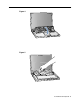
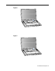
6. Release the keyboard by pulling down on the keyboard release tabs located to the left of the F1 and F9 keys (Figure 3), then lift the top portion of the keyboard up and toward the display to release the tabs that hold the bottom of the keyboard in place. 7. Flip over the keyboard and lay it on the palm rests and trackpad (Figure 4). 8. Touch the computer’s inside framework (a dull gray conductive composite material) to discharge any static electricity, as shown (Figure 5).
Figure 1 A B Figure 2 Figure 3 PowerBook G4 Keyboard - 3
Figure 4 Figure 5 PowerBook G4 Keyboard - 4
Figure 6 Figure 7 PowerBook G4 Keyboard - 5
Figure 8 Figure 9 PowerBook G4 Keyboard - 6
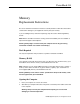
PowerBook G4 Memory Replacement Instructions Be sure to follow the instructions in this sheet carefully. Failure to follow these instructions could result in damage to your equipment and may void your warranty. If you are adding memory rather than replacing it, skip the section “Removing Memory Cards.” Note: Written and video instructions covering customer-installable parts are available at http://www.info.apple.com/installparts/.
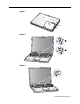
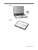
3. Close the computer and turn it over. Slide the battery compartment latch (Figure 1A) to the right to remove the battery (Figure 1B). Removing the battery will prevent you from accidentally turning on the computer. Warning: The internal components of your PowerBook may be hot. If you have been using your PowerBook, wait 30 minutes after shutting down your computer to let the internal components cool down before continuing. 4. Turn over the computer and raise the display so you can access the keyboard. 5.
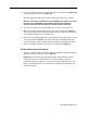
Removing Memory Cards Warning: When removing or installing a memory card, do not touch its gold connectors. Handle the card only by the edges. 1. To remove a memory card, locate the brackets that secure the card on both sides. Carefully spread the brackets apart until the card releases on each side (Figure 6). The card can then be pulled up and out. Note: If there is a memory card in the upper memory slot (Figure 6B), it must be removed before removing a card in the lower slot (Figure 6A).
Figure 1 A B Figure 2 Figure 3 PowerBook G4 Memory - 4
Figure 4 Figure 5 Figure 6 A B PowerBook G4 Memory - 5
Figure 7 A Figure 8 Figure 9 PowerBook G4 Memory - 6
Figure 10 Figure 11 PowerBook G4 Memory - 7
PowerBook G4 Modem Replacement Instructions Be sure to follow the instructions in this sheet carefully. Failure to follow these instructions could result in damage to your equipment and may void your warranty. Note: Written and video instructions covering customer-installable parts are available at http://www.info.apple.com/installparts/. Warning: Sharp edges can exist inside your computer and on any parts being removed or installed. Use caution to avoid injury.
6. Release the keyboard by pulling down on the keyboard release tabs located to the left of the F1 and F9 keys (Figure 3), then lift the top portion of the keyboard up and toward the display to release the tabs that hold the bottom of the keyboard in place. 7. Flip over the keyboard and lay it on the palm rests and trackpad (Figure 4). Removing the Modem 1. Touch the computer’s inside framework (a dull gray conductive composite material) to discharge any static electricity, as shown (Figure 5).
4. Install the hexnut screw (Figure 6A). The screw hole on the modem should be aligned with the screw flange; if not, the modem may not be properly attached to the logic board (see step 3). Note: It may be helpful to use a finger tip to hold the top of the screw straight and steady while turning the screw with a tool. Closing the Computer 1. Verify that the keyboard connector cable is securely attached to the logic board (Figure 13). 2.
Figure 1 A B Figure 2 Figure 3 PowerBook G4 Modem - 4
Figure 4 Figure 5 Figure 6 A PowerBook G4 Modem - 5
Figure 7 Figure 8 Figure 9 PowerBook G4 Modem - 6
Figure 10 Figure 11 Figure 12 PowerBook G4 Modem - 7
Figure 13 Figure 14 Figure 15 PowerBook G4 Modem - 8
PowerBook G4 Bottom Case Replacement Instructions Be sure to follow the instructions in this sheet carefully. Failure to follow these instructions could result in damage to your equipment and may void your warranty. Note: Written and video instructions covering customer-installable parts are available at http://www.info.apple.com/installparts/. Warning: Sharp edges can exist inside your computer and on any parts being removed or installed. Use caution to avoid injury.
5. Slide the battery compartment latch (Figure 2A) to remove the battery (Figure 2B). Make sure to return the battery latch fully to the right. Removing the battery will help you remove the bottom case and prevent you from accidentally turning on the computer. 6. Using a Phillips screwdriver, remove the eight screws that secure the bottom case to the PowerBook, in the order shown (Figure 3).
Installing the Bottom Case 1. To attach the bottom case, align the notches on the right and left sides of the case (some of these can be viewed through the battery opening). Then press down and toward you slightly to secure the case (Figure 7). Verify that the case lies flat and fits properly around the battery latch and that the alignment tab that protrudes on the underside of the bottom case (Figure 7A), has seated properly. The case edges should line up smoothly.
Figure 1 A B Figure 2 B A Figure 3 1 4 3 2 5 8 7 6 PowerBook G4 Bottom Case - 4
Figure 4 Figure 5 Figure 6 PowerBook G4 Bottom Case - 5
Figure 7 8 5 6 A 7 4 2 1 3 Figure 8 A B PowerBook G4 Bottom Case - 6
PowerBook G4 AirPort Card Replacement Instructions Be sure to follow the instructions in this sheet carefully. Failure to follow these instructions could result in damage to your equipment and may void your warranty. If you are adding an AirPort Card rather than replacing one, skip the section “Removing the AirPort Card.” Note: Written and video instructions covering customer-installable parts are available at http://www.info.apple.com/installparts/.
4. With the display open at an angle greater than 90 degrees, carefully flip the PowerBook over and lay it flat, fully on the table. Make sure the display hangs over the edge of the table and rests lightly on your lap (Figure 1B). 5. Slide the battery compartment latch (Figure 2A) to remove the battery (Figure 2B). Make sure to return the battery latch fully to the right. Removing the battery will help you remove the bottom case and prevent you from accidentally turning on the computer. 6.
Removing the AirPort Card 1. Pull back on the antenna clip (Figure 8A) to release the antenna cable connector (Figure 8B) and allow the card to rise up slightly, then pull the card from the AirPort connector (Figure 8D). Hold the AirPort Card with one hand and grasp the antenna cable connector with the other. While being careful not to strain the antenna cable (Figure 8C), firmly pull the connector straight out of the AirPort Card.
7. Fold the plastic tab (Figure 12F) on the AirPort Card over the top of the card. Note: The plastic tab must be folded over the card during the installation of the bottom case, otherwise you will not be able to securely attach the bottom case to the computer. Closing the Computer 1. To attach the bottom case, align the notches on the right and left sides of the case (some of these can be viewed through the battery opening). Then press down and toward you slightly to secure the case (Figure 13).
Figure 1 A B Figure 2 B A Figure 3 1 4 3 2 5 8 7 6 PowerBook G4 AirPort Card - 5
Figure 4 Figure 5 Figure 6 PowerBook G4 AirPort Card - 6
Figure 7 Figure 8 D C A B Figure 9 A C B PowerBook G4 AirPort Card - 7
Figure 10 B A Figure 11 A B Figure 12 E F D C B A PowerBook G4 AirPort Card - 8
Figure 13 8 5 6 A 7 4 2 1 3 Figure 14 A B PowerBook G4 AirPort Card - 9
PowerBook G4 Hard Drive Replacement Instructions Follow the instructions in this sheet carefully. Failure to follow these instructions could damage your equipment and void its warranty. Note: Written and video instructions covering customer-installable parts are available at http://www.info.apple.com/installparts/. Warning: Sharp edges can exist inside your computer and on any parts being removed or installed. Use caution to avoid injury. During this procedure, keep small parts away from children.
4. Place a towel or soft cloth on a table in front of you. (Figure 1A) The towel or cloth will protect the keyboard and display area of the PowerBook when you flip it over to remove the battery and bottom case. Make sure it covers an area large enough for your PowerBook and that it hangs over the edge of the table. 5. With the display open at an angle greater than 90 degrees, carefully flip the PowerBook over and lay it flat, fully on the table.
7. Use a Phillips screwdriver to remove the eight bottom case screws in the order shown. (Figure 3) Important: To avoid damaging the case, be careful that the screwdriver tip does not slip out of the screw head during removal. Figure 3 1 4 3 2 5 8 7 6 Note: In the following two steps you will disengage the left and right sides of the bottom case and then pivot it forward to remove. 8. Carefully slide the bottom case away from you. (Figure 4) Important: Do not push on the rubber feet of the bottom case.
9. Pivot the bottom case up as shown. (Figure 5) Figure 5 10. Touch the computer’s inside framework (a dull gray conductive composite material) to discharge any static electricity, as shown. (Figure 6) Important: To avoid electrostatic discharge damage, always ground yourself by touching the computer’s framework before you touch any parts or install any components inside the computer.
Removing the Installed Hard Drive 1. With your fingers, carefully pry up the hard drive flex cable connector (Figure 7A) at its sides to disconnect it from the logic board. You may need to pry one side, then the other, in a rocking motion. Figure 7 A 2. With a Torx T8 screwdriver, remove the two screws (Figure 8) that secure the hard drive to the mounting bracket and then gently remove the hard drive. Important: Do not pull on the flex cable or use the cable as a handle.
Installing the Replacement Hard Drive Warning: To avoid potential injury, avoid touching or brushing against the thin strip of metal that extends up from the hard drive mounting bracket (Figure 9A). Important: Avoid touching the optical drive as you perform this procedure. 1. With a Torx T8 screwdriver, remove the screw from the top of the hard drive mounting bracket. (Figure 9B) 2. Carefully lift the mounting bracket up (Figure 9C) and gently bend it around the first battery bay tab (Figure 9D).
3. Make sure that the screws (Figure 10A) and rubber stoppers (Figure 10B) are in place on the sides of the replacement drive. 4. Install the Mylar sheath (Figure 10C) so that it covers the bottom and left and right sides of the drive. The sheath is directional and must be installed in the direction that does not extend beyond the front of the drive. 5. Carefully install the flex cable to the hard drive, if needed, (Figure 10D). The connector is keyed to fit only one way. Figure 10 B C D A 6.
7. Lift the mounting bracket (Figure 12A) over the battery bay tab and lower it to its original position. Line up the rubber stoppers on the hard drive until they fully seat into the holes in the bracket. Note: To help with alignment, the Torx T8 screwdriver can be inserted into the screws on the hard drive through the holes in the mounting bracket. Important: Verify that the bottom of the mounting bracket clears and seats behind a thin metal ridge located along the bottom of the battery compartment.
Closing the Computer 1. To attach the bottom case, align the notches on the right and left sides of the case, then press down slightly to secure the case. Check the alignment of the eight screw holes to make sure the bottom case is properly positioned. Important: Make sure that the seams between the bottom case and the frame are closed. Check the outside edges and around the battery well. Verify that the alignment tab on the underside of the bottom case (Figure 14A) has seated, and the case lies flat. 2.
3. Replace the battery. (Figure 15) Important: Make sure that the battery locks securely into place and that the battery latch is slid all the way into the locked position. Figure 15 4. Turn the computer over. Look at the optical drive slot to make sure that the case is properly secured. If a gap exists below the slot, gently pull the bottom of the optical drive slot toward you until it clicks into place and the gap is removed.
5. Reconnect the power cord and any other cables that were connected, and restart your computer. Warning: Never turn on your computer unless all of its internal and external parts are in place and it is closed. Operating the computer when it is open or missing parts can damage your computer or cause injury. 6. Restore the data from your backup to the new drive. 7. Check the operation of the optical drive.
PowerBook G4 DVD-ROM Drive Replacement Instructions The following instructions explain how to replace the DVD-ROM drive in the PowerBook G4 computer. Tools • Soft towel or cloth, larger than the PowerBook • Black stick (or other nonconductive nylon or plastic tool) Preliminary Steps Before you begin, remove the following: • Battery • Keyboard • Bottom case © 2003 Apple Computer, Inc. All rights reserved.
Procedure 1. With the computer on a soft cloth, locate the adhesive dust cover, a black plastic sheet that holds the PMU and DVD ribbon cables in place. Warning: The adhesive dust cover adheres to the thin, plastic DVD drive sleeve. Removing the dust cover too quickly might cause the sleeve to tear, exposing the DVD drive mechanism. 2. Starting at one corner, slowly and carefully peel off the adhesive dust cover.
4. Warning: The drive is a sensitive device and should be handled carefully to avoid damage. Handle the drive only by the corners or the back end of the drive, as indicated by the safe areas shown below. Do not place anything on top of the drive nor press on the body of the drive. If mishandled, the alignment of the drive frame could be altered, resulting in issues with disk mounting, disk insertion, or disk ejection. 5.
6. Holding the corners on the left side of the drive, pull up on the DVD drive until it releases from the computer. Note: There are four rubber mounts (two on each side) on the DVD drive that are held by friction on the screws. Remove any that may have fallen off inside the computer. 7. Before installing the replacement drive, verify that the small, metal EMI clip, normally located between the PMU cable and the DVD cable, is securely attached to the frame rib.
8. Install the replacement DVD-ROM drive (noting the additional instructions below), and reassemble and test the computer. When reassembling the computer, verify that there are two screws with rubber mounts on both the right and left side of the drive. Note: The rubber mount at the front right corner of the drive is shorter than the other three rubber mounts.
PowerBook G4 PMU Card Replacement Instructions The following instructions explain how to replace the PMU (Power Management Unit) card in the PowerBook G4 computer. Tools • Soft towel or cloth, larger than the PowerBook • Black stick (or other nonconductive nylon or plastic tool) Preliminary Steps Before you begin, remove the following: • Battery • Keyboard • Bottom case • DVD-ROM drive © 2003 Apple Computer, Inc. All rights reserved.
Procedure Important: Some of the internal cables are held in place by transparent orange Kapton tape. Note the orientation of the tape before removing it, and reserve the tape to use again for the replacement PMU card connections. 1. Carefully peel away the tape so you can disconnect the backup battery connector from the PMU card. Important: When reassembling the computer, make sure the connected backup battery cable is routed at an approximate 90-degree angle, as shown.
2. Disconnect the ribbon cable at J1. 3. Disconnect the ribbon cable at J5. 4. From the left corner of the card, raise the metal clip out of the hole in the PMU card. Pivot the card clockwise slightly to free the PMU card from the metal clip and the metal tab at the side of the card. 5. Install the replacement PMU card, and reassemble and test the computer.
PowerBook G4 Backup Battery Replacement Instructions The following instructions explain how to replace the backup battery in the PowerBook G4 computer. Tools • Soft towel or cloth, larger than the PowerBook • Black stick (on other nonconductive nylon or plastic tool) Preliminary Steps Before you begin, remove the following: • Battery • Keyboard • Bottom case • DVD-ROM drive © 2003 Apple Computer, Inc. All rights reserved.
Procedure 1. Notice that the backup battery cable and the single, black wireless antenna cable are held in place by transparent orange Kapton tape. Important: When reassembling the computer, make sure the connected backup battery cable is routed at an approximate 90-degree angle, as shown. Note: When reassembling the computer, reuse the tape to secure the replacement backup battery cable and the wireless antenna cable. 2.
6. When positioning the replacement backup battery on the inner top case, make sure the battery fits within the ridged battery area of the inner top case, and the backup battery cable faces the PMU card, as shown below. 7. Install the replacement backup battery, and reassemble and test the computer.
PowerBook G4 Logic Board Replacement Instructions The following instructions explain how to replace the logic board in the PowerBook G4 computer. Tools • • • • Soft towel or cloth, larger than the PowerBook Torx T8 screwdriver Black stick (or other nonconductive plastic or nylon tool) Razor blade Note: To organize the screws you remove from the computer, use a tray with divided compartments (such as a plastic ice cube tray).
Procedure 1. From the keyboard opening, disconnect the three-pin fan connector. Fan Connector ® 2. Remove the Torx T8 screw that is closest to the PC card carrier. 3. Disconnect the PC Card ribbon cable connector and the six-pin keyed battery connector. Important: If the battery connector has not been disconnected before, the keyed connector may be tight. If necessary, use a black stick to loosen one side of the connector and then the other side.
4. Locate the small metal EMI clip that folds over the plastic rib by the DVD drive. Fold up and straighten the EMI clip. Note: When reassembling the computer, hold the EMI clip in place over the frame rib while carefully tilting up the computer so you can access the other end of the EMI clip. Through the keyboard opening, bend the clip down over the rib of the frame. Check both sides of the clip to ensure that it is held in place and is not interfering with the DVD drive connector or the PMU connector.
5. Important: With the bottom case removed, be careful when turning over the computer. Some components could become loose and fall out. Warning: The cables connected to the LVDS (low voltage data signal) connector are extremely delicate. Do not pull or pinch the LVDS cables. Warning: Be especially careful when working near cables that attach to the display. If any of these cables are damaged, the entire display module must be replaced. Turn over the computer so the display rests lightly in your lap.
6. Near the center of the logic board, disconnect the AirPort connector and the hard drive connector. 7. Remove the two identical Torx T8 screws, located near the center of the board. Note: When reassembling the computer, do not overtighten the screws.
8. At the right side of the board, as shown, disconnect • PMU connector • DVD drive connector • Two-pin power connector Note: If tape is covering the power connector and cable, carefully pull it out of the way. Place the tape aside for reuse on the replacement logic board. 9. Verify that the EMI clip—located between the DVD drive connector and the PMU connector— is loose and does not catch on the logic board.
10. Grasp the logic board near the AirPort Card carrier. Gently tilt up the board, being careful where it catches on the back panel ports, integral mesh liner, and the disconnected cables. If necessary, open the panel door and press on the ports to free the logic board from the back panel. Note: When reassembling the computer, make sure the replacement logic board ports align completely with the openings in the back panel.
Note: When positioning the replacement logic board into the computer, check that cables and connectors do not get caught under the board. Tilt the logic board toward the back panel, and place the following cables into the notches in the board: • Power cable (reapply tape over the power cable, if applicable) • Backlight cable • LVDS cable • Audio cable Power Connector Tape Notch 11. Remove existing memory cards from the logic board for installation on the replacement logic board. 12.
14. Check that the heat exchanger has two square thermal interface pads in place. If the pads are missing or damaged, replace them. 15. Important: If you have removed the logic board to access another part, and you will be placing the original logic board back in the computer, use a razor blade to gently scrape away any residual thermal transfer material from the heat exchanger and the microprocessor chip.
16. On the replacement logic board, center new thermal transfer material over the epoxy cap on the microprocessor chip. Press it into place. Thermal Transfer Material 17. Install the replacement logic board, and reassemble and test the computer.
PowerBook G4 Display Module Replacement Instructions The following instructions explain how to replace the display module on the PowerBook G4 computer. Warning: Make sure you carefully follow these instructions, especially when working near cables that attach to the replacement display module. If any of the cables are damaged, the entire display module must be replaced.
Procedure Important: With the bottom case removed, be careful when turning over the computer. Some components could become loose and fall out. 1. Open the computer to an approximate 45-degree angle, and stand it on a soft cloth with the clutch covers facing up. 2. Remove the four identical Torx T8 screws from the clutch covers (two screws on each clutch cover).
3. Close the computer, and use a black stick to pry off the two clutch covers. Important: When reassembling the computer, note that each clutch cover has a molded number centered inside it. When the computer is positioned upside down, as shown below, the left clutch cover is labeled "1"; the right clutch cover is labeled "2". Make sure the left and right clutch covers are placed correctly on the clutches.
4. Warning: Be especially careful when working near cables that attach to the display. If any of these cables are damaged, the entire display module must be replaced. Warning: At the left clutch, the wrapped cable connected to the LVDS (low voltage data signal) connector is extremely delicate. Do not pull or pinch the LVDS cable. Do not allow the screwdriver to touch the LVDS cable. Use a black stick to gently move aside the LVDS cable so you can access the two silver-colored screws.
5. At the right clutch, note the routing of the inverter cable (the black and pink wires). Without straining the inverter cable, gently move it aside so you can access the two silver-colored screws. 6. Remove the two identical silver-colored Phillips screws from the right clutch. (Do not remove the black screws.) 7. Remove the Kapton tape, and reserve it for the replacement display module. 8. Disconnect the inverter cable, and lift the inner clutch mount out of the way. 9.
10. Warning: The LVDS cable and connector are extremely delicate. Do not pull or pinch the LVDS cable or connector. On the left side, move the inner clutch mount out of the way, and thread the blueand-white power switch cable through the opening in the top case. 11. Warning: The LVDS cable and connector are extremely delicate. Do not pull or pinch the LVDS cable or connector. Carefully guide the LVDS cable through the hole by turning the LVDS connector sideways, as shown, to fit through the opening.
12. If necessary, press the computer latch on the front of the computer to release the display module from the top case. 13. The display module includes all three cables. 14. Install the replacement display module, and reassemble and test the computer. Important: When the replacement display module is installed, and before the clutch covers are installed, test that the display is seated properly. With the computer upright and closed, press the computer latch.
PowerBook G4 PC Card Cage Replacement Instructions The following instructions explain how to replace the PC card cage in the PowerBook G4 computer. Tools • Soft towel or cloth larger than the PowerBook • Torx T8 screwdriver Note: To organize the screws you remove from the computer, use a tray with divided compartments (such as a plastic ice cube tray).
Procedure 1. To protect the display from scratches, place a sheet of paper between the display face and the top case. (Make sure the paper does not block the computer latch.) With the computer on a soft cloth, remove the two screws that attach the PC card cage to the rib frame. (The longer screw is next to the battery connector.) 2. Lift out the PC card cage, being careful where it can catch on the PC card eject button. 3. Install the replacement PC card cage, and reassemble and test the computer.
PowerBook G4 Rib Frame and Heat Exchanger Replacement Instructions The following instructions explain how to replace the rib frame and the heat exchanger in the PowerBook G4 computer. Tools • Soft towel or cloth larger than the PowerBook • Torx T8 screwdriver • Torx T6 screwdriver Note: To organize the screws you remove from the computer, use a tray with divided compartments (such as a plastic ice cube tray).
Procedure 1. With the computer on a soft cloth, remove the four identical screws from the top case. 2. To protect the display from scratches, place a sheet of paper between the display face and the top case. (Make sure the paper does not block the computer latch.) Close the computer 3. Open the I/O door, and remove the four identical Torx T6 screws. 4. Turn over the computer, and remove the four identical black screws.
5. Warning: When removing the rib frame and heat exchanger, make sure the heat exchanger does not fall onto the display. Support both the rib frame and the heat exchanger as you lift them out. Note: The heat exchanger is loosely attached to the rib frame at two slots. Notice that the heat exchanger fits under the rib frame on the left, and over the rib frame on the right, as shown below. .
6. Install the replacement rib frame and/or heat exchanger, and reassemble and test the computer.
PowerBook G4 Inverter Board Replacement Instructions The following instructions explain how to replace the inverter board in the PowerBook G4 computer. Tools • • • • Soft towel or cloth larger than the PowerBook Torx T8 screwdriver #1 Phillips screwdriver Black stick (or other nonconductive plastic or nylon tool) Note: To organize the screws you remove from the computer, use a tray with divided compartments (such as a plastic ice cube tray).
Procedure 1. With the computer on a soft cloth, remove the two identical screws from the clutch cover that is next to the power adapter port, as shown. 2. Use a black stick to remove the clutch cover. 3. At the clutch, note the routing of the inverter cable (the black and pink wires). Without straining the inverter cable, gently remove the Kapton tape from the inverter cable. Disconnect the inverter cable from the inverter board. 4.
5. Lift the inner clutch mount out of the way. 6. Tilt up the inverter board, and disconnect the PMU cable. Lift out the inverter board. 7. Install the replacement inverter board, and reassemble and test the computer.
PowerBook G4 Top Case Replacement Instructions The following instructions explain how to replace the top case in the PowerBook G4 computer.
Procedure 1. With the top case on a soft cloth, notice the placement of the transparent, orange Kapton tape and the routing of the PMU ribbon cable. PMU Ribbon Cable 2. Use a black stick to peel off the Kapton tape from the PMU ribbon cable. Reserve the ribbon cable for the replacement top case.
3. Before installing the replacement top case, make sure it includes the following: • Fan (heatstaked to top case) • Speaker set and cables • Door at back panel • Mesh liner at ports • Inner clutch mounts (two) • Power button and board (heatstaked to top case) • AirPort antenna cable • Trackpad assembly with board and cable 4. Important: Make sure you transfer the original serial number label from the old top case to the serial number panel on the replacement top case.
PowerBook G4 Screw Reference Sheet This sheet shows the types of screws used in the PowerBook G4 computer. To see where the screws are located in the computer, refer to "PowerBook G4 Screw Locator." Modem, magnetic 1 @ 7 mm Bottom Case 8 @ 8 mm Hard Drive 4 @ 5 mm (black) PC Card Cage 1 @ 6.5 mm PC Card Cage 1 @ 4.5 mm Rib Frame 4 @ 4.5 mm Logic Board 3 @ 4.5 mm Rib Frame, Clutch, 4 @ 5.25 mm Logic Board 1 @ 4.5 mm Rib Frame, Clutch, 3 @ 16.5 mm Logic Board 2 @ 8 mm Rib Frame, Clutch, 1 @ 16.
PowerBook G4 Screw Locator - 1 of 4 Modem Replacement One 5 mm magnetic hex nut, 7 mm long Bottom Case Replacement Eight identical Phillips, 8 mm long Hard Drive Replacement Four identical (black) Torx T8, 5 mm long © 2003 Apple Computer, Inc. All rights reserved.
PowerBook G4 Screw Locator - 2 of 4 Logic Board Replacement B (A) - Two identical Torx T8, 4.5 mm long A (B) - One Torx T8, 4.5 mm long A Two identical Torx T8, 8 mm long PC Card Replacement (C) - One Torx T8, 4.5 mm long (D) - One Torx T8, 6.
PowerBook G4 Screw Locator - 3 of 4 Rib Frame and Heat Exchanger Replacement Four identical Torx T8, 4.5 mm long Four identical Torx T8, 5.25 mm long E (E) - One Phillips, 16.5 mm long (F) - One Phillips, 16.5 mm long Two identical Phillips, 16.
PowerBook G4 Screw Locator - 4 of 4 Four identical Torx T6, 4.5 mm long Four identical (Black) Torx T8, 9.
Service Source Troubleshooting PowerBook G4 © 2003 Apple Computer, Inc. All rights reserved.
TITLE PowerBook G4: Troubleshooting Document Writer: Huckabone, Michael Created: 2001-7-20 Modified: 2001-7-20 TOPIC This is a PDF document of recent troubleshooting articles for Apple Specialists, Apple-Authorized Self-Servicing Providers and Internal Use.
Beeps Are Heard at Startup (one to four beeps) Dialog Box "Built-in Memory Test Has Detected an Error" Comes Up On Startup Display When displaying a single color over the screen area, the LCD panel shows one or more pixels that are not properly lit
TITLE PowerBook G4: AirPort Card Not Recognized Writer: Huckabone, Michael Created: 2001-7-20 Modified: 2001-8-17 TOPIC AirPort Card not recognized. DISCUSSION *RESTRICTED: Apple Specialists/Apple-Authorized Self-Servicing Providers * Internal Use Only Troubleshooting Procedure The steps to solve a symptom are listed sequentially. You might not need to perform every step before the symptom is solved. Start with the first step, and then test for the symptom.
Support Site Index | Export Compliance Contact Us | Privacy Notice Copyright © 2001 Apple Computer, Inc. All rights reserved.
TITLE PowerBook G4: Battery Will Not Eject Writer: Huckabone, Michael Created: 2001-7-20 Modified: 2001-8-17 TOPIC Releasing the battery latch does not eject the battery. DISCUSSION *RESTRICTED: Apple Specialists/Apple-Authorized Self-Servicing Providers * Internal Use Only Troubleshooting Procedure The steps to solve a symptom are listed sequentially. You might not need to perform every step before the symptom is solved. Start with the first step, and then test for the symptom.
Support Site Index | Export Compliance Contact Us | Privacy Notice Copyright © 2001 Apple Computer, Inc. All rights reserved.
TITLE PowerBook G4: Hard Drive Will Not Initialize Writer: Huckabone, Michael Created: 2001-7-20 Modified: 2001-8-17 TOPIC Hard drive will not initialize DISCUSSION *RESTRICTED: Apple Specialists/Apple-Authorized Self-Servicing Providers * Internal Use Only Troubleshooting Procedure The steps to solve a symptom are listed sequentially. You might not need to perform every step before the symptom is solved. Start with the first step, and then test for the symptom.
Support Site Index | Export Compliance Contact Us | Privacy Notice Copyright © 2001 Apple Computer, Inc. All rights reserved.
TITLE PowerBook G4: No Modem Dial Tone Writer: Huckabone, Michael Created: 2001-7-20 Modified: 2001-8-17 TOPIC No modem dial tone. DISCUSSION *RESTRICTED: Apple Specialists/Apple-Authorized Self-Servicing Providers * Internal Use Only Troubleshooting Procedure The steps to solve a symptom are listed sequentially. You might not need to perform every step before the symptom is solved. Start with the first step, and then test for the symptom.
Category: Sub Category: Keywords: Contributor: Process Owner: PowerBook G4 Hardware Troubleshooting kpbook kssts hts Support Site Index | Export Compliance Contact Us | Privacy Notice Copyright © 2001 Apple Computer, Inc. All rights reserved.
TITLE PowerBook G4: DVD Disc Icon Does Not Show Up On Desktop, Or A Dialog Box Appears To Initialize Disc Writer: Huckabone, Michael Created: 2001-7-20 Modified: 2001-8-17 TOPIC DVD disc icon does not show up on desktop, or a dialog box appears to initialize disc. DISCUSSION *RESTRICTED: Apple Specialists/Apple-Authorized Self-Servicing Providers * Internal Use Only Troubleshooting Procedure The steps to solve a symptom are listed sequentially.
Support Site Index | Export Compliance Contact Us | Privacy Notice Copyright © 2001 Apple Computer, Inc. All rights reserved.
TITLE PowerBook G4: PC Card Will Not Insert Writer: Huckabone, Michael Created: 2001-7-20 Modified: 2001-8-17 TOPIC PC Card will not insert into the PC Card slot. DISCUSSION *RESTRICTED: Apple Specialists/Apple-Authorized Self-Servicing Providers * Internal Use Only Troubleshooting Procedure The steps to solve a symptom are listed sequentially. You might not need to perform every step before the symptom is solved. Start with the first step, and then test for the symptom.
8. Replace Card Cage, PCMCIA assembly. Document Information Product Area: PowerBook G4 Category: PowerBook G4 Hardware Sub Category: Troubleshooting Keywords: kpbook kssts hts Contributor: Process Owner: Support Site Index | Export Compliance Contact Us | Privacy Notice Copyright © 2001 Apple Computer, Inc. All rights reserved.
TITLE PowerBook G4: No Sound And Sound Control Panel Indicates An External Device Is Plugged In Writer: Huckabone, Michael Created: 2001-7-20 Modified: 2001-8-17 TOPIC No sound heard and the Speakers section of the Sound control panel indicates that an exteranal device is plugged in (to the headphone jack or USB ports). DISCUSSION *RESTRICTED: Apple Specialists/Apple-Authorized Self-Servicing Providers * Internal Use Only Troubleshooting Procedure The steps to solve a symptom are listed sequentially.
4. Replace logic board. Document Information Product Area: PowerBook G4 Category: PowerBook G4 Hardware Sub Category: Troubleshooting Keywords: kpbook kssts hts Contributor: Process Owner: Support Site Index | Export Compliance Contact Us | Privacy Notice Copyright © 2001 Apple Computer, Inc. All rights reserved.
TITLE PowerBook G4: No Display, Or Dim Display, But Computer Appears To Operate Correctly Writer: Huckabone, Michael Created: 2001-7-20 Modified: 2001-8-17 TOPIC No display, or dim display, but computer appears to operate correctly. DISCUSSION *RESTRICTED: Apple Specialists/Apple-Authorized Self-Servicing Providers * Internal Use Only Troubleshooting Procedure The steps to solve a symptom are listed sequentially. You might not need to perform every step before the symptom is solved.
Document Information Product Area: PowerBook G4 Category: PowerBook G4 Hardware Sub Category: Troubleshooting Keywords: kpbook kssts hts Contributor: Process Owner: Support Site Index | Export Compliance Contact Us | Privacy Notice Copyright © 2001 Apple Computer, Inc. All rights reserved.
TITLE PowerBook G4: No Video On External Device Connected Via S-Video Port Writer: Huckabone, Michael Created: 2001-7-20 Modified: 2001-8-17 TOPIC Computer appears to work, but no video on external device connected to the TV out port (S-video out port). DISCUSSION *RESTRICTED: Apple Specialists/Apple-Authorized Self-Servicing Providers * Internal Use Only Troubleshooting Procedure The steps to solve a symptom are listed sequentially. You might not need to perform every step before the symptom is solved.
Support Site Index | Export Compliance Contact Us | Privacy Notice Copyright © 2001 Apple Computer, Inc. All rights reserved.
TITLE PowerBook G4: No Video On External Device Connected To External Monitor Port Writer: Huckabone, Michael Created: 2001-7-20 Modified: 2001-8-17 TOPIC No video on an external device connected to the External monitor port. DISCUSSION *RESTRICTED: Apple Specialists/Apple-Authorized Self-Servicing Providers * Internal Use Only Troubleshooting Procedure The steps to solve a symptom are listed sequentially. You might not need to perform every step before the symptom is solved.
Support Site Index | Export Compliance Contact Us | Privacy Notice Copyright © 2001 Apple Computer, Inc. All rights reserved.
TITLE PowerBook G4: Latch Not Working Writer: Huckabone, Michael Created: 2001-7-20 Modified: 2001-8-17 TOPIC The latching mechanism that holds the display closed is not working. DISCUSSION *RESTRICTED: Apple Specialists/Apple-Authorized Self-Servicing Providers * Internal Use Only Troubleshooting Procedure The steps to solve a symptom are listed sequentially. You might not need to perform every step before the symptom is solved. Start with the first step, and then test for the symptom.
Support Site Index | Export Compliance Contact Us | Privacy Notice Copyright © 2001 Apple Computer, Inc. All rights reserved.
TITLE PowerBook G4: Date And Time Resets All The Time Writer: Huckabone, Michael Created: 2001-7-20 Modified: 2001-8-17 TOPIC The Date and Time settings reset all the time. DISCUSSION *RESTRICTED: Apple Specialists/Apple-Authorized Self-Servicing Providers * Internal Use Only Troubleshooting Procedure The steps to solve a symptom are listed sequentially. You might not need to perform every step before the symptom is solved. Start with the first step, and then test for the symptom.
Document Information Product Area: PowerBook G4 Category: PowerBook G4 Hardware Sub Category: Troubleshooting Keywords: kpbook kssts hts Contributor: Process Owner: Support Site Index | Export Compliance Contact Us | Privacy Notice Copyright © 2001 Apple Computer, Inc. All rights reserved.
TITLE PowerBook G4: -3278 Error Writer: Huckabone, Michael Created: 2001-7-20 Modified: 2001-8-17 TOPIC AirPort Card installed and received a -3278 error. DISCUSSION *RESTRICTED: Apple Specialists/Apple-Authorized Self-Servicing Providers * Internal Use Only Troubleshooting Procedure The steps to solve a symptom are listed sequentially. You might not need to perform every step before the symptom is solved. Start with the first step, and then test for the symptom.
Support Site Index | Export Compliance Contact Us | Privacy Notice Copyright © 2001 Apple Computer, Inc. All rights reserved.
TITLE PowerBook G4: Microphone Not Working Writer: Huckabone, Michael Created: 2001-7-20 Modified: 2001-8-17 TOPIC The microphone is not working. DISCUSSION *RESTRICTED: Apple Specialists/Apple-Authorized Self-Servicing Providers * Internal Use Only Troubleshooting Procedure The steps to solve a symptom are listed sequentially. You might not need to perform every step before the symptom is solved. Start with the first step, and then test for the symptom.
Support Site Index | Export Compliance Contact Us | Privacy Notice Copyright © 2001 Apple Computer, Inc. All rights reserved.
TITLE PowerBook G4: Beeps Are Heard at Startup (one to four beeps) Writer: Huckabone, Michael Created: 2001-7-20 Modified: 2001-8-17 TOPIC The computer automatically performs a power-on self test when it is turned on after being fully shut down (not a restart). This article explains what to do if one to four beeps are heard.
and restart. ■ If symptom does NOT repeat, replace RAM card. ■ If symptom repeats, replace RAM in lower RAM slot with known-good and compatible RAM card and restart. ■ If symptom repeats, replace logic board. 2. If a RAM card is NOT installed in the upper expansion slot, replace RAM in lower RAM slot with known-good and compatible RAM card and restart. ■ If symptom repeats, replace logic board. Four beeps: Bad checksum for the remainder of the boot ROM. The ROM (which is located on the logic board) is bad.
TITLE PowerBook G4: Dialog Box "Built-in Memory Test Has Detected an Error" Comes Up On Startup Writer: Huckabone, Michael Created: 2001-7-20 Modified: 2001-8-17 TOPIC During startup boot sequence and before reaching Finder, the following dialog box appears: "The built-in memory test has detected an error." DISCUSSION *RESTRICTED: Apple Specialists/Apple-Authorized Self-Servicing Providers * Internal Use Only Troubleshooting Procedure The steps to solve a symptom are listed sequentially.
Support Site Index | Export Compliance Contact Us | Privacy Notice Copyright © 2001 Apple Computer, Inc. All rights reserved.
Display When displaying a single color over the screen area, the LCD panel shows one or more pixels that are not properly lit To determine whether or not the display has an acceptable number of pixel anomalies, follow the steps below: 1. Set the display image to one of the following colors: all-white display, all-red display, all-green display, or all-blue display.
(red, green, and blue) that allow the image to be rendered in full color. Each subpixel has a corresponding transistor responsible for turning the subpixel on or off. There are typically millions of these subpixels on an LCD display. For example, the LCD panel used in the Apple Cinema HD display is made up of 2.3 million pixels and 6.9 million red, green, and blue subpixels.
Service Source Views PowerBook G4 © 2003 Apple Computer, Inc. All rights reserved.
Battery 661-2441 Bottom Case 922-4382 Hard Drive Rubber Stopper Hard Drive Screw 922-4502 Hard Drive Flex Cable 922-4378 AirPort Card 661-2219 Hard Drive 661-2443 (10 GB) 661-2444 (20 GB) 661-2445 (30 GB) DVD-ROM Drive 661-2538 DVD-ROM Drive Screw 922-4502 Logic Board 661-2536 (400 MHz) 661-2537 (500 MHz) RJ-11 Modem Port 922-5245 DVD-ROM Flex Cable 922-4379 DVD-ROM Drive Dust Cover 922-4608 Thermal Transfer Material 922-4593 SDRAM PC Card Cage 922-4594 Battery Eject Switch Assembly 922-4600 Heat