Service Source Power Mac G4 (Mirrored Drive Doors) Power Mac G4 (FW 800) Updated 22 February 2006 © 2003 Apple Computer, Inc. All rights reserved.
Service Source Take Apart Power Mac G4 (Mirrored Drive Doors) Power Mac G4 (FW 800) © 2003 Apple Computer, Inc. All rights reserved.
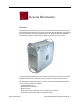
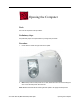
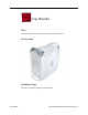
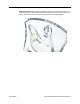
General Information Overview The identifying characteristics on the front of the Power Mac G4 (Mirrored Drive Doors), Power Mac G4 (Mirrored Drive Doors 2003), and Power Mac G4 (FW 800) computers are their top speaker and mirrored optical drive bezel. Like the Power Mac G4 (QuickSilver and QuickSilver 2002) computers, these models also have a silver-colored case.
Important: The Take Apart procedures are the same for all versions of the computers unless model differences are noted. Tools The following tools are required: • #2 Phillips screwdriver • #1 Phillips screwdriver • T-10 Torx driver or 2.5 mm Allen wrench • Small flat-blade screwdriver • Needlenose pliers Note: Magnetized tools are recommended to avoid dropping screws within the computer.
7. Put on an ESD wrist strap. 8. To avoid static electricity building back up in your body, do not walk around the room until after you have finished working and closed the computer. Operating the Computer Warning: In this computer the lower fan is in direct line with the heatsink. However, when the computer is open and the side panel is set down, the fan and heatsink are no longer in contact.
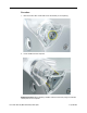
Opening the Computer Tools No tools are required for this procedure. Preliminary Steps No preliminary steps are required before you begin this procedure. Procedure 1. Lift the latch to unlock the right side access panel. 2. Note: Gently lower the side panel onto a clean, ESD-safe mat to avoid scratching the case. Lower the side panel until it lies flat. Note: Release the latch before returning the side panel to its upright closed position.
Top Handles Tools The only tool required for this procedure is a 2.5 mm Allen wrench. Part Location Preliminary Steps There are no preliminary steps for this procedure.
Procedure 1. Remove the two Allen screws that secure the handle you are replacing. 2. Lift the handle from the computer. Replacement Note: When replacing a handle, make sure the inner prongs fit inside the raised points on the computer.
Replacement Note: When replacing a handle, make sure you orient the handle so the three tiny bumps are near the lower edge of the handle.The handle won’t fit properly if it is turned upside down. The top front and top rear handles are interchangeable.
Top Panel Tools No tools are required for this procedure. Part Location Preliminary Steps Before you begin, remove the handles from the top front and top rear of the computer.
Procedure 1. Slide the top panel toward the front of the computer to unhook the six tabs. 2. Lift the top panel from the chassis.
Speaker Grill Tools The only tool required for this procedure is a small flat-blade screwdriver. Part Location Preliminary Steps There are no preliminary steps for this procedure.
Procedure 1. Insert the tip of a screwdriver into one of the openings in the speaker grill. Warning: To prevent damage to the speaker, do not insert the screwdriver too far. 2. Pry out the speaker grill. Replacement Note: Press the replacement speaker grill into the speaker opening.
Lower Supports Tools The only tool required for this procedure is a 2.5 mm Allen wrench. Part Location Preliminary Steps Before you begin, place the computer upside down on an ESD mat. Warning: When the computer is upside down or the lower supports are removed, the computer can be unstable.
Procedure 1. With the computer upside down, remove the two Allen screws securing the support to the computer. 2. Remove the support from the computer.
Lower Panel, Front Tools No tools are required for this procedure. Part Location Preliminary Steps Before you begin, remove the lower front support. Warning: When the computer is upside down or the lower support is removed, the computer can be unstable.
Procedure 1. Lift the lower front panel from the chassis. There are no screws holding this panel to the chassis; the front support holds it in place. 2. Important: Note the routing of the AirPort antenna cable. Carefully remove it from the notches in the lower front panel.
Lower Panel, Rear Tools No tools are required for this procedure. Part Location Preliminary Steps Before you begin, remove the lower rear support. Warning: When the computer is upside down or the lower support is removed, the computer can be unstable.
Procedure Lift the lower rear panel from the chassis. There are no screws holding this panel to the chassis; the rear support holds it in place.
Rear Vented Panel Tools The following tools are required for this procedure: • 2.5 mm Allen wrench • Flat-blade screwdriver Part Location Preliminary Steps Before you begin, remove the following: • Lower rear support • Lower rear panel • Top rear handle Warning: When the computer is upside down or the lower supports are removed, the computer can be unstable.
Procedure 1. With the computer positioned on its left side panel, remove the three Allen screws securing the rear vented panel to the computer. 2. Use a flat-blade screwdriver to pry out the tabs from the lower chassis.
3. Grasp the rear vented panel on both sides of the lockable cover latch, and forcefully pull off the rear vented panel.
Hard Drive Carrier, Back Tools The following tools are required for this procedure: • Magnetized #2 Phillips screwdriver. • Pliers Part Location Preliminary Steps Before you begin, open the side access panel.
Procedure 1. Using a Phillips screwdriver, remove the screw that attaches the carrier to the chassis. Note: On some production models, the screw is not present nor required. 2. Pull the left side lever forward, and slide the carrier up to release the mounting pegs on the back of the carrier from the chassis.
3. Rotate the carrier back from the chassis far enough to reach the drive cables. Disconnect the hard drive data and power cables (P2 and P3) from the hard drive(s). Note: You might need to use pliers to grasp and disconnect the power cable connector(s). 4. Remove the carrier and drive(s) from the computer. Replacement Note: Connect the cables to the drives before installing the carrier.
Replacement Note: Be sure to align the mounting pegs on the back of the carrier with the notches in the chassis. Then press the carrier in and down until the pegs engage and the left side lever clicks into place.
Hard Drive Carrier, Front Tools The only tool required for this procedure is a magnetized Phillips screwdriver. Part Location Preliminary Steps Before you begin, open the side access panel.
Procedure 1. Press down on the carrier’s right side lever. 2. Holding the lever down, slide the carrier forward and out of the computer. Warning: Be careful not to scrape any cables when sliding the carrier forward. Replacement Note: Align the center mounting peg on the top of the carrier with the center channel on the underside of the optical drive shelf. This center peg helps to guide the carrier.
Replacement Note: Before closing the side access panel, make sure the P4 and P5 power cable connectors are either attached to the hard drives or tucked inside the front hard drive carrier.
Hard Drive Tools The only tool required for this procedure is a Phillips screwdriver. Preliminary Steps Before you begin, do the following: • Open the side access panel. • Remove the hard drive carrier. Procedure 1. Remove the four mounting screws from the sides of the drive carrier. 2. Slide the drive forward out the front of the drive carrier.
ATA 100 Hard Drive Cable Tools No tools are required for this procedure. Preliminary Steps Before you begin, do the following: • Open the side access panel. • Remove the back hard drive carrier. Procedure 1. Open the cable clamp at the bottom of the chassis. 2. Disconnect the ATA 100 cable from the connector at J34 on the logic board.
Optical Drive Tools The only tool required for this procedure is a Phillips screwdriver. Part Location Preliminary Steps Before you begin, open the side access panel.
Procedure 1. Loosen the captive screw near the front panel board. 2. Remove the lower screw that secures the optical drive carrier to the chassis. 3. Slide the back panel off the carrier.
4. Slide the carrier back and rotate it so that you can reach the drive cables. 5. Disconnect the drive data and power cables (P6 and P7) from the back of the optical drive(s) and remove the carrier from the computer. 6. Remove the four mounting screws from the sides of the drive carrier. 7. Slide the drive forward out the front of the drive carrier.
Replacement Note: Before sliding the carrier back onto the optical drive shelf, make sure the power cable bundle at the side panel is routed in the recessed channel.
Replacement Note: When sliding the carrier back onto the optical drive shelf, make sure the latch on the underside of the carrier engages with the notch in the drive shelf. Replacement Note: Before sliding the rear panel back onto the carrier, make sure the top lip of the panel engages with the top edge of the drive carrier. Warning: Be careful not to pinch the power cable between the panel and the carrier.
Optical Drive Cable Tools No tools are required for this procedure. Preliminary Steps Before you begin, do the following: • Open the side access panel. • Remove the front hard drive carrier. • Remove the optical drive carrier. Procedure 1. Peel up the optical drive cable from the double-sided tape on the optical drive shelf.
2. Open the two cable clamps at the bottom of the chassis. 3. Disconnect the cable from the logic board and free the cable from the opening in the optical drive shelf.
Lower Fan Tools The only tool required for this procedure is a small flat-blade screwdriver. Part Location Preliminary Steps Before you begin, do the following: • Open the side access panel. • Remove the optical drive carrier.
Procedure 1. Disconnect the ribbon cable from the logic board and fold it back to expose the lower fan cable connector. 2. Using a small flat-blade screwdriver, gently lift up the locking tab on the lower fan cable and disconnect the cable from the logic board. Replacement Note: Route the fan cable under the ribbon cable and over the narrower flex cable, as shown.
3. Slide the fan straight up to disconnect it from the optical drive shelf, and remove the fan from the computer. Replacement Note: Align the fan with the three latches in the drive shelf and slide straight down until you feel the fan lock into place.
Replacement Note: On some production models, the fan includes a detachable finger guard. To transfer the finger guard to the replacement fan, use a needlenose pliers to remove the four plastic pegs. Then transfer the finger guard to the replacement fan.
Left Side Panel Tools The following tools are required for this procedure: • 2.5 mm Allen wrench • Needlenose pliers Part Location Preliminary Steps Before you begin, open the computer and remove the optical drive carrier.
Procedure 1. Remove the four 2.5 mm Allen screws on the side panel. 2. Using a needlenose pliers, squeeze the tabs (located beside the power supply cable bundle) to release the left side panel from the metal chassis. 3. Lift the left side panel from the chassis.
Front Panel Tools No tools are required for this procedure. Part Location Before you begin, open the computer and remove the following. • Handle at the top front of the computer • Support at the lower front of the computer • Speaker grill (if present) • Optical drive carrier Warning: When the lower support is removed, the computer can be unstable.
Procedure 1. Open the side access panel. Locate the four front panel tabs. 2. Carefully push the front panel tabs inward to release them from the chassis. 3. Pull the front panel off the chassis. 4. Press inward on the four tabs to remove the optical drive bezel from the front panel.
Power Supply Tools The following tools are required for this procedure: • #2 Phillips screwdriver • T-10 Torx driver Part Location Preliminary Steps Before you begin, do the following: • Open the side access panel. • Remove the optical drive carrier. • Remove the lower fan.
Procedure Warning: The power supply in this computer is a high-voltage component and should not be opened for any reason, even when the computer is off. 1. Use a T-10 Torx driver to remove the power supply screw from the back panel. 2. Remove the Phillips screw from the side panel.
3. Disconnect the power supply cables from all drives and from the logic board. Note: For the Power Mac G4 (FW 800) model of the computer, press and hold the tab on the black, plastic connector cover as you pull up the power connector from the board. Replacement Note: Install the connector cover over the power connector for the replacement power supply. 4. Release the power cable harness from the guides and route the harness out through the opening in the optical drive shelf.
5. Slide the power supply forward and remove the power supply and cable harness from the computer.
Speaker Tools The following tools are required for this procedure: • #2 Phillips screwdriver. • Small flat-blade screwdriver Part Location Preliminary Steps Before you begin, do the following: • Open the side access panel. • Remove the optical drive carrier.
Procedure 1. Using a small flat-blade screwdriver, lift up the locking tab on the speaker cable connector and disconnect the cable from the logic board. 2. Remove the cable from the cable guide. 3. Route the cable up and out through the opening in the optical drive shelf and out from under the speaker case.
4. Remove the speaker mounting screw. 5. Swing the speaker away from the chassis. Press in on the two latches on the right side of the speaker and release the speaker from the chassis.
6. Remove the speaker and cable from the computer. Replacement Note: With the replacement speaker attached to the chassis, make sure to route the speaker cable through the chassis guides, as shown.
Optical Drive Bezel Tools No tools are required for this procedure. Part Location Preliminary Steps Before you begin, do the following: • Open the side access panel. • Remove the optical drive carrier.
Procedure 1. Press in and release the top two latches on the inside of the optical drive bezel. 2. Press in and release the bottom two latches. 3. Remove the bezel from the computer.
Front Panel Board Tools The following tools are required for this procedure: • #2 Phillips screwdriver • Small flat-blade screwdriver • Needlenose pliers Part Location Preliminary Steps Before you begin, do the following: • Open the side access panel. • Remove the optical drive carrier. • Remove the optical drive bezel.
Procedure 1. Disconnect the front panel board cable from the front panel board. 2. Using a small flat-blade screwdriver, pry up the two black plastic pegs and then the two black plastic peg holders from the top of the front panel board. 3. Using a #2 Phillips screwdriver, remove the front panel board mounting screw. 4. Remove the front panel board through the front opening in the computer.
Replacement Note: When replacing the black plastic peg holders, use needlenose pliers to compress the holders so they will fit into the holes in the top of the front panel board.
Front Panel Board Cable Tools No tools are required for this procedure. Part Location Preliminary Steps Before you begin, do the following: • Open the side access panel. • Remove the front hard drive carrier. • Remove the optical drive carrier. • Loosen the speaker cable.
Procedure 1. Disconnect the front panel board cable from the front panel board. 2. Peel the front panel board cable from the recessed channel in the side chassis and route the cable through the opening in the optical drive shelf.
3. Open the two cable clamps at the bottom of the chassis and disconnect the front panel board connector from the logic board.
Optical Fan Tools The following tools are required for this procedure: • #2 Phillips screwdriver • Small flat-blade screwdriver Part Location Preliminary Steps Before you begin, open the side access panel.
Procedure 1. Using a small flat-blade screwdriver, gently lift up the locking tab on the optical fan cable and disconnect the cable from the logic board. 2. Remove the two Phillips screws from the fan baffle.
3. Slide the fan baffle forward to clear the two pegs, and lift the fan baffle off of the fan. 4. Pull the fan straight up to remove it from the two pegs. Route the fan cable under the surrounding foam wall. Replacement Note: If the foam wall is damaged, replace it by peeling off the old foam and cleaning the chassis surface with an alcohol wipe. Then apply the new foam wall to the chassis.
DIMMs Tools No tools are required for this procedure. Part Location Preliminary Steps Before you begin, do the following: • Open the side access panel. • Remove the heatsink if the DIMM is in the slot nearest the heatsink. (Note: The DIMM nearest the heatsink can be removed with the heatsink in place; however the fit is tight.
Procedure 1. Push down the ejectors on the DIMM slot. 2. Holding the DIMM by both top corners, lift it straight up out of the slot. Warning: When removing or installing the DIMM, handle it only by the edges. Do not touch its connectors. Lift the DIMM straight up from the connector to remove it, and insert it straight down into the connector to install it. Do not rock the DIMM from side to side. Replacement Note: The DIMM is designed to fit into the slot only one way.
Modem Tools The only tool required for this procedure is a Phillips screwdriver. Part Location Preliminary Steps Before you begin, open the side access panel.
Procedure 1. Using a Phillips screwdriver, remove the modem’s two mounting screws. 2. Lift the modem straight up a short distance to disconnect it from the logic board. 3. Disconnect the modem cable from the modem. 4. Remove the modem from the computer.
AirPort Card Note: This section applies to the Power Mac G4 (MIrrored Drive Doors) computer only. If you are replacing an AirPort Extreme Card—the smaller card—go to the next section. Tools No tools are required for this procedure. Part Location Preliminary Steps Before you begin, open the side access panel.
Procedure 1. Detach the coaxial antenna wire from the port on the end of the AirPort Card. 2. Pull the clear plastic tab on the AirPort Card to disconnect the card from the connector on the logic board.
Note: If you are not replacing the AirPort Card, stow the antenna wire on the side of the PCI card guide, being careful not to bend or crimp the wire tightly. Warning: Handle the AirPort antenna with care. Due to the cable routing through the chassis panels, an AirPort antenna can be replaced only by ordering a new computer enclosure.
AirPort Extreme Card Note: This section applies to the Power Mac G4 (FW 800) computer only. If you are replacing the original AirPort Card— the larger card—go to the previous section. Tools No tools are required for this procedure. Part Location Preliminary Steps Before you begin, open the side access panel.
Procedure 1. Detach the coaxial antenna wire from the port on the end of the AirPort Extreme Card. 2. Pull the clear plastic tab on the card to disconnect the card from the connector on the logic board.
Note: If you are not replacing the AirPort Extreme Card, stow the antenna wire on the side of the card guide, being careful not to bend or crimp the wire tightly. Warning: Handle the AirPort antenna with care. Due to the cable routing through the chassis panels, an AirPort antenna can be replaced only by ordering a new computer enclosure.
Bluetooth Note: This section applies to the Power Mac G4 (FW 800) computer only. Tools No tools are required for this procedure. Part Location Preliminary Steps Before you begin, open the side access panel.
Procedure 1. Holding the edges of the bluetooth board, pull the board straight up to disconnect it from the logic board. 2. Turn over the board and pull the round connector off the board.
Note: If you are not replacing Bluetooth, stow the antenna wire on the side of the PCI card guide, being careful not to bend or crimp the wire tightly.
Video Card Tools The only tool required for this procedure is a Phillips screwdriver. Part Location Preliminary Steps Before you begin, open the side access panel.
Procedure 1. Using a Phillips screwdriver, remove the video card mounting screw. 2. Gently hold back the clip on the video card connector to release the card. 3. Pull the card straight up, and remove it from the computer.
Replacement Note: Install an AGP card in slot 1 only. Install PCI cards in the slots labeled PCI 2, 3, 4, and 5. Warning: Cables with large connectors may interfere with the enclosure in the PCI slot numbered 5, making it difficult to close the door and potentially causing damage to the PCI card. If this is the case, rearrange the cards in the slots. You may also connect the cable after the enclosure door is shut, but be sure to remove the cable before opening the door again.
SCSI Card Note: This section applies to the Power Mac G4 (MIrrored Drive Doors) computer only. For the Power Mac G4 (FW 800) computer, the SCSI card is offered only as a third-party option, so refer to the third-party vendor for replacement of the card. Tools The only tool required for this procedure is a Phillips screwdriver. Part Location Preliminary Steps Before you begin, open the side access panel.
Procedure 1. Disconnect the SCSI cable from the SCSI card. 2. Remove the SCSI card mounting screw.
3. Lift up the SCSI card from the slot on the logic board.
SCSI Cable Note: This section applies to the Power Mac G4 (MIrrored Drive Doors) computer only. For the Power Mac G4 (FW 800) computer, the SCSI cable is offered only as a third-party option, so refer to the third-party vendor for replacement of the cable. Tools The only tool required for this procedure is a Phillips screwdriver. Part Location Preliminary Steps Before you begin, open the side access panel.
Procedure 1. Disconnect the SCSI cable from the SCSI card. 2. Disconnect the SCSI cable from the hard drives at the front and back hard drive carriers. 3. Disconnect the SCSI cable from the SCSI terminator at the bottom of the chassis.
Battery Tools No tools are required for this procedure. Part Location Preliminary Steps Before you begin, do the following: • Open the side access panel. • Remove the video card if a full-length video card extends over the battery.
Procedure 1. Note the orientation of the battery’s positive (+) end. 2. Remove the battery from its holder. Note: You may first need to spread the two tabs on the holder slightly apart to release the battery. Note: When replacing the battery, make sure the positive (+) end of the battery aligns with the + symbol on the battery holder.
Heatsink Note: This procedure is the same for both of the Power Mac G4 models, except for the heatsink appearance and screws. Tools The following tools are required for this procedure: • #1 Phillips screwdriver • #2 Phillips screwdriver Part Location Preliminary Steps Before you begin, open the side access panel.
Procedure 1.
Power Mac G4 (FW 800): • four 11-mm long #2 Phillips screws at heatsink Power Mac G4 (FW 800), Best Configuration: • four 11-mm long #2 Phillips screws at heatsink Heatsink Power Mac G4 (Mirror/FW 800) Take Apart - 89
2. Lift the heatsink straight up and remove it from the computer. Power Mac G4 (FW 800), Best Configuration: Warning: Handle the heatsink with care. Do not touch the underside of the heatsink. The solder joints at the heatsink coils are delicate and might be warm.
Note: Whenever you remove the heatsink, you must clean the heatsink base and add new thermal grease to the chips on the processor, as follows: • Use a clean pad to carefully remove the existing thermal grease from both chips. • Apply a 3-mm round dot of thermal grease on the center of both chips. • Use an alcohol pad to gently clean and dry the underside of the heatsink. • Ensure the heatsink is level as you CAREFULLY place it on the processor.
Power Mac G4 (FW 800): Replacement Note: If you are replacing the heatsink in the Power Mac G4 (FW 800) model, remove the two #2 Phillips screws at the heatsink bracket, and transfer the bracket to the replacement heatsink.
Power Mac G4 (FW 800), Best Configuration: Replacement Note: If you are replacing the heatsink in the Best configuration of the Power Mac G4 (FW 800) model, remove the two #2 Phillips screws at the heatsink bracket, and transfer the bracket to the replacement heatsink. (Refer to previous page.
Processor Tools No tools are required for this procedure. Part Location Preliminary Steps Before you begin, do the following: • Open the side access panel. • Remove the heatsink. • Remove the thermal grease (refer to Heatsink procedure).
Procedure 1. Grasp the processor by the edges and lift slightly to disconnect it from the logic board. 2. Slide the processor toward the back panel and then lift the processor up and out of the computer, being careful to clear the two mounting pegs. Before Replacing the Processor Important: Apple has determined a compatibility issue between the processor and certain fabrication levels of the logic board on some Power Mac Server G4 (Mirrored Drive Doors) and Power Mac G4 (Mirrored Drive Doors) products.
Processor Stiffener Tools No tools are required for this procedure. Part Location Preliminary Steps Before you begin, do the following: • Open the side access panel. • Remove the heatsink. • Remove the processor.
Procedure 1. Lift the processor stiffener straight up off the two mounting pegs. 2. Remove the stiffener from the computer.
Logic Board Note: This procedure pictures the Power Mac G4 (MIrrored Drive Doors) computer. Although the logic board in the Power Mac G4 (FW 800) model has a somewhat different shape, the steps are the same. Tools The only tool required for this procedure is a Phillips screwdriver. Part Location Preliminary Steps Before you begin, open the computer and remove the following.
• • • • • • • SCSI card (if present) Modem (if present) AirPort Card (if present) Bluetooth (if present) Heatsink Processor Processor stiffener Note: The replacement logic board does not include the heatsink, processor, processor stiffener, memory DIMMs, modem, Airport Card, or PCI/AGP cards. You must transfer these modules from the original board to the new one. Procedure 1. Disconnect all cables to the logic board 2. Remove the logic board mounting screw.
3. Slide the logic board toward the front of the computer to clear the chassis hooks. 4. Lift up the end of the logic board nearest the front of the computer and remove the logic board. Note: Be careful that the logic board ports clear the openings in the back panel. Note: After installing a replacement logic board, be sure to transfer the processor stiffener, processor, heatsink, DIMMs, and any other cards to the new board.
I/O Panel Tools The following tools are required for this procedure: • 2.
• • • • • • AirPort Card (if present) Bluetooth (if present) Heatsink Processor Processor stiffener Logic board Procedure 1. Remove the two Allen screws from the I/O panel. 2. Remove the Phillips screw securing the access cover to the rear chassis. Remove the access cover.
3. Use a flat-blade screwdriver to pry up the hooked tabs from the slots in the chassis. Pull that end of the I/O panel forward. 4. From inside the chassis, pry up the two tabs near the modem filter board.
5. Remove the I/O panel from the chassis. Replacement Note: Before installing the replacement I/O panel, insert the I/O port liner into the panel.
Right Side Access Panel Tools The following tools are required for this procedure: • 2.
• • • • • • AirPort Card (if present) Bluetooth (if present) Heatsink Processor Processor stiffener Logic board Procedure 1. Remove the four 2.5 mm Allen screws on the side panel.
2. Open the side access panel. 3. Remove the two Phillips screws attaching the right side panel to the metal chassis. 4. Using needlenose pliers, squeeze the plastic tabs (protruding through the chassis), to release the right side panel from the metal chassis.
5. Remove the right side panel from the chassis. Replacement Note: When installing the replacement right side access panel, make sure the latch is closed, and the metal latch spring pin inside the chassis fits under the plastic latch tab, as shown.
Replacement Note: When installing the replacement right side access panel for the Power Mac G4 (FW 800) model, make sure the cables are routed as shown.
Modem Filter Board Tools The only tool required for this procedure is a Phillips screwdriver. Part Location Preliminary Steps Before you begin, open the computer and remove the following.
Procedure 1. Remove the mounting screw that secures the modem filter board to the back chassis. 2. Free the modem filter board cable from the guides in the chassis. 3. Swing the modem filter board out of the opening in the back chassis. Replacement Note: Install the two tiny tabs on the replacement modem filter board into the tiny slots on the back chassis. Then swing the board into place before securing the screw.
Service Source Troubleshooting Power Mac G4 (Mirrored Drive Doors) Power Mac G4 (FW 800) © 2003 Apple Computer, Inc. All rights reserved.
General Information What’s New Available Configurations: Power Mac G4 (FW 800) Configuration Good Better Best Bus Speed 133 MHz 167 MHz 167 MHz L3 cache 1 MB 1 MB per processor 2 MB per processor Memory 256 MB, DDR 266 MHz 256 MB, DDR 333 MHz 512 MB, DDR 333 MHz Processor 1 GHz Power PC G4 Dual 1.25 GHz Power PC G4 Dual 1.
Available Configurations: Power Mac G4 (Mirrored Drive Doors 2003) Configuration Bus Speed 167 MHz L3 cache 1 MB per processor Memory 256 MB, DDR 333 MHz Processor Uni 1.25 GHz Power PC G4 Optical Drive Combo Drive (DVD-ROM/CDRW) Cable-Select Drives Important: This computer works with ATA and ATAPI internal storage devices that are set for cable select mode. The cable select feature forces the device to set its ID as either master or slave based upon its position on the ATA/ATAPI cable.
• 64-bit wide, 184-pin module • unbuffered (do not use registered or buffered DRAM) • maximum height of 1.3 inches Important: DIMMs from older Macintosh computers are not compatible with this computer. Do not use older DIMMs even if they fit into the DIMM slots. Results of Mixing PC2100 and PC2700 RAM This section describes what happens if you install both PC2100 and PC2700 memory in either a 167 MHz or a 133 MHz system bus computer.
DVI monitor port, and an ADC monitor port. There is also one headphone jack on the front of the computer. For the Power Mac G4 (FW 800) model, there is a FireWire 800 port below the two FireWire 400 ports on the back panel. The computer can be used with DVI or ADC monitors. To connect the computer to a VGA monitor, use the DVI-to-VGA adapter that came with the computer. Note: For a diagram of the ports location, refer to the Views chapter.
PCI Slot Power Consumption Specification This table shows the power consumption of the PCI slots in the Power Mac G4 (Mirrored Drive Doors) computer. Device Expansion card (15 W) Expansion card (25 W) For 4 Hard Drives For 2 Optical Drives Voltage (volts) Current (amps) Power (watts) +5V 3A 15 W + 12 V 0.5 A 6W -12 V 0.1 A 1.2 W +3.3 V 4.5 A 15 W +5V 5A 25 W + 12 V 0.5 A 6W -12 V 0.1 A 1.2 W +3.3 V 7.6 A 25 W +5V 3.2 A 16 W + 12 V 2.4 A 29 W +5V 2.4 A 12 W + 12 V 1.
Ventilation Warning: To prevent the computer from overheating, do not block the ventilation openings in the back panel. Hard Drives In this computer, the thickness of the hard drives must not exceed one inch (2.5 cm). The computer can accommodate two internal Ultra ATA hard drives in each hard drive carrier, for a total of four drives. If the computer has one Ultra ATA drive installed, it sits in the rear drive carrier.
Before Replacing the Processor Important: Apple has determined a compatibility issue between the processor and certain fabrication levels of the logic board on some Power Mac Server G4 (Mirrored Drive Doors) and Power Mac G4 (Mirrored Drive Doors) products. Before ordering a replacement processor for those models, follow these steps: 1. Open the computer and check the fabrication number that is printed on the logic board.
Backside L3 Cache 2MB SRAM (Dual) Backside L3 Cache 2MB SRAM 4.1 u P-I3 I2C ROM 1.2 Cache 256KB 1.
Resetting the PMU on the Logic Board The PMU (Power Management Unit) is a microcontroller chip that controls all power functions for this computer. The PMU is a computer within a computer. Its function is to: • tell the computer to turn on, turn off, sleep, wake, idle, etc. • manage system resets from various commands. • maintain parameter RAM (PRAM). • manage the real-time clock. Important: Be very careful when handling the logic board.
Power Supply Verification To power on, the computer’s logic board requires a “trickle” power of +5V. If the system fails to power on, first reset the PMU. Then follow the procedure outlined below to determine whether the problem is related to the power supply. Note: To verify the power supply, you need a volt meter. When connecting the volt meter leads to specific pins, make sure the power supply remains securely plugged into its connector on the logic board.
the voltage again. If voltage is still not present, replace the power supply. If you do measure +5V on pin 1, the power supply is likely OK. Go to the next step for further verification. 4. Start up the computer by pressing the power button on the front panel. If the computer starts up normally, the power supply is OK. If the computer does not start up normally, go to the next step. 5. Check to see if the power supply fan is spinning. If the fan is not spinning, replace the power supply.
RAM and Processor Verification: Power-On Self Test A power-on self test in the computer’s ROM automatically runs whenever the computer is started up after being fully shut down (the test does not run if the computer is only restarted). If the test detects a problem, you will not hear a normal startup chime. Instead, the system will beep as explained below: • 1 beep: No RAM is installed or detected. • 2 beeps: Incompatible RAM types are installed. • 3 beeps: No RAM banks passed memory testing.
Symptom Charts How to Use the Symptom Charts The Symptom Charts included in this chapter will help you diagnose specific symptoms related to the product. Because cures are listed on the charts in the order of most likely solution, try the cures in the order presented. Verify whether or not the product continues to exhibit the symptom. If the symptom persists, try the next cure. Note: If a cure instructs you to replace a module, reinstall the original module before you proceed to the next cure.
Startup System is completely dead (no fan movement and power LED is not lit) 1. Verify the power outlet is good. 2. Replace the power cord. 3. Make sure the voltage switch on the back of the power supply is set to the correct voltage. 4. Reset the logic board. Refer to “Resetting the PMU on the Logic Board” in this chapter. 5. Check for trickle voltage on the power supply connector. Refer to “Power Supply Verification” in this chapter. If verification fails, replace the power supply. 6.
• If in Mac OS 9, remove any items from the Servers folder in the System Folder. If that does not work, of if you are starting up in Mac OS X, turn off the computer by holding down the power button. Then start up using the Software Install CD. • Insert the system software CD and start up while holding down the C key. (Make sure the Caps Lock key is not engaged.) • After the computer starts up, see the troubleshooting information in the onscreen help. Choose Mac Help from the Help menu.
computer wakes. 5. Make sure the display brightness and contrast are set properly. 6. Reset the PRAM by restarting the computer while holding down the Command, Option, P, and R keys until you hear the startup sound a second time. Then start up using the Software Install CD. System shuts down intermittently 1. Make sure the power cord is plugged in firmly. 2. Check the Energy Saver settings. 3. Check that the power source is turned on and the correct voltage is present. 4. Replace the power cord. 5.
System shuts down when using multiple FireWire devices and an Apple ADC 17" CRT display is connected The power requirements for multiple FireWire devices and the Apple ADC 17" CRT display may exceed the capacity of the power supply, causing it to shut the system down. To alleviate this problem, do the following: 1. Reduce the number of bus-powered FireWire devices 2. Use a power adapter with all FireWire devices 3.
Error Tones Note: Error tones occur before system software loads. Computer beeps once at startup One beep means that no RAM is installed or detected. 1. If no DIMM is present, install a known-good DIMM in the top slot and try again. 2. Reseat the DIMMs. 3. Replace the DIMMs one at a time and test until all bad DIMMs are replaced with known-good modules. 4. Check that the processor module is properly installed. 5. Replace the processor module. Refer to "Before Replacing the Processor" in this chapter. 6.
1. Replace the processor module. Refer to "Before Replacing the Processor" in this chapter. 2. Replace the logic board. Video Screen is black, but startup chime is present, drive operates, fan is running, and power LED is lit 1. Check video cable/card connections and connector pins. 2. Test with a known-good monitor. Replace the monitor, if necessary. 3. Remove all third-party devices. 4. Reseat the video card. 5. Clear parameter RAM.
5. If using more than one display, make sure primary display is connected to video card. 6. Reseat the processor module. 7. Replace the processor module. Refer to "Before Replacing the Processor" in this chapter. 8. Replace the logic board. Video is distorted 1. Make sure that the video card driver and firmware are updated to the most recent versions. 2. Refer to the adjustments section of the service manual or owner’s manual for the monitor. Adjust monitor as necessary. 3.
• a VGA monitor using a DVI-to-VGA adapter • a DVI-to-VGA adapter that does not have a monitor connected to it Update to the latest version of Mac OS X. To download and install an update via the automatic Software Update feature in Mac OS X, choose System Preferences from the Apple menu, choose Software Update from the View menu, then click Check Now. Any available updates will be listed in Software Update. Sound No sound from computer’s internal speaker 1. Disconnect any microphones or external speakers.
a second startup chime. 4. Reinstall system software. 5. Replace the Apple Pro Speakers. 6. Replace logic board.
Fan interference heard through headphones 1. Plug headphones directly to the sound output port on the front of the computer. 2. Connect all other audio devices to the sound output port at the rear of the computer. Note: If headphones are connected through audio devices, such as grounded speakers, or mixers, and these devices are connected to the headphone sound output port, you may hear fan interference through the headphones.
Hard Drive Single internal ATA drive does not spin; flashing question mark on screen 1. Check all cable connections to the hard drive. 2. Try another power connector on the power cable harness. If the power cable is defective, replace the power supply. 3. Replace the hard drive. If the problem is resolved, make sure the driver and system software are updated to the most recent versions. No internal SCSI drive icon appears on the desktop 1. Check that the drive is listed in Apple System Profiler.
No external SCSI drive icon appears on the desktop 1. Verify there are no duplicate SCSI device addresses. 2. Verify the total cable length does not exceed the maximum total cable length for the SCSI card. See Knowledge Base article 58204. 3. Reseat the SCSI cable going to the SCSI card. 4. Replace the terminator on the external SCSI device. 5. Reseat the SCSI card. 6. Replace the SCSI card. For the Power Mac G4 (FW 800) model, this is a third-party card that is not available from Apple. 7.
Optical Drive Optical drive tray won’t open 1. Before opening the computer, try the following: Note: When following the steps below make sure that there is power to the computer and to the Apple Pro Keyboard and Apple Pro Mouse. If in Mac OS 9.2, • Press the Eject key on Apple Pro Keyboard. • To open the second optical drive on a Power Mac G4 (Mirrored Drive Doors) computer, press Option-Eject on the Apple Pro Keyboard. • Open the Eject application found in the Eject Extras folder.
open the tray. • Choose a different operating system in the startup manager, and eject the CD using the steps above. • Insert a paper clip into the manual eject hole, which is located on the bottom right or left side of the drive (depending on the model), under the bezel. A paper clip inserted into this hole unlatches the drive. Next, bend the paper clip into a hook and put it under the drive's tray. You should be able to pull the tray out at this point.
Optical drive icon does not appear on the desktop 1. Check to see if the optical drive is listed in Apple System Profiler. If it is, go to step 2. If it is not, go to step 7. 2. Try using a known-good disc. 3. If there is a disc stuck in the tray, refer to the symptom "Unable to eject disc". 4. Turn off all third-party extensions. 5. Verify the firmware is the most recent version for that drive. Check Software Downloads for any current update. 6. Reinstall system software. 7.
4. Relaunch Finder. 5. Start up from the system installation CD or system restore CD that came with the computer. If the keyboard operates, reinstall system software. 6. Replace the keyboard. 7. Replace the logic board. USB printer does not operate 1. Verify that connections to the printer and computer are secure. 2. Switch the printer to a different USB port. If the printer operates correctly, the first port was bad. Replace the logic board.
FireWire Devices No external FireWire device icon appears on the desktop 1. Verify that the FireWire device is turned on and the FireWire cable is securely connected to the device and the computer. 2. If the device requires external power, make sure it is plugged in. 3. Check that the FireWire device is listed in Apple System Profiler. If it is, go to step 4. If it is not, go to step 5. 4. Check the FireWire device documentation to see if additional drivers are required.
Modem The internal modem is not recognized 1. Make sure the correct CCL and extension files are installed. 2. Reseat the modem and modem cable. 3. Reinstall the CCL and modem extension. If the problem persists, reinstall the system software. 4. Clear parameter RAM. Hold down Command-Option-P-R during startup until you hear a second startup chime. 5. Replace the modem. System reports a No Dial Tone error message 1. Verify the modem phone cable is securely connected at the computer and the wall jack. 2.
Modem is having trouble connecting to online site 1. International only: Use the Modem Country Selector utility to make sure the modem is set to the correct country. 2. The phone line may have too much noise. If the user has a second line, try that one. The user should contact the local phone company and request the line be checked. 3. Check to make sure the TCP/IP system preference or control panel is correctly configured for the user's internet service provider.
Modem disconnects after a period of time A timed disconnect setting is causing the modem to disconnect. Some internet service providers or software packages have a feature that will disconnect the user after a set period of time. Either increase this time setting or disable the feature if possible. Contact the internet service provider or network administrator for more information. User does not receive a required callback from a server 1.
Service Source Views Power Mac G4 (Mirrored Drive Doors) Power Mac G4 (FW 800) © 2003 Apple Computer, Inc. All rights reserved.
Exploded View: Covers Power Mac G4 (Mirror/FW 800) Views - 1
Exploded View: Power Mac G4 (Mirrored Drive Doors) 2 - Power Mac G4 (Mirror/FW 800) Views
Exploded View: Power Mac G4 (FW 800) Power Mac G4 (Mirror/FW 800) Views - 3
Exploded View: Power Mac G4 (Mirrored Drive Doors 2003) 4 - Power Mac G4 (Mirror/FW 800) Views
Logic Board Diagram: Power Mac G4 (Mirrored Drive Doors) and Power Mac G4 (Mirrored Drive Doors 2003) Power Mac G4 (Mirror/FW 800) Views - 5
Logic Board Diagram: Power Mac G4 (FW 800) 6 - Power Mac G4 (Mirror/FW 800) Views
Front View: Power Mac G4 (Mirrored Drive Doors/FW 800) Power Mac G4 (Mirror/FW 800) Views - 7
Back View: Power Mac G4 (Mirrored Drive Doors) and Power Mac G4 (Mirrored Drive Doors 2003) Back View: Power Mac G4 (FW 800) 8 - Power Mac G4 (Mirror/FW 800) Views