
User's Manual
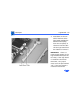
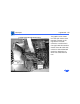
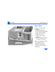
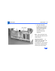
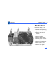
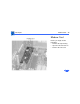
Table Of Contents
- Power Macintosh G3 Desktop
- Hot Issues
- Introduction
- Shared Logic Board
- Processor Module Vs. Card
- Power Supply Jumper
- Processor Module Jumper
- Warranty Sticker
- Power Supply Voltage Setting
- Voltage Regulator
- I/O Card
- ROM DIMM
- SDRAM DIMMs
- SGRAM Video Memory
- EIDE Bus Issue
- Master/Slave Support
- Ultra Wide SCSI Cable Routing
- DVD-ROM Disk Damage
- CD-ROM Ejection Problem
- HFS+ Formatted Drives
- Power-On Issue
- Basics
- Overview
- Data Buses
- Ultra Wide SCSI Card
- 10/100 BaseT Ethernet Card
- DVD-ROM Drive Technology
- FireWire Technology
- The Cuda Chip
- Resetting the Logic Board
- Sound
- Video Input and Output
- The DAV Connector
- Voltage Switch
- PowerPC G3 and Backside Cache
- SDRAM DIMMs
- SGRAM Video Memory
- DIMM Slots
- Peripheral Component Interconnect (PCI)
- Front View
- Rear View
- Internal Locator
- Logic Board
- Repair Strategy
- Warranty/AppleCare/ARIS
- G3 Design Information
- PowerPC Design Information
- Specifications
- Take Apart
- Top Housing
- Bezels
- Chassis Latch
- CD-ROM or DVD-ROM Drive
- Zip Drive
- Floppy Drive
- Drive Chassis
- Open/Remove Card Retainer Baffle
- Open Internal Chassis
- Hard Drive
- Drive Rails
- Power Supply
- Speaker
- Power Actuator
- Processor Module
- Battery
- PCI Cards
- Ultra Wide SCSI PCI Card
- FireWire PCI Card
- I/O Card
- Logic Board
- Rear Panel
- Bottom Chassis
- Modem Card
- Upgrades
- Troubleshooting
- Exploded View
- Screw Matrix
- Audio/Video Card Info
- Build-to-Order Info
- Hot Issues
Take Apart Logic Board - 85
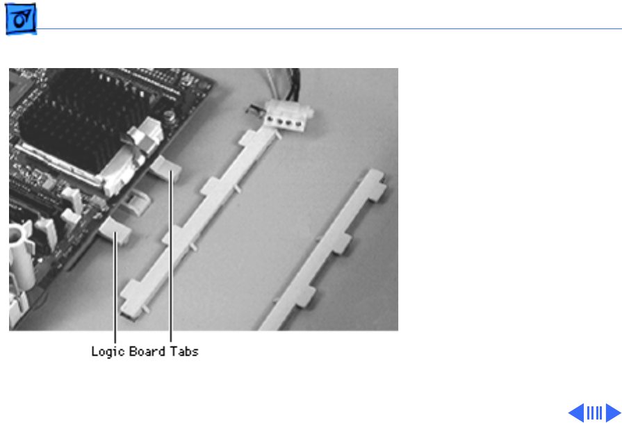
5 Press down on the two
tabs at the front of the
logic board and slide the
board forward (away
from the rear panel) to
release it from the tabs.
Lift the logic board from
the chassis to remove it.
IMPORTANT: There is a
power supply jumper on the
logic board at J28 (near the
PCI slots). If the logic board
is installed in the PM G3
Minitower, this jumper
must cover the pins marked
“PS”. If the logic board is
installed in the PM G3