
User's Manual
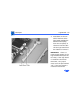
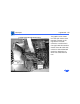
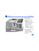
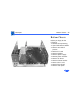
Table Of Contents
- Power Macintosh G3 Desktop
- Hot Issues
- Introduction
- Shared Logic Board
- Processor Module Vs. Card
- Power Supply Jumper
- Processor Module Jumper
- Warranty Sticker
- Power Supply Voltage Setting
- Voltage Regulator
- I/O Card
- ROM DIMM
- SDRAM DIMMs
- SGRAM Video Memory
- EIDE Bus Issue
- Master/Slave Support
- Ultra Wide SCSI Cable Routing
- DVD-ROM Disk Damage
- CD-ROM Ejection Problem
- HFS+ Formatted Drives
- Power-On Issue
- Basics
- Overview
- Data Buses
- Ultra Wide SCSI Card
- 10/100 BaseT Ethernet Card
- DVD-ROM Drive Technology
- FireWire Technology
- The Cuda Chip
- Resetting the Logic Board
- Sound
- Video Input and Output
- The DAV Connector
- Voltage Switch
- PowerPC G3 and Backside Cache
- SDRAM DIMMs
- SGRAM Video Memory
- DIMM Slots
- Peripheral Component Interconnect (PCI)
- Front View
- Rear View
- Internal Locator
- Logic Board
- Repair Strategy
- Warranty/AppleCare/ARIS
- G3 Design Information
- PowerPC Design Information
- Specifications
- Take Apart
- Top Housing
- Bezels
- Chassis Latch
- CD-ROM or DVD-ROM Drive
- Zip Drive
- Floppy Drive
- Drive Chassis
- Open/Remove Card Retainer Baffle
- Open Internal Chassis
- Hard Drive
- Drive Rails
- Power Supply
- Speaker
- Power Actuator
- Processor Module
- Battery
- PCI Cards
- Ultra Wide SCSI PCI Card
- FireWire PCI Card
- I/O Card
- Logic Board
- Rear Panel
- Bottom Chassis
- Modem Card
- Upgrades
- Troubleshooting
- Exploded View
- Screw Matrix
- Audio/Video Card Info
- Build-to-Order Info
- Hot Issues
Take Apart Rear Panel - 89
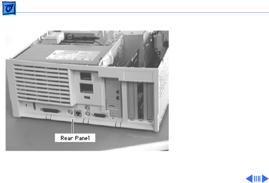
Rear Panel
Before you begin, do the
following:
• Remove top housing
• Open Card Retainer Baffle
• Open internal chassis
• Remove I/O card
• Remove PCI cards (if
present)
• Remove logic board (only
to replace rear panel)
Note: The rear panel covers
the back side of the
computer and provides
access to all the external
connectors.