
User's Manual


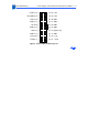
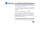

Table Of Contents
- Power Macintosh G3 Desktop
- Hot Issues
- Introduction
- Shared Logic Board
- Processor Module Vs. Card
- Power Supply Jumper
- Processor Module Jumper
- Warranty Sticker
- Power Supply Voltage Setting
- Voltage Regulator
- I/O Card
- ROM DIMM
- SDRAM DIMMs
- SGRAM Video Memory
- EIDE Bus Issue
- Master/Slave Support
- Ultra Wide SCSI Cable Routing
- DVD-ROM Disk Damage
- CD-ROM Ejection Problem
- HFS+ Formatted Drives
- Power-On Issue
- Basics
- Overview
- Data Buses
- Ultra Wide SCSI Card
- 10/100 BaseT Ethernet Card
- DVD-ROM Drive Technology
- FireWire Technology
- The Cuda Chip
- Resetting the Logic Board
- Sound
- Video Input and Output
- The DAV Connector
- Voltage Switch
- PowerPC G3 and Backside Cache
- SDRAM DIMMs
- SGRAM Video Memory
- DIMM Slots
- Peripheral Component Interconnect (PCI)
- Front View
- Rear View
- Internal Locator
- Logic Board
- Repair Strategy
- Warranty/AppleCare/ARIS
- G3 Design Information
- PowerPC Design Information
- Specifications
- Take Apart
- Top Housing
- Bezels
- Chassis Latch
- CD-ROM or DVD-ROM Drive
- Zip Drive
- Floppy Drive
- Drive Chassis
- Open/Remove Card Retainer Baffle
- Open Internal Chassis
- Hard Drive
- Drive Rails
- Power Supply
- Speaker
- Power Actuator
- Processor Module
- Battery
- PCI Cards
- Ultra Wide SCSI PCI Card
- FireWire PCI Card
- I/O Card
- Logic Board
- Rear Panel
- Bottom Chassis
- Modem Card
- Upgrades
- Troubleshooting
- Exploded View
- Screw Matrix
- Audio/Video Card Info
- Build-to-Order Info
- Hot Issues

Troubleshooting Power Supply Verification/Verification Procedure - 11
Power Supply Verification
The Power Macintosh G3 logic board requires a “trickle” power
of +5V in order to power-up. If this trickle power is not present,
the system will not power-up. If the system fails to power-up,
follow the procedure outlined below to determine whether or not
the problem is related to the power supply.
Note:
In order to verify the power supply you will need a
voltmeter.
Verification Procedure
Follow the procedures in the Take-Apart chapter to access the
power supply.
IMPORTANT:
For all the following steps you will want to leave the
power supply connector plugged into the logic board during testing.