
User's Manual
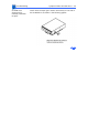
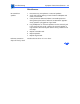
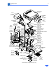
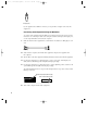
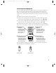
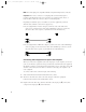
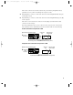
Table Of Contents
- Power Macintosh G3 Desktop
- Hot Issues
- Introduction
- Shared Logic Board
- Processor Module Vs. Card
- Power Supply Jumper
- Processor Module Jumper
- Warranty Sticker
- Power Supply Voltage Setting
- Voltage Regulator
- I/O Card
- ROM DIMM
- SDRAM DIMMs
- SGRAM Video Memory
- EIDE Bus Issue
- Master/Slave Support
- Ultra Wide SCSI Cable Routing
- DVD-ROM Disk Damage
- CD-ROM Ejection Problem
- HFS+ Formatted Drives
- Power-On Issue
- Basics
- Overview
- Data Buses
- Ultra Wide SCSI Card
- 10/100 BaseT Ethernet Card
- DVD-ROM Drive Technology
- FireWire Technology
- The Cuda Chip
- Resetting the Logic Board
- Sound
- Video Input and Output
- The DAV Connector
- Voltage Switch
- PowerPC G3 and Backside Cache
- SDRAM DIMMs
- SGRAM Video Memory
- DIMM Slots
- Peripheral Component Interconnect (PCI)
- Front View
- Rear View
- Internal Locator
- Logic Board
- Repair Strategy
- Warranty/AppleCare/ARIS
- G3 Design Information
- PowerPC Design Information
- Specifications
- Take Apart
- Top Housing
- Bezels
- Chassis Latch
- CD-ROM or DVD-ROM Drive
- Zip Drive
- Floppy Drive
- Drive Chassis
- Open/Remove Card Retainer Baffle
- Open Internal Chassis
- Hard Drive
- Drive Rails
- Power Supply
- Speaker
- Power Actuator
- Processor Module
- Battery
- PCI Cards
- Ultra Wide SCSI PCI Card
- FireWire PCI Card
- I/O Card
- Logic Board
- Rear Panel
- Bottom Chassis
- Modem Card
- Upgrades
- Troubleshooting
- Exploded View
- Screw Matrix
- Audio/Video Card Info
- Build-to-Order Info
- Hot Issues
If the S-video connector doesn’t slide easily into the port, check the pin alignment and try
again. Don’t use force, which could damage the computer or cable.
4 Plug the RCA-type connectors on the audio cables into the left and right RCA Audio Out ports
on the VCR or camera.
5 Plug the RCA-type connectors on the audio cables into the left and right RCA input ports (-)
on the computer.
If the cable is color-coded, the red connector is for the right port, and the black or white
connector is for the left port.
The next four illustrations show S-video connections and composite video connections for
both a VCR and a camera. Your finished connections should look like one of the following:
S-video connection for input from a VCR
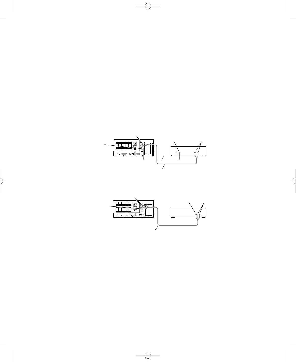
Composite video connection for input from a VCR
Composite
video
input port
Audio input ports (left and right)
Triple RCA-plug cable (available at most electronics supply stores)
VCR
˜
-
Video Out
port
Audio Out ports
(left and right)
S-video
input port
S-video Out
port
S-video
cable
VCR
æ
Audio input ports (left and right)
Audio Out ports
(left and right)
Dual RCA-plug cable (available at most electronics supply stores)
-
5
033-1009 AV Card Update 4/7/98 7:18 PM Page 5