K Service Source Macintosh IIcx/IIci/ Quadra 700 Macintosh IIcx Macintosh IIci Macintosh Quadra 700
K Service Source Basics Macintosh IIcx/IIci/Quadra 700
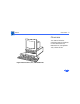
Basics Overview - 2 Overview This manual includes complete repair procedures for the Macintosh IIcx, Macintosh IIci, and Quadra 700, shown at left.
K Service Source SpeciÞcations Macintosh IIcx/IIci/Quadra 700
Specifications Processor - 1 Processor CPU Macintosh IIcx Motorola 68030 microprocessor 15.
Specifications Coprocessor Processor - 2 Built-in floating-point unit (FPU)
Specifications Memory - 3 Memory RAM Macintosh IIcx 1 MB, expandable to 128 MB (120 ns or faster SIMMs) Macintosh IIci 1 MB, expandable to 128 MB (80 ns or faster SIMMs) Quadra 700 4 MB, expandable to 8 MB (80 ns, I MB SIMMs) or 20 MB (third-party 4 MB SIMMs) ROM Macintosh IIcx 256K Macintosh IIci 512K
Specifications Quadra 700 Memory - 4 1 MB soldered on logic board; ROM SIMM socket available
Specifications Disk Storage - 5 Disk Storage Floppy Drive Internal 1.
Specifications I/O Interfaces - 6 I/O Interfaces Floppy Drive One DB-19 serial port for connecting external floppy drives SCSI One DB-25 external connector Apple Desktop Bus Two Apple Desktop Bus (ADB) ports Serial Two RS-232/RS-422 serial ports; mini DIN-8 connectors Expansion Macintosh IIcx/IIci Three NuBus slots Quadra 700 Two NuBus slots and one processor-direct slot
Specifications Sound I/O Interfaces - 7 Stereo sound jack Video Macintosh IIci/ Quadra 700 One DB-15 video port for built-in video Ethernet Quadra 700 Built-in Ethernet port; AUI-15 connector
Specifications I/O Devices - 8 I/O Devices Keyboard Apple Keyboard Mouse ADB mouse; DIN-4 connector
Specifications Sound and Video - 9 Sound and Video Sound Generator Apple sound chip provides 8-bit stereo sampling at 44.
Specifications Electrical - 10 Electrical Line Voltage 100Ð240 VAC, automatically configured Frequency 50Ð60 Hz, single phase Maximum Power Macintosh IIcx/IIci 90 W (not including monitor power) Quadra 700 130 W (not including monitor power) 90 W continuous
Specifications Physical - 11 Physical Dimensions Height: 5.5 in. (14.0 cm) Width: 11.9 in. (30.2 cm) Depth: 14.4 in. (36.5 cm) Weight 14 lb. (6.
K Service Source Troubleshooting Macintosh IIcx/IIci/Quadra 700
Troubleshooting General - 1 General The Symptom Charts included in this chapter will help you diagnose specific symptoms related to your product. Because cures are listed on the charts in the order of most likely solution, try the first cure first. Verify whether or not the product continues to exhibit the symptom. If the symptom persists, try the next cure. (Note: If you have replaced a module, reinstall the original module before you proceed to the next cure.
Troubleshooting Symptom Charts/System - 2 Symptom Charts System Does not power on— screen is black, fan is not running, and LED is not lit 1 2 3 4 5 Check cables. Plug monitor directly into wall socket, and verify that monitor has power. Replace power cord. Replace power supply. Replace logic board. Retain customer’s SIMMs. Clicking, chirping, or thumping 1 2 Replace power supply. Replace logic board. Retain customer’s SIMMs.
Troubleshooting Symptom Charts/System (Continued) - 3 System (Continued) System shuts down intermittently 1 4 5 Make sure air vents on sides and top of case are unobstructed. Thermal protection circuitry may shut down system. After 30–40 minutes, system should be OK. Replace power cord. Check batteries. Refer to “Battery Verification” in Additional Procedures. Replace power supply. Replace logic board. Retain customer’s SIMMs. 1 2 3 4 5 Make sure system software is correct version.
Troubleshooting Symptom Charts/Video - 4 Video Screen is dark, audio and drive operate, fan is running, and LED is lit 1 2 Adjust brightness on monitor. Replace monitor. Refer to appropriate monitor manual to troubleshoot defective monitor. 3 Replace video cable. 4 Move video card to different slot. 5 Replace video card. 6 Quadra 700: Replace VRAM SIMMs. 7 Macintosh IIcx/IIci: Make sure ROM jumper is on. 8 Replace SIMMs. 9 Replace logic board. Retain customer’s SIMMs. 10 Replace power supply.
Troubleshooting Symptom Charts/Video (Continued) - 5 Video (Continued) Screen is dark, audio and drive do not operate, but fan is running and LED is lit 1 2 3 4 5 6 7 8 9 Replace video cable. Replace monitor. Refer to appropriate monitor manual to troubleshoot defective monitor. Quadra 700: Replace VRAM SIMMs. Macintosh IIcx/IIci: Make sure ROM jumper is on. Remove NuBus cards. Remove peripherals. Replace SIMMs. Replace logic board. Retain customer’s SIMMs. Replace power supply.
Troubleshooting Symptom Charts/Video (Continued) - 6 Video (Continued) Partial or whole screen is bright and audio is present, but no video information is visible 1 Screen is completely dark, fan is not running, and LED is not lit 1 2 3 4 5 2 3 4 Replace monitor. Refer to appropriate monitor manual to troubleshoot defective monitor. Replace video cable. Move video card to different slot. Replace video card. Replace logic board. Retain customer’s SIMMs.
Troubleshooting Symptom Charts/Floppy Drive - 7 Floppy Drive Audio and video present, but internal drive does not operate 1 2 3 4 5 6 Replace disk with known-good system disk. Verify that all external SCSI devices are disconnected. Replace internal floppy drive cable. Replace internal floppy drive. Replace logic board. Retain customer’s SIMMs. Replace power supply. Disk ejects; display shows icon with blinking “X” 1 2 3 4 Replace disk with known-good system disk. Replace internal floppy drive cable.
Troubleshooting Symptom Charts/Floppy Drive (Continued) - 8 Floppy Drive (Continued) Will not eject disk Attempts to eject disk, but doesn’t 1 2 3 Switch off computer. Hold mouse button down while you switch computer on. Eject disk manually. Replace floppy drive. 1 2 3 Push disk completely in. Eject disk manually. Replace floppy drive.
Troubleshooting Symptom Charts/Hard Drive - 9 Hard Drive Internal hard drive runs continuously 1 2 3 Replace hard drive data cable. Replace internal hard drive. Replace logic board. Retain customer’s SIMMs. Internal hard drive does not operate 1 2 3 4 Replace hard drive data cable. Replace hard drive power cable. Replace hard drive. Replace logic board. Retain customer’s SIMMs.
Troubleshooting Symptom Charts/Peripherals - 10 Peripherals Cursor does not move 1 2 3 5 Reboot system. Check mouse connection. If mouse was connected to keyboard, connect mouse to a computer ADB port instead and disconnect the keyboard. If mouse works, replace the keyboard. If mouse does not work in any ADB port on computer, replace mouse. Replace logic board. Retain customer’s SIMMs. 1 2 Replace mouse. Replace logic board. Retain customer’s SIMMs.
Troubleshooting Symptom Charts/Peripherals (Continued) - 11 Peripherals (Continued) Double-click doesn’t open an application, disk, or server 1 2 3 4 5 Remove duplicate system files on the hard drive. Clear parameter RAM. System 7: Hold down
Troubleshooting Symptom Charts/Peripherals (Continued) - 12 Peripherals (Continued) No response to any key on the keyboard 1 2 3 4 Check keyboard connection to ADB port. Replace keyboard cable. Replace keyboard. Replace logic board. Retain customer’s SIMMs. Known-good ImageWriter or Imagewriter II does not print 1 2 3 4 Make sure System is 6.0.4 and Finder is 6.1 (or later). Make sure the Chooser and Control Panel settings are correct. Replace printer interface cable. Replace logic board.
Troubleshooting Symptom Charts/Miscellaneous - 13 Miscellaneous No sound from speaker 1 2 3 Verify that volume setting in the Control Panel is 1 or above. Replace speaker. Replace logic board. Retain customer’s SIMMs. Clock not running 1 Replace battery. See “Battery Verification” in Additional Procedures. Replace logic board. Retain customer’s SIMMs.
K Service Source Take Apart Macintosh IIcx/IIci/Quadra 700
Take Apart Cover - 1 Cover No preliminary steps are required before you begin this procedure. 1 2 Remove the Phillips screw. Pull up on the tabs and lift the cover until it comes off the front end.
Take Apart Speaker Bracket and Speaker - 2 Speaker Bracket and Speaker Speaker Bracket and Speaker Before you begin, remove the cover. Caution: Review the ESD precautions in Bulletins/ Safety. Note: The speaker and speaker bracket are two separate, replaceable units. To remove the speaker, you must first remove the speaker bracket.
Take Apart Speaker Bracket and Speaker - 3 1 2 Speaker Connector Disconnect the speaker connector from the logic board. Gently lift the release latch and pull back on the bracket until it comes free from the case.
Take Apart Speaker Bracket and Speaker - 4 3 Speaker Bracket Speaker Caution: Do not push on the heavy paper part of the speaker. Gently push the speaker from the bracket.
Take Apart Power Supply - 5 Power Supply Power Supply Before you begin, remove the cover. Caution: Review the ESD precautions in Bulletins/ Safety.
Take Apart Power Supply - 6 Power Supply Lip Note: Use some force in lifting the power supply. If the power supply does not move, verify that the latch is released. Power Supply Lip Release the latch and lift the power supply from the computer. SlotSupply Power in Case Slot in Case Latch Replacement Note: Make sure the lips of the power supply align with the slots in the case. Slide the power supply down until you hear a click.
Take Apart Fan Bracket and Fan - 7 Fan Bracket and Fan Before you begin, remove the following: • Cover • Power supply Caution: Review the ESD precautions in Bulletins/ Safety. Fan Bracket and Fan Note: The fan and fan bracket are two separate, replaceable units. To remove the fan, you must first remove the fan bracket.
Take Apart Fan Bracket and Fan - 8 1 2 Bracket Latches Fan Power Cable Connector Metal Tabs 3 Gently squeeze together the two bracket latches and release them from the metal tabs. Push up on the latches until you can access the fan power cable connector. Disconnect the cable from the power supply and pull the fan bracket from the case.
Take Apart Fan Bracket and Fan - 9 Bracket 4 Release the two latches and push the fan from the bracket. Replacement Note: Push the fan wire into the power supply case far enough to prevent the fan blades from striking the wire.
Take Apart Hard Drive - 10 Hard Drive Hard Drive Before you begin, remove the following: • Cover • Power supply Caution: Review the ESD precautions in Bulletins/ Safety.
Take Apart Hard Drive - 11 Note: The hard drive is located on the top of the drive mount. You can remove the hard drive with or without removing the mount. The following procedure describes how to remove the hard drive without removing the mount. (The procedure for removing the mount is in “Floppy Drive and Mount.
Take Apart Hard Drive - 12 1 Hard Drive Data Cable Hard Drive Power Cable Disconnect the hard drive data cable and hard drive power cable from the hard drive.
Take Apart Hard Drive - 13 2 LED LED Holder Lift the LED holder on the front of the case and pull out the LED.
Take Apart Hard Drive - 14 Hard Drive Tab 3 4 Tab Squeeze the two tabs and gently pull up. Remove the hard drive along with its carrier. Replacement Note: For information on removing the hard drive from the carrier and returning drives, cables, and carriers to Apple, refer to Additional Procedures in the Hard Drives manual.
Take Apart Floppy Drive and Mount - 15 Floppy Drive and Mount Before you begin, remove the following: • Cover • P ower supply Caution: Review the ESD precautions in Bulletins/ Safety. Note: To remove the floppy drive, you must remove the drive mount.
Take Apart Floppy Drive and Mount - 16 1 LED LED Holder Lift the LED holder on the front of the case and pull out the LED.
Take Apart Floppy Drive and Mount - 17 2 3 Hard Drive Data Cable Paper Tab Remove the screw from the drive mount. Pull up on the paper tab and disconnect the hard drive data cable from the logic board.
Take Apart Floppy Drive and Mount - 18 4 Hard Drive Power Cable Floppy Drive Cable Disconnect the floppy drive cable and hard drive power cable from the logic board.
Take Apart Floppy Drive and Mount - 19 5 6 Latch Release the latch and pull the mount toward the rear of the case about 1/2 inch. Lift the mount from the case.
Take Apart Floppy Drive and Mount - 20 Floppy Drive 7 8 Drive Latch Turn over the mount and gently push down the drive latch. Slide the floppy drive toward the front of the mount about 1 inch and pull the drive out of the mount.
Take Apart Floppy Drive and Mount - 21 Replacement Note: Apple recommends using dust shields on 1.4 MB SuperDrives. All 1.4 MB replacement drives ship with the dust shield already installed. If you plan to install a dust shield on the current drive, you must first clean the drive.
Take Apart Logic Board - 22 Logic Board Before you begin, remove the following: • Cover • Expansion cards • Power supply • Drive mount • Reset/interrupt switch • Speaker bracket Logic Board Caution: Review the ESD precautions in Bulletins/ Safety.
Take Apart Logic Board - 23 Logic Board 1 2 Slide the logic board toward the front of the case until the board stops. Gently lift the front end of the logic board and remove the board from the case. Replacement Note: Before you replace the logic board, make sure the metal grounding tabs that surround the port holes on the rear of the case are not folded in front of the holes.
Take Apart Logic Board - 24 Replacement Note: Remove the SIMMs from the defective logic board and install them on the replacement logic board.
K Service Source Upgrades Macintosh IIcx/IIci/Quadra 700
Upgrades Macintosh IIci Upgrade - 1 Power Cable Macintosh IIci Logic Board Macintosh IIci Upgrade SIMMs Bottom Case Before you begin,remove the following: • Cover • Expansion cards • Power supply • Drive mount • Reset/interrupt switch • Speaker bracket • Logic board Note: The Macintosh IIci Upgrade Kit for the Macintosh IIcx includes a IIci logic board, 1 MB of
Upgrades Macintosh IIci Upgrade - 2 80 ns fast page mode DRAM SIMMs, a new bottom case, and a new hard drive power cable. Caution: Review the ESD precautions in Bulletins/ Safety.
Upgrades Macintosh IIci Upgrade - 3 1 SIMM Removal Tool 2 SIMM Using the SIMM removal tool, remove the DRAM SIMMs from the old logic board and, if they are 120 ns SIMMS, give them to the customer. Discard the bottom case. (You need not return it to Apple.
Upgrades Macintosh IIci Upgrade - 4 3 Insert the new Macintosh IIci logic board into the new bottom case. Replacement Caution: Be sure to insert the replacement DRAM SIMMs (or other 80 ns SIMMs) into the Macintosh IIci logic board. If you use the 120 ns SIMMs from the Macintosh IIcx, the new Macintosh IIci will not function correctly.
Upgrades Macintosh IIci Upgrade - 5 the new hard drive power cable), power supply, and reset/interrupt switch. (Refer to Take Apart for detailed procedures.) If the unit contains a hard drive, install the hard drive light pipe from the old case in the new Macintosh IIci bottom case.
Upgrades Quadra 700 Upgrade - 6 Power Cable Quadra 700 Upgrade Before you begin, remove the following: • Cover • Expansion cards • Power supply • Drive mount • Reset/interrupt switch • Speaker bracket • Logic board Quadra 700 Logic Board Bottom Case Note: The Macintosh Quadra 700 Upgrade Kit includes a Quadra 700 logic board, a new bottom case, and a new hard drive power cable.
Upgrades Quadra 700 Upgrade - 7 Caution: Review the ESD precautions in Bulletins/ Safety.
Upgrades Quadra 700 Upgrade - 8 1 SIMM Removal Tool 2 SIMM Using the SIMM removal tool, remove the DRAM SIMMs from the old logic board and, if they are 120 ns SIMMS, give them to the customer. Discard the bottom case. (You need not return it to Apple.
Upgrades Quadra 700 Upgrade - 9 3 Insert the new Quadra 700 logic board into the new bottom case. Replacement Caution: Be sure to insert the replacement DRAM SIMMs (or other 80 ns SIMMs) into the Quadra 700 logic board. If you use 120 ns SIMMs, the new Quadra 700 will not function correctly.
Upgrades Quadra 700 Upgrade - 10 hard drive power cable), power supply, and reset/ interrupt switch. (Refer to Take Apart for detailed procedures.
Upgrades Expansion Cards - 11 Expansion Cards Before you begin,remove the cover. Caution: Review the ESD precautions in Bulletins/ Safety. Caution: Pull up evenly on both sides of the card to avoid bending the connector pins. Expansion Card Card Expansion Carefully grasp each end of the card and pull straight up to remove it.
Upgrades Expansion Cards - 12 Replacement Caution: When replacing the card, do not force it into the expansion slot. If the card does not seat properly, remove it and try again.
Upgrades Power Macintosh Upgrade Card - 13 Power Macintosh Upgrade Card By installing this card in the Macintosh Quadra 700 Processor-Direct Slot (PDS), you can upgrade the Quadra 700 to a PowerPC microprocessor. For more information, including installation instructions, refer to Basics in the Power Macintosh Upgrade Card manual.
K Service Source Additional Procedures Macintosh IIcx/IIci/Quadra 700
Additional Procedures Lithium Battery Battery Verification - 1 Battery Verification Before you begin, remove the following: • Cover • P ower supply • Drive mount Warning: Review battery handling and disposal instructions in Bulletins/ Safety. ± Caution: Review ESD precautions in Bulletins/ Safety.
Additional Procedures Battery Verification - 2 1 Negative Probe 2 Positive Probe 3 Set the voltmeter to the 10 volts DC scale. Hold the positive probe of the voltmeter to the positive end of the battery (marked “+” on the logic board) and the negative probe to the negative end of the battery. If the battery voltage is below 2.8 volts, replace the battery. Refer to “Battery Replacement” in this chapter.
Additional Procedures Lithium Battery Battery Replacement - 3 Battery Replacement Before you begin, remove the following: • Cover • P ower supply • Drive mount Warning: Review battery handling and disposal instructions in Bulletins/ Safety. ± Caution: Review ESD precautions in Bulletins/ Safety.
Additional Procedures Battery Replacement - 4 1 Using a small flat-blade screwdriver, pry open the latch at the end of the holder and lift off the cover.
Additional Procedures Battery Replacement - 5 2 3 Grasp the battery and remove it from the holder. Return the battery to Apple for proper disposal. For battery packaging and labeling instructions, refer to the safety information in Bulletins/Safety.
Additional Procedures Reset/Interrupt Switch - 6 Reset/Interrupt Switch Reset/Interrupt Switch Before you begin, remove the cover. Caution: Review ESD precautions in Bulletins/ Safety.
Additional Procedures Reset/Interrupt Switch - 7 1 Reset/Interrupt Switch 2 With one finger, lift the center tab of the switch. Gently lift the rear of the switch up and away from the front of the case.
Additional Procedures SCSI Termination - 8 SCSI Termination Block SCSI Connector Logic Board SCSI Termination No preliminary steps are required before you begin this procedure. The SCSI termination block provides proper termination for systems without an internal hard drive. All Macintosh Quadra 700 computers that shipped without internal hard drives have the termination block attached to the logic board SCSI connector. After you install an internal hard drive, remove the block.
K Service Source Exploded View Macintosh IIcx/IIci/Quadra 700
Exploded View 1 Exploded View Macintosh IIcx/IIci and Quadra 700 416-1414 Top Cover Hard Drive Power Cable Hard Drive LED Cable Fan Bracket HDA Light Pipe 416-1412 Fan Drive Carrier 444-6104 Internal Shield Power Supply 844-0081 Floppy Drive On/Off Button Speaker Bracket Speaker Reset/ Interrupt Switch Logic Board Bottom Case Power-On Light Pipe Feet AC Power Cable