K Service Source Macintosh Quadra 610/ Centris 610/WS 60 Macintosh Quadra 610 DOS Compatible Macintosh Quadra 610 Macintosh Centris 610 Workgroup Server 60
K Service Source Basics Macintosh Quadra 610/Centris 610/WS 60
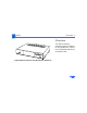
Basics Overview - 2 Overview This manual includes complete repair procedures for the Quadra 610, Centris 610, and WorkGroup Server 60 shown at left.
K Service Source Specifications Macintosh Quadra 610/Centris 610/WS 60
Specifications Processors - 1 Processors Centris 610/AWS 60 Motorola 68LC040 20 MHz Built-in memory management unit (MMU) Note: Apple does not provide a floating point unit (FPU) upgrade for this product. Quadra 610/AWS 60 Quadra 610: Optional Motorola 68LC040 or 68040 AWS 60: Motorola 68040 25 MHz Built-in memory management unit (MMU) Note: A floating point unit (FPU) coprocessor is included with the 68040 processor.
Specifications Quadra 610, DOS Compatible DOS Compatible Card Processors - 2 Motorola 68LC040 25 MHz Built-in memory management unit DOS compatible card 486SX microprocessor 25 MHz 32-bit addressing 32-bit data paths One 72-pin SIMM slot supports up to 64 MB expansion, 80 ns or faster SIMM. 512K, 80 ns video DRAM soldered on board supports standard VGA, many SVGA, and Macintosh monitors.
Specifications Memory - 3 Memory Centris 610/ Quadra 610 RAM ROM 4 or 8 MB RAM standard, expandable to 68 MB (80 ns or faster 72-pin SIMM) 1 MB AWS 60 RAM ROM 8 MB RAM standard, expandable to 68 MB (80 ns or faster 72pin SIMM) 1 MB
Specifications Memory - 4 PRAM 1 MB VRAM 256 bytes of nonvolatile parameter memory Clock/Calendar 512K, expandable to 1 MB (80 ns or faster 68-pin SIMM) CMOS custom chip with long-life lithium battery
Specifications Disk Storage - 5 Disk Storage Floppy Drive 1.4 MB Apple SuperDrive Hard Drive Centris 610/Quadra 610: 80 MB to 500 MB hard drive CD-ROM AWS 60: 230 MB or 500 MB hard drive Optional internal 5.25-in.
Specifications I/O Interfaces - 6 I/O Interfaces SCSI Apple Desktop Bus Serial One SCSI port; DB-25 connector Supports a maximum of six external devices (internal SCSI devices include the computer, which is always device 7) Two Apple Desktop Bus (ADB) ports; mini DIN-4 connectors Low-speed synchronous serial interface Two RS-232/RS-422 serial ports; mini DIN-8 connectors 230.4 Kbps maximum 0.
Specifications Sound Video Ethernet I/O Interfaces - 7 One stereo-capable output port One monaural input port One video port; DB-15 connector Supports Apple monitors (8-bit) VGA and SVGA monitors require a special adapter cable Centris 610: Optional on-board Ethernet port AWS 60/Quadra 610: On-board Ethernet
Specifications I/O Devices - 8 I/O Devices Keyboard Mouse Microphone Standard, extended, or adjustable keyboard connected through either of two ADB ports Maximum power draw for all ADB devices: 500 mA Keyboard draws 25–80 mA ADB Mouse II; mechanical tracking optical shaft or contact encoding (low power) Draws up to 80 mA Optional electret, omnidirectional microphone Microphone output voltage is 4 mV peak to peak at normal value Mini phone plug connector
Specifications Sound and Video - 9 Sound and Video Video Display Supports Apple monitors, including • Macintosh 12-in. Monochrome Display • Macintosh 12-in. RGB Display • AppleColor High-Res RGB 14-in. Monitor • Macintosh Color Display • Macintosh 15-in. Portrait Display • Macintosh 16-in. Color Display • Apple Two-Page 21-in. Monochrome Monitor • Macintosh 21-in.
Specifications Sound Sound and Video - 10 Custom sound chip supports stereo playback from compact discs and computer-generated stereo sounds through stereo output port Monaural sound input port
Specifications Electrical - 11 Electrical Line Voltage 100–240 VAC Line Frequency Power 50–60 Hz 112 W (not including monitor)
Specifications Physical - 12 Physical Dimensions Weight Height: 3.4 in. (85 mm) Width: 16.3 in. (415 mm) Depth: 4.2 in. (107 mm) 14.0 lb. (6.
Specifications Environmental - 13 Environmental Operating Temperature Storage Temperature 10–40°C (50–104°F) –40 to 47°C (–40 to 116.6°F) Relative Humidity 10–90% (noncondensing) Altitude 0–10,000 ft.
K Service Source Troubleshooting Macintosh Quadra 610/Centris 610/WS 60
Troubleshooting General/ - 1 General The Symptom Charts included in this chapter will help you diagnose specific symptoms related to your product. Because cures are listed on the charts in the order of most likely solution, try the first cure first. Verify whether or not the product continues to exhibit the symptom. If the symptom persists, try the next cure. (Note: If you have replaced a module, reinstall the original module before you proceed to the next cure.
Troubleshooting Symptom Charts/Video - 2 Symptom Charts Video Screen is dark, audio and at least one drive operate, fan is running, and LED is lit 1 2 3 4 5 6 7 Reset PRAM. Adjust brightness on monitor. Check cables. Replace monitor. Refer to appropriate monitor manual to troubleshoot defective monitor. Replace video cable. Replace VRAM SIMMs. Replace logic board. Retain customer’s SIMMs.
Troubleshooting Symptom Charts/Video (Continued) - 3 Video (Continued) Partial or whole screen is bright and audio is present, but no video information is visible 1 2 3 4 5 6 Reset PRAM. Check cables. Replace monitor. Refer to appropriate monitor manual to troubleshoot defective monitor. Replace video cable. Replace VRAM SIMMs. Replace logic board. Retain customer’s SIMMs.
Troubleshooting Symptom Charts/Video (Continued) - 4 Video (Continued) Screen is dark, audio and drive do not operate, fan is running, and LED is lit 1 2 3 4 5 Remove peripherals and third-party cards. Replace VRAM SIMMs. Replace DRAM SIMMs. Replace power supply. Replace logic board.
Troubleshooting Symptom Charts/Floppy Drive - 5 Floppy Drive Audio and video are present, but internal floppy drive does not operate 1 2 3 Replace internal floppy drive cable. Replace internal floppy drive. Replace logic board. Retain customer’s SIMMs. Floppy disk ejects, and display shows Mac icon with blinking “X” 1 2 3 4 Replace floppy disk. Replace floppy drive cable. Replace internal floppy drive. Replace logic board. Retain customer’s SIMMs.
Troubleshooting Symptom Charts/Floppy Drive (Continued) - 6 Floppy Drive (Continued) Floppy drive attempts to eject disk but doesn’t 1 2 3 Push floppy disk completely in. Eject floppy disk manually. Replace floppy drive.
Troubleshooting Symptom Charts/Hard Drive - 7 Hard Drive Internal hard drive runs continuously 1 2 3 Replace SCSI data cable. Replace internal hard drive. Replace logic board. Retain customer’s SIMMs. Internal hard drive does not operate 1 2 3 4 5 Replace SCSI data cable. Replace SCSI power cable. Check power to the hard drive. Replace hard drive. Replace logic board. Retain customer’s SIMMs.
Troubleshooting Symptom Charts/CD-ROM Drive - 8 CD-ROM Drive CD-ROM drive does not accept a compact disc 1 2 3 Exchange disc (if disc is dirty or damaged). Replace 50-pin ribbon cable. Replace CD-ROM drive mechanism. Macintosh does not display CD-ROM drive icon 1 2 3 4 5 Verify that CD-ROM extension is in System Folder. Verify the disc is in the drive correctly. Replace CD-ROM drive mechanism. Replace power supply. Replace SCSI data cable.
Troubleshooting Symptom Charts/Peripheral - 9 Peripheral Works with internal or external SCSI device, but does not work with both 1 Cursor does not move 1 2 3 4 2 3 4 5 6 Verify that SCSI select switch on any external device is set differently from any internal SCSI device setting. Verify that hard drive is terminated but optional CD-ROM is not terminated. Replace terminator on external hard drive. Replace SCSI select cable on external SCSI device. Reboot computer.
Troubleshooting Symptom Charts/Peripheral (Continued) - 10 Peripheral (Continued) Cursor moves, but clicking the mouse button has no effect 1 2 Replace mouse. Replace logic board. Retain customer’s SIMMs. Double-click does not open application, disk, or server 1 2 Remove duplicate system files from hard drive. Clear parameter RAM. Hold down
Troubleshooting Symptom Charts/Peripheral (Continued) - 11 Peripheral (Continued) No response to any key on the keyboard 1 2 3 4 Verify that keyboard is connected to ADB port. Replace keyboard cable. Replace keyboard. Replace logic board. Retain customer’s SIMMs.
K Service Source Take Apart Macintosh Quadra 610/Centris 610/WS 60
Take Apart Top Cover - 1 Top Cover Tabs Top Cover No preliminary steps are required before you begin this procedure. 1 2 Press up on the tabs at the back of the top cover. Tilt the back of the top cover and remove the top cover.
Take Apart Power Supply - 2 Power Supply Power Supply Before you begin, remove the top cover. Caution: Review the ESD precautions in Bulletins/ Safety.
Take Apart Power Supply - 3 1 Power Supply Remove the screw that secures the power supply.
Take Apart Power Supply - 4 2 Tab For easier access to the power supply, release the tabs of the floppy drive and slide the floppy drive forward a few inches. Note: If a CD-ROM drive is present, remove the SCSI data cable and move the CD-ROM drive forward. Refer to the “CD-ROM Drive” topic.
Take Apart Main Power Cable Power Supply - 5 3 CD-ROM Drive Power Cable Hard Drive Power Cable Disconnect these power supply cables: • Main power cable • Hard drive power cable • CD-ROM drive power cable (if installed)
Take Apart Power Supply - 6 4 Power Supply Slide the power supply forward slightly.
Take Apart Power Supply - 7 5 Power Switch Tilt the front of the power supply and lift it out of the computer. Replacement Note: Move the floppy drive forward. Press the actuator toward the back of the computer to properly seat the power switch in the actuator.
Take Apart Logic Board - 8 Logic Board Logic Board Before you begin, remove the following: • Top cover • Power supply Caution: Review the ESD precautions in Bulletins/ Safety.
Take Apart Logic Board - 9 Note: The logic board is secured with two screws. Standoff with Internal Screw 1 2 3 Using a long Phillips screwdriver, remove the screw from the center of the standoff. Remove the standoff. Remove the Phillips screw from the front edge of the logic board.
Take Apart Floppy Drive Cable Logic Board - 10 4 Speaker Cable 5 LED Cable CD-ROM Audio Cable SCSI Data Cable 6 Disconnect these cables from the logic board: • SCSI data cable • Speaker cable • LED cable • CD-ROM audio cable (if present) • Floppy drive cable Note: Lift the front edge of the logic board to make removing the floppy drive easier. Slide forward the hard drive and CD-ROM drive (if installed).
Take Apart Logic Board - 11 7 Slide the logic board toward the front of the computer.
Take Apart Logic Board - 12 8 Logic Board Remove the logic board. Replacement Note: Slide the hard drive and optional CD-ROM drive forward. Connect the floppy drive cable before replacing the logic board.
Take Apart Floppy Drive - 13 Floppy Drive Floppy Drive Before you begin, remove the top cover. Caution: Review the ESD precautions in Bulletins/ Safety.
Take Apart Floppy Drive - 14 1 Floppy Drive 2 Tab 3 Tab Tab Press the tabs outward and slide the floppy drive forward a few inches. Disconnect the floppy drive cable. Note: You can easily reach the floppy drive cable connector when the floppy drive is forward. Slide out the floppy drive.
Take Apart Hard Drive - 15 Hard Drive Hard Drive Before you begin remove the top cover. Caution: Review the ESD precautions in Bulletins/ Safety.
Take Apart SCSI Data Cable Hard Drive Power Cable Hard Drive - 16 1 Disconnect the SCSI data and hard drive power cables from the hard drive.
Take Apart Hard Drive - 17 2 Hard Drive EMI Shield Remove the hard drive EMI shield.
Take Apart Hard Drive - 18 3 Tab Press down on the tab and slide out the hard drive.
Take Apart CD-ROM Drive - 19 CD-ROM Drive CD-ROM Drive Before you begin, remove the top cover. Caution: Review the ESD precautions in Bulletins/ Safety.
Take Apart CD-ROM Drive - 20 1 CDROM Audio Cable 2 SCSI Data Cable Disconnect the SCSI data cable and CD-ROM drive power cable from the CD-ROM drive. Disconnect the CD-ROM audio cable.
Take Apart CD-ROM Drive - 21 3 CD-ROM EMI Shield Remove the CD-ROM drive EMI shield.
Take Apart CD-ROM Drive - 22 4 Press up on the tab and slide out the CD-ROM drive. Replacement Note: Be sure to remove the CD-ROM drive from the carrier prior to returning the drive to Apple.
Take Apart Internal Chassis - 23 Internal Chassis Internal Chassis Before you begin, remove the following: • Top cover • Power supply • Floppy drive • Hard drive • CD-ROM drive (if installed) • Logic board Caution: Review the ESD precautions in Bulletins/ Safety.
Take Apart Internal Chassis - 24 Internal Chassis Support Post Rail and Metal Tab Tab Note: The chassis is secured to the bottom cover by two tabs at the front of the unit, two rail and tab sets at the sides of the unit, support posts at the back of the chassis, and hidden brackets that slide into the bottom cover. 1 2 Press up on one of the front tabs while lifting the support post. Repeat this step on the other side until the internal chassis slides easily toward the back of the computer.
Take Apart Internal Chassis - 25 3 Internal Chassis 4 Press down and slide the chassis toward the back of the computer. Remove the chassis. Note: The LED cable, floppy drive cable and speaker are not part of the internal chassis assembly.
Take Apart Internal Chassis - 26 Speaker and Cable LED Cable Floppy Drive Cable 5 Turn the chassis over. 7 Remove the speaker cable from its routing guides. 6 Remove the floppy drive cable and the LED cable.
Take Apart Torx Screws Internal Chassis - 27 8 9 Remove the two torx screws from the speaker. Lift out the speaker.
Take Apart Bottom Cover Internal Chassis Metal Tab Rail Internal Chassis - 28 Replacement Note: To replace the chassis, carefully slide the rails at the side of the chassis under the metal tabs.
Take Apart Internal Chassis - 29 Replacement Note: After carefully aligning the side rails, push down firmly on the chassis and slide it toward the front of the unit. The tabs will snap in place.
Take Apart Bottom Cover - 30 Bottom Cover Bottom Cover Before you begin, remove the following: • Top cover • Power supply • Floppy drive • Hard drive • CD-ROM drive (if installed) • Logic board • Internal chassis Caution: Review the ESD precautions in Bulletins/ Safety
Take Apart Bottom Cover - 31 1 2 Actuator 3 Tab Tab Shift the actuator toward the back of the unit. Squeeze together the tabs on the shaft of the actuator. Remove the actuator.
Take Apart Bottom Cover - 32 4 Insulator Shield Lift out the insulator shield. Replacement Note: There is only one correct position for the insulator shield. Match the notches on the sides of the insulator sheet with the corresponding metal stops.
Take Apart Bottom Cover - 33 5 Tab Tab 6 I/O Panel Using a screwdriver, release the tabs on the upper-rear edge of the bottom cover. Push out the I/O panel.
K Service Source Upgrades Macintosh Quadra 610/Centris 610/WS 60
Upgrades Expansion Cards - 1 Expansion Card Slot Expansion Cards Before you begin, remove the cover. Caution: Review the ESD precautions in Bulletins/ Safety.
Upgrades Expansion Cards - 2 Expansion Port Cover 1 Remove the expansion port cover from the back panel.
Upgrades Expansion Card Expansion Cards - 3 2 3 Loosely connect the expansion card connector to the adapter card connector. Note: Be sure to fit the adapter card pin into the expansion card hole. Gently press the connectors together.
Upgrades Expansion Cards - 4 4 Adapter Card Tab Adapter Card Connector Bottom Case Slot Expansion Slot Insert the connector on the bottom of the adapter card into the expansion slot. Note: Make sure that the tab on the side of the adapter card slides into the slot on the side of the bottom case.
Upgrades Expansion Cards - 5 5 Thumbscrews Attach the thumbscrews.
Upgrades CD-ROM Drive Upgrade - 6 CD-ROM Drive Bay CD-ROM Drive Upgrade Before you begin, remove the top cover. Caution: Review the ESD precautions in Bulletins/ Safety.
Upgrades CD-ROM Drive Upgrade - 7 1 2 Slotted CD-ROM Drive Bezel Remove the blank CD-ROM drive bezel from the top cover. Install the slotted CD-ROM drive bezel in the top cover.
Upgrades CD-ROM Drive Upgrade - 8 3 5.25'' Drive Bay Shield Pry off the metal 5.25" drive bay shield.
Upgrades CD-ROM Drive Upgrade - 9 CD-ROM Drive Carrier CD-ROM Drive 4 Attach the CD-ROM drive carrier to the CD-ROM drive with four Phillips screws.
Upgrades CD-ROM Drive Upgrade - 10 CD-ROM Drive CD-ROM Drive Carrier 5 Push in the CD-ROM drive and carrier.
Upgrades CD-ROM Drive Upgrade - 11 6 Bottom Cover 7 Align the slots at the lower edge of the CD-ROM shield with the tabs on the bottom cover. Swing up the CD-ROM shield until it snaps securely onto the bottom cover.
Upgrades CD-ROM Audio Cable CD-ROM Drive Upgrade - 12 SCSI Data Cable 8 CD-ROM Drive Power Cable 9 CD-ROM Audio Cable Connect these cables from the power supply to the CD-ROM drive: • SCSI data cable • CD-ROM drive power cable Connect one end of the audio cable to the CDROM drive and the other end of the audio cable to the logic board.
Upgrades 660AV Upgrade - 13 Centris 660AV Logic Board 660AV Upgrade Before you begin, remove the following: • Top cover • P ower supply • Logic board Caution: To prevent ESD damage to components, wear a grounding wriststrap. Review the ESD precautions in Bulletins/Safety.
Upgrades 660AV Upgrade - 14 Note: The Centris 610AV Upgrade Kit for the Centris 610 includes a Centris 610AV Logic Board, product labels, and 1/O panel.
Upgrades 660AV Upgrade - 15 Note: The Centris 610 logic board is secured with two screws. Standoff with Internal Screw 1 2 3 Using a long Phillips screwdriver, remove the screw from the center of the standoff. Remove the standoff. Remove the Phillips screw from the front edge of the Centris 610 logic board.
Upgrades Floppy Drive Cable 660AV Upgrade - 16 4 Speaker Cable LED Cable CD-ROM Audio Cable SCSI Data Cable 5 Disconnect these cables from the Centris 610 logic board: • SCSI data cable • Speaker cable • LED cable • CD-ROM audio cable (if present) • Floppy drive cable Note: Lift the front edge of the logic board to make removing the floppy drive easier. Slide forward the hard drive and CD-ROM drive (if installed).
Upgrades 660AV Upgrade - 17 6 7 Slide the Centris 610 logic board toward the front of the computer. Remove the Centris 610 logic board.
Upgrades 660AV Upgrade - 18 8 Tab Tab Centris 610 I/O Panel 9 Using a screwdriver, release the tabs on the upper-rear edge of the bottom cover. Push out the Centris 610 I/O panel.
Upgrades 660AV Upgrade - 19 10 Position the Centris 660AV I/O panel in the bottom cover. Centris 660AV I/O Panel Tabs Tabs 11 Press the I/O panel to snap the tabs in place.
Upgrades 660AV Upgrade - 20 12 Place the Centris 660AV logic board in the bottom cover just forward of the I/O panel and slide the logic board into place.
Upgrades 660AV Upgrade - 21 SCSI Data Cable Video-Out Cable Video-In Cable 13 Connect these cables to the back edge of the logic board: • Video-out cable • Video-in cable • SCSI data cable
Upgrades 660AV Upgrade - 22 LED Cable Floppy Drive Cable Speaker Cable 14 Connect these cables to the front edge of the Centris 660AV logic board: • Floppy drive cable • Speaker cable • LED cable • CD-ROM audio cable (if present)
Upgrades Standoff with Internal Screw Phillips Screw 660AV Upgrade - 23 Replacement Note: Replace the standoff with the internal Phillips screw. Replace the Phillips screw on the front edge of the logic board.
Upgrades Power Macintosh Card - 24 Power Macintosh Card Before you begin, remove the cover. Caution: Review the ESD precautions in Bulletins/ Safety. Installing this card in the computer’s ProcessorDirect Slot (PDS) upgrades this 68040-based computer to a PowerPC-based computer.
Upgrades Power Macintosh Card - 25 Refer to “Expansion Cards” in this chapter for installation procedures. Refer to Power Macintosh Card manual for more information.
Upgrades Power Mac Upgrade - 26 Power Mac Upgrade No preliminary steps are required before you begin this procedure. The Centris 610 and Quadra 610 can be upgraded to a Power Macintosh 6100/60 or Power Macintosh 6100/ 60AV. The AWS 60 can be upgraded to a Workgroup Server 6150.
Upgrades Power Mac Upgrade - 27 For upgrade instructions, refer to the Upgrades chapter in the Power Macintosh 6100/WS 6150 manual.
K Service Source Additional Procedures Macintosh Quadra 610/Centris 610/WS 60
Additional Procedures Battery Verification - 1 Battery Verification Battery Before you begin, remove the cover. If handled or discarded improperly, the lithium battery in the computer could explode. Review battery-handling and disposal instructions in Bulletins/Safety. ±Warning: Caution: Review the ESD precautions in Bulletins/ Safety.
Additional Procedures Battery Verification - 2 1 2 Negative Probe Positive Probe 3 Set the voltmeter to the 10 volts DC scale. Hold the positive probe of the voltmeter to the positive end of the battery (marked “+” on the logic board) and the negative probe to the negative end of the battery. If the battery voltage is below 3.2 volts, replace the battery. Refer to “Battery Replacement” in this chapter.
Additional Procedures Battery Replacement - 3 Battery Replacement Battery Before you begin, remove the cover. If handled or discarded improperly, the lithium battery in the computer could explode. Review battery-handling and disposal instructions in Bulletins/Safety. ±Warning: Caution: Review the ESD precautions in Bulletins/ Safety.
Additional Procedures Battery Replacement - 4 1 Using a small flat-blade screwdriver, pry open the latch at the end of the battery holder and lift off the cover.
Additional Procedures Battery Replacement - 5 2 3 Grasp the battery and remove it from the holder. Return the battery to Apple for proper disposal. For battery packaging and labeling instructions, refer to the safety information in Bulletins/Safety.
Additional Procedures CPU Replacement - 6 Processor Chip CPU Replacement Before you begin, remove the following: • Top cover • Power supply • Expansion card • Logic board Caution: Review the ESD precautions in Bulletins/ Safety.
Additional Procedures Processor Chip CPU Replacement - 7 1 2 PGA Processor Chip Removal Tool 3 Position the teeth of the PGA processor chip removal tool in the groove between the chip and the socket. Caution: Be sure to lift up on the handle of the chip removal tool. Pressing down could damage components on the board. Gently lift up the handle to loosen each side of the processor chip from the socket. Remove the processor chip.
Additional Procedures CPU Replacement - 8 4 Processor Chip Marked Corner Marked Corner Processor Socket 5 Position the marked corner of the processor chip over the marked corner of the processor socket. Replacement Caution: Forcing the processor into the socket could damage processor pins. If the processor resists installation, check pin alignment. Carefully align the pins of the processor chip with the corresponding holes in the socket.
Additional Procedures CPU Replacement - 9 6 Press down firmly on each edge of the processor chip.
K Service Source Exploded View Macintosh Quadra 610/Centris 610/WS 60
Exploded View 1 Exploded View Top Cover 922-0545 (for Manual Insert Floppy) 922-0368 Blank Bezel 922-0358 SCSI Cable 922-0804 Support Column 922-0356 Slotted CD Bezel with Caddy 922-0355 Slotted CD Bezel Caddiless Power Supply 661-1688 Logic Board 661-0042 (No FPU) 661-0043 (FPU) 661-1681 661-1682 (with E-Net) Internal Chassis 922-0359 Floppy Drive Cable 922-0351 Speaker 922-0353 LED Cable 922-0354 On/Off Actuator 922-0357 Insulator Sheet (plastic) 922-0361 AV Adapter Cables CD Audio Cable 922-0842