Xserve (Late 2006/Early 2008) Logic Board Replacement Instructions Follow the instructions in this document carefully. Failure to follow these instructions could damage your equipment and void its warranty. Online instructions are available at http://www.apple.com/support/diy/. Working Safely Inside the Xserve Always touch the Xserve enclosure to discharge static electricity before you touch any components inside the Xserve.
Removing the Xserve from a Rack 1. Alert users that the server will be unavailable for a period of time. 2. Shut down the Xserve (see the Xserve User’s Guide for help) and then wait to let the Xserve internal components cool. Warning: Always shut down the Xserve before opening it to avoid damaging its internal components or the components you want to install or remove. Don’t open the Xserve or try to install or remove items inside while it is turned on.
Opening the Xserve Loosen the thumbscrews at the back of the top cover and slide the cover back and up to remove it. If you have difficulty removing the cover, check the enclosure lock on the front panel. Warning: Even after you shut down the Xserve, its internal components can be very hot. Let it cool before you open it. Important: To minimize the possibility of damage to Xserve components due to static discharge, wear an antistatic wrist strap, if possible, while you work inside the Xserve.
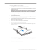
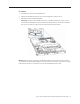
Power Supplies 1. Pull the handle to release the first power supply and slide it out of the bay. Pull the handle to unlatch the power supply and remove it. 2. Repeat for the second power supply, if installed. PCI Riser Cards and Expansion Cards 1. Loosen the two captive screws that secure the riser bracket in slot 1 to the back panel. 2. Carefully pull up on the bracket and riser, with the expansion card still attached, to disconnect the riser from the logic board. Captive screws 3.
FB-DIMMs 1. Push down the ejectors on the FB-DIMM slot. 2. Holding the FB-DIMM by both top corners, lift it straight up out of the Xserve. 3. Repeat for the other installed FB-DIMMs. Important: The order of the FB-DIMMs in the slots can affect performance. Unless you are sure that all the FB-DIMMs are identical, keep track of which slot you remove each FB-DIMM from so you can return it to the same slot on the replacement logic board.
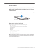
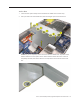
Airflow Duct 1. Loosen the five captive Phillips screws that fasten the airflow duct to the fan array. 2. Pull up on either side of the airflow duct, and lift it straight up and out of the Xserve. Caution: Try not to completely remove the screws from the airflow duct. Tiny black rubber washers hold these screws captive on the underside of the airflow duct. If the screws are completely removed, these rubber washers can easily fall into the enclosure and become lost.
Fan Array 1. Loosen the two captive thumbscrews that secure the fan array to the enclosure. 2. Lift the fan array to remove it from the Xserve. Note: You may need to move the front panel cable slightly out of the way of the fan array power connector during removal or replacement. Be careful not to pinch the front panel board cable between the fan array and any other surface inside. Note: You may encounter some resistance around the fan array power connector during removal.
Backplane-to-Logic Board I/O Cable 1. Disconnect the backplane-to-logic board cable from the logic board. 2. Disconnect the backplane-to-logic board cable from the drive interconnect backplane and remove the cable from the Xserve.
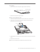
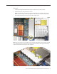
Processor Heat Sinks Note: Server configurations with a single processor have a regular heat sink and a blank heat sink installed. The blank heat sink is silver colored (as shown below) and should not be removed except when replacing a logic board. 1. Loosen the four screws securing the heat sink in the order indicated below. If two coppercolored heat sinks are installed, you must remove both heat sinks.
Caution: Whenever you handle a heat sink, handle it from the slotted sides, not the smooth sides. Grasping the smooth sides of the heat sink can compress its ribs causing permanent damage.
2. Caution: Each heat sink is connected to the logic board by a small 2-pin thermal sensor cable. Lifting the heat sink too quickly can damage the cable or connector. Because of the tight thermal bond between the processor and heat sink, be especially cautious to initially lift the heat sink no more than one centimeter (1 cm) off the processor. Do not pull on the cable as you lift each heat sink enough to disconnect the cable from the logic board.
Processor 1. Release the latch on the metal processor holder. 2. Rotate the top of the holder to the open position. 3. Carefully lift the processor out of the holder. Important: When removing or installing a processor, always hold the processor by three corners. Be extremely careful not to touch the gold pins on the bottom of the processor, as this type of connector is very sensitive to contamination. Also be careful not to touch the gold pins in the processor socket on the logic board.
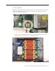
Video Mezzanine Card (if installed) 1. Remove the four 8-5-mm long Phillips screws that secure the mezzanine card to the logic board. 2. Pull up evenly on all sides of the card to disconnect it from its logic board connector under the card, and remove the card from the Xserve.
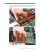
Logic Board 1. Study the next four images for properly moving the logic board before continuing with the steps. Caution: When removing and installing the logic board, be careful not to flex the logic board, which could damage the board or its components. To best distribute the weight of the logic board and minimize flexing, grasp the logic board only at the side and the end of the expansion card riser, as shown.
Caution: When transferring the logic board, be careful not to flex the logic board, which could damage the board or its components. To best distribute the weight of the logic board and minimize flexing, hold the logic board at the long sides near the center, as shown.
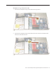
2. Disconnect the optical drive cable from the logic board. 3. Release the two locking levers on the front panel board cable connector and disconnect the cable from the logic board. Move the cable aside so you have access to the logic board. 4. Loosen the single thumbscrew on the power distribution board and slide the board away from and out of the connector on the logic board.
5. Following the order shown, loosen the nine thumbscrews that secure the logic board to the enclosure. Note: The thumbscrews are captive; you cannot remove them. 6. Grasping the logic board only by its expansion card riser and edge as shown, move it forward and up slightly to release it from the rear port openings in the enclosure. 7. Remove it from the Xserve.
Xserve (Early 2008): Packing the Used Logic Board Important: This packing procedure applies only to Xserve (Early 2008) logic boards. When packing the logic board, place the board in an antistatic bag and set it component-side up in the return box so that the raised areas on the board fit correctly between the foam supports on the box. Don’t bend or flex the logic board. 1. Holding the board at the long sides, place it in the antistatic bag. 2.
3. Place the logic board in the box, making sure it is component-side up and positioned with the Northbridge heat sink at the back of the box. 4. Follow any additional return instructions for your region, and close the box. Important: Make sure the foam supports align correctly with the raised areas on the board. When aligned correctly, the box closes easily.
Installing the Replacement Logic Board Important: When replacing the logic board, make sure the board’s rear port connectors fit through the appropriate openings in the Xserve’s back panel. Take special care to fit the clear plastic system identifier button through its opening. Don’t bend or flex the logic board. 1.
3. Following the order shown, use a screwdriver to tighten, but not overtighten, the nine thumbscrews that secure the logic board to the enclosure. 4. Slide the power distribution board back into place and tighten the thumbscrew. Note: Make sure the edge connector on the power distribution board goes completely into the connector on the logic board. If the power distribution board doesn’t slide easily, make sure the thumbscrew is popped up so it doesn’t catch on the mounting post beneath the board. 5.
Replacing the Processors 1. Unsnap the protective plastic cover from the first processor holder on the replacement logic board, unclip the holder latch, and open the holder. Plastic protective cover Processor holder 2. Holder latch Using a syringe of thermal grease, apply the entire contents of the syringe (approximately 4.5 cc) to the top surface of the processor. Important: Be sure not to get grease anywhere on the processor other than the very top, flat surface that directly contacts the heat sink.
3. Use the edge of the package that the alcohol wipe came in as a spatula to spread the thermal grease evenly over the entire top surface of the processor. Scrape off any excess grease with the package edge, then discard the package. 4. Holding the processor by three corners only, keep the processor level as you place it into its holder on the logic board, being careful not to get any thermal grease on the contacts of either the processor or its socket holder.
Note: When installing the processor on the logic board, align the processor notch with the tab on the processor holder, as shown. Then lower the processor straight down onto the socket.
5. Rotate the top of the holder to the closed position. 6. Engage the latch on the processor holder. Repeat the steps above for the second processor. Replacing the Processor Heat Sinks 1. Holding the heat sink by the slotted sides in one hand, reconnect the 2-pin thermal sensor cable for the heat sink to the logic board. Note: Make sure the connector on the sensor cable is oriented as shown, with the gold fingers facing up. 2.
Replacing the Backplane-to-Logic Board I/O Cable 1. Fold the cable to a 90-degree angle along its creases. 2. Connect the cable to the logic board first. Then press the adhesive section of the cable onto the enclosure before connecting the other end of the cable to the backplane. Caution: Make sure the cable is fully seated.
Replacing the Fan Array 1. Align the power connector on the fan array with its connector on the power distribution board and lower the array into the enclosure. Push down on the fan array power connector to make sure it is fully seated. 2. Tighten the screws at the ends of the array. Make sure the large front panel board cable runs above the power connector but below the tab on the top of the power supply. Replacing the Airflow Duct 1.
3. Tighten the five Phillips screws that fasten the airflow duct to the fan array, in the order shown, to prevent the duct from warping. Do not overtighten the screws. Replacing the FB-DIMMs Important: Be sure to install each FB-DIMM in the slot on the replacement board that is equivalent to the slot you removed it from on the original logic board. 1. Align the first FB-DIMM with its slot and press down until the latches snap back up into place.
Replacing the PCI Riser Cards and Expansion Cards 1. Align the riser with slot 2 on the logic board and press to seat the card. 2. Tighten the captive screws that secure the riser bracket to the back panel. 3. Repeat for the riser in slot 1. Note: If no risers are installed, install the blanks held in place by the same screws. Replacing the Power Supplies 1. Slide the first power supply all the way into the bay, and then press the handle to seat the power supply and lock it in place.
Changing the Ethernet ID Label Replacing the logic board in the Xserve changes its Ethernet ID numbers (MAC addresses) for both Ethernet ports. The new numbers are printed on Ethernet labels packaged with the replacement logic board. After installing the new logic board, place the new Ethernet labels over the original Ethernet numbers on the Xserve’s ID tab. Be careful to apply the new stickers completely onto the ID tab, smoothing out the labels so that they are completely flush with the tab.
Using the Updated Server Serial Number When you use Server Assistant to install Mac OS X Server on an Xserve remotely, you need to enter a password consisting of the first eight digits of the Xserve hardware serial number. After you replace the logic board, the original serial number is no longer valid. Instead, use the serial number 12345678.