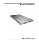
Apple Technician Guide Xserve (Early 2009) Updated: 2010-06-28
Apple Inc. © 2009 Apple Inc. All rights reserved. Under the copyright laws, this document may not be copied, in whole or in part, without the written consent of Apple. Every effort has been made to ensure that the information in this document is accurate. Apple is not responsible for printing or clerical errors. Apple 1 Infinite Loop Cupertino, CA 95014-2084 USA + 1 408 996 1010 www.apple.com Apple, the Apple logo, Mac, and Macintosh are trademarks of Apple Inc., registered in the U.S.
Xserve (Early 2009) Contents Basics Overview 9 Front View 10 Rear View 10 Serial Number Location 11 Hot-Pluggable SATA or SAS Drives 12 How to Identify Single- and Dual-Processor Configurations 13 Troubleshooting General Troubleshooting 15 Update System Software 15 Emerging Issues 15 Hardware vs.
Communications 67 Ethernet Port/Device Issues 67 Video 70 Video Distortion 70 No Video 71 Mechanical Issues: Thermal and Enclosure Failed or Fast Fans 72 72 Take Apart General Information 76 Orientation 76 Tools 76 How to Identify Single- and Dual-Processor Configurations 76 Mounting in a Rack 76 Icon Legend 77 Note on Illustrations 77 Apple Drive Module 78 Removal 79 Replacement 80 Power Supply 81 Removal 82 Replacement 82 Power Supply Blank 83 Removal 84 Replacement 84 Top Cover 85 Re
Memory Slot Utility 95 Replacement 96 Memory Configuration 96 PCI-E Riser Cards 97 Removal 98 Replacement 98 PCI-E Expansion Cards 99 Removal 100 Replacement 101 Optical Drive 102 Removal 103 Replacement 104 Airflow Duct 105 Removal 106 Replacement 107 Fan Array 108 Removal 109 Replacement 109 Battery 110 Removal 111 Replacement 111 Front Panel Cable 112 Removal 113 Replacement 113 Backplane-to-Logic Board I/O Cable Removal 115 Replacement 115 Optical Drive Cable 117 Removal 118 Rep
Replacement 126 Front Panel Buttons 127 Removal 128 Replacement 128 Light Pipe 129 Removal 130 Replacement 130 Front Panel Board 131 Removal 132 Replacement 132 Drive Interconnect Backplane 133 Removal 134 Replacement 134 Xserve RAID Card 136 Removal 137 Replacement 138 Power Distribution Board 139 Removal 140 Replacement 140 Power Distribution Board Cable Removal 142 Replacement 142 Xserve RAID Card Battery 143 Removal 144 Replacement 144 Processor Heat Sink 145 Removal 146 Replac
Removal 160 Replacement 160 ID Tab 161 Removal 162 Replacement 162 Enclosure 163 Removal 164 Replacement 164 Views Exploded View Feedback 168 166
Apple Technician Guide Basics Xserve (Early 2009) © 2009 Apple Inc. All rights reserved.
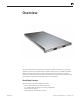
Overview The Xserve (Early 2009) rack-optimized server features single or dual Quad-Core Intel Xeon “Nehalem” processors, integrated memory controllers featuring up to 12 DIMMs of 1066MHz DDR3 ECC RAM, three hot-plug drive bays supporting SATA or SAS Apple Drive Modules, support for a Solid-State Drive (SSD) boot drive, dual x16 PCI Express 2.0 slots, NVIDIA GeForce GT 120 graphics subsystem and integrated lights-out management.
Front View On/standby button and light Drive module status light Enclosure lock and status light Drive module activity light Ethernet link light (Port 2) System identifier button/light USB 2.
Serial Number Location The serial number is located at the rear of the unit: on the ID Tab.
Hot-Pluggable SATA or SAS Drives The server includes three hard drive bays at the front of the Xserve. All bays support Apple qualified hot-pluggable Apple Serial ATA (SATA) or Serial Attached SCSI (SAS) drive modules. Xserve drive bays support qualified Apple Drive Modules with Apple qualified hard drives and firmware only. Drive bays not configured with an Apple Drive Module ship with a nonfunctional blank drive carrier which do not support third-party hard drive installation.
Power Supply Redundancy The Xserve (Early 2009) supports up to two power supply modules for redundancy. There are two power supply bays in the rear of the enclosure. You can replace or install a power supply from the back panel without removing the Xserve from the rack. If the Xserve has two power supplies, they are hot-swappable; the Xserve will continue to operate using only one supply while the second is removed.
Apple Technician Guide Troubleshooting Xserve (Early 2009) © 2009 Apple Inc. All rights reserved.
General Troubleshooting Update System Software Important: Whenever possible before beginning troubleshooting, ensure the latest software and firmware updates have been applied. Troubleshooting Theory For general information on troubleshooting theory, refer to: http://service.info.apple.com/service_training/en/006/troubleshoot/index.php?page=intro Emerging Issues For the latest on troubleshooting issues, refer to: http://support.apple.
Xserve Firmware Updates Firmware is the name given to software that is written into memory circuits, such as flash memory, that will hold the software code indefinitely, even when power is removed from the hardware. Firmware on Intel Mac computers is designed to be updated if necessary through a software update. EFI and SMC firmware is stored on the Xserve (Early 2009) backplane board. EFI firmware updates update the Boot ROM, and SMC updates update the System Management Controller firmware.
DIMMs must fit these specifications: • PC3-8500,1066 MHz, DDR3 SDRAM UDIMMs • 72-bit wide, 240-pin modules • 36 memory ICs maximum per UDIMM • Error-correcting code (ECC) For proper operation of Xserve (Early 2009) computers, Apple recommends using only Appleapproved DIMMs. Refer to GSX for Apple DIMM service part numbers. Memory from older Xserve computers is not compatible with Xserve (Early 2009). Single Processor Single-processor (quad-core) computers have six memory slots.
Dual Processor Dual-processor (eight-core) computers have twelve memory slots. You can install 1 GB, 2 GB, or 4 GB DIMMs for a total of up to 48 GB of memory. You can install different size DIMMs. in Xserve (Early 2009) However, for best performance, Apple recommends you install equal-size DIMMs (all 1, 2, or 4 GB) filling the slots in the order listed in this table.
Memory Slot Utility If you install different size DIMMs in single-processor or dual-processor computers, follow the order in the tables above. If the DIMM configuration you install doesn’t provide optimized performance, the Memory Slot Utility will appear on screen and recommend an improved configuration. To use the Memory Slot Utility again, go to /System/Library/Core Services.
Example of Memory Slot Utility Screen for Dual-Processor Computer 2010-06-28 Xserve (Early 2009) General Troubleshooting — Memory Configuration 20
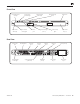
Block Diagram 2010-06-28 Xserve (Early 2009) General Troubleshooting — Block Diagram 21
Diagnostic LEDs Logic Board Diagnostic LEDs The Xserve (Early 2009) logic board includes a set of LEDs to help service providers troubleshoot the computer. The LEDs are located on the logic board below the DIMM connectors, at the rear of the unit, to the left side of the unit (looking from the back), and on the Drive Interconnect Backplane or Xserve RAID Card. Some tips: • You must remove the unit from its rack and place it on a sold surface with its cover removed in order to view these LEDs.
1. System State LEDs Use the following table to interpret the LEDs.
2. CPU Error LEDs Use the following table to interpret the LEDs.
Platform Reset Normally remains on during standby. This LED flashes on (yellow) briefly at power-on. LED should turn off as system powers up and begins to execute instructions. Overtemp LEDs Normally off. These LEDs come on if an error occurs. If LED is solidly on, it may indicate a processor over-temperature condition. Initial processor over-temperature can cause symptoms such as sluggish computer performance. Chronic processor over-temperature can cause the computer to hang completely.
$Bx = 1 0 1 1 X X X X = All $Bx codes below are memory init codes (x may be any code 0 - F) $BF = 1 0 0 1 1 1 1 1 = If the unit does not progress past any $Bx memory init codes, this could indicate a memory issue regardless of whether DIMM diagnostic error LEDs are ON or not. $12 = 0 0 0 1 0 0 1 0 = After memory initialization has successfully completed $51 = 0 1 0 1 0 0 0 1 = Video driver enabled beyond this point. Attached display should be displaying an image now.
5 & 6. Memory Diagnostic LEDs (A1 - A6 and B1 - B6) This group of LEDs will normally remain OFF during power-on and throughout normal operation. If any of these LEDs come ON RED, this indicates that the corresponding DIMM (or its slot) may be faulty. To verify whether the fault lies with the DIMM or the slot, power down the unit and move the DIMM to another slot. If the DIMM is faulty, the LED adjacent to its new slot should come ON RED when power is reapplied.
7. Reset Buttons System Management Controller (SMC) Reset The System Management Controller (SMC) is a chip on the logic board that controls all power functions for the Xserve. If the Xserve is experiencing any power issue, resetting the SMC may resolve it.
5. Press the power button to start up the Xserve. Power ON / OFF Button Behaves exactly like the front panel power button, and can be used as an alternate way to turn the unit on and off if needed. Reset Buttons When pressed, resets CPUs regardless of what is currently running. This reset overrides all software processes and restarts the system. Use with caution as this form of reset may corrupt software or files on a drive.
bay and the controller has recognized this event. The LED will turn ON GREEN again when the corresponding drive module has been removed from its bay. Since there are only three drive bays, the fourth I/O channel and LED are not used and should remain ON GREEN during normal operation. When you power-on the system, you should see the following activity sequence on these LEDs: 2010-06-28 1. The entire group of eight LEDs should come ON solid GREEN when power is applied and remain on for a few seconds. 2.
Symptom Charts Follow the steps in the order indicated below. If an action resolves the issue, retest the system to verify. If the issue persists after retesting, return to step 1. Startup and Power Issues No Power / Dead Unit Unlikely cause: Optical drive, hard drive(s), fan array, memory, RAID battery Quick Check 2010-06-28 Symptom Quick Check No Power / Dead Unit • No fan or drive module spin • No LED activity 1. Check the front panel on/standby light.
Deep Dive Check 2010-06-28 Result Action 1. Press the SMC Reset button on the logic board to reset the SMC. Verify that the Xserve powers on Yes Issue resolved. No Go to Step 2 2. Check internal diagnostic LEDs. Go to diagnostic LED section for more information. Verify that the Xserve powers on. Yes Issue resolved. No Go to Step 3 3. Remove all three drive modules and press the power button. Verify that the Xserve powers on. Yes Suspect drive module(s) as cause.
2010-06-28 10. Verify all cable connections to the logic board and drive interconnect backplane are secure. Yes Go to Step 11 No Ensure all cable connections to the logic board and drive interconnect backplane are secure. Go to Step 11 11. Replace the power supply. Verify that the Xserve powers on. Yes Issue resolved. No Go to Step 12 12. Replace the power distribution board. Verify that the Xserve powers on. Yes Issue resolved. No Go to Step 13 13. Replace the front panel board cable.
Burnt Smell or Odor Quick Check Symptom Quick Check Burnt Smell / Odor • System emits an odor or smell of smoke. 1. Disconnect the power cord from the system. 2. Identify the source of the odor. 3. Some odors may be present when operating normally. Refer to http://support.apple.com/kb/ TA22044. Some visual clues may include brown marks on PCBs, and component damage i.e. transistors, ICs, inductors, capacitors, resistors etc.
Deep Dive Check Result 1. Verify source of the odor ie foreign contaminant such as fluid ingress, dust, hair etc 2010-06-28 Action Yes Cleanup foreign contaminant, replace any affected modules. Foreign contaminants are not covered by Apple warranties No Go to step 2 2. Inspect PCB’s and components for indications of a thermal event Yes Replace any affected modules No Go to step 3 3. Verify System is functioning correctly Yes Some odors may be present when operating normally.
Won’t Start Up / No Video/ LED On Unlikely cause: Fan array, front panel board, memory, optical drive, power distribution board, power supply, RAID battery Quick Check Symptom Won’t Startup / No Video / LED On • Xserve begins to power up but does not boot • Fan array and hard drive are spinning • Power LED is illuminated • No activity lights • No video on connected external display Quick Check 1. Confirm the system configuration supports an external display.
4. Reconnect each one at a time, verifying unit operation as drive module is reinstalled. Verify Xserve boots from known good external bootable device. Yes Repeat Step 4 until the drive module is isolated. No Failed drive module. Replace drive module. Issue resolved. 5. Remove both internal PCI riser cards and any installed expansion cards and press the power button. Verify Xserve boots from known good external bootable device. Yes Suspect PCI card(s) and/or riser card(s) as cause.
13. Reinstall user’s original startup drive module. Verify Xserve boots from user’s original startup drive module. Yes Issue resolved. No Replace user’s original startup drive module. Start up from Server Install Disc and install server OS onto user’s replacement startup drive module. Verify Xserve boots from replacement startup drive module. Issue resolved.
2. Reseat the front panel board and its cable connectors. Verify Xserve boots from user’s original startup drive module. Yes Issue resolved. No Go to Step 3 3. Replace front panel board. Verify Xserve boots from user’s original startup drive module. Yes Issue resolved. No Go to Step 4 4. Reinstall original front panel board. Remove and re-seat logic board to enure rear panel System Identifier button is not stuck in. Verify Xserve boots from user’s original startup drive module.
Deep Dive Check 1. 2010-06-28 Result Action Code Press the SMC Reset button on the logic board to reset the SMC. Verify Xserve no longer shuts down after starting up. Yes Issue resolved. No Go to Step 2 2. Check internal diagnostic LEDs. Go to diagnostic LED section for more information. Follow recommendations therein. Verify Xserve no longer shuts down after starting up. Yes Issue resolved. No Go to Step 3 3. Check that the fan array connector is connected and the fan array is operational.
Kernel Panic/System Crashes Quick Check Symptom Quick Check Memory Issues/Kernel panic and freezes • Unit has kernel panic or freezes on startup or when operating • Memory not recognized in System Profiler or in Memory Slot Utility • Fans running fast 1. After power ON, verify Front Panel power LED illuminated, and not flashing any error sequences indicating a memory failure. 2. Verify with known good and compatible memory DIMMs. Memory from older computers is not compatible and cannot be used. 3.
3. Disconnect all peripherals and expansion cards. Verify that Xserve starts without issue. 4. Verify all fans in fan array are spinning and there is adequate airflow inside and around the Xserve 5. Attempt to boot with original install media or from an external hard drive with compatible OS X installed. Verify the Xserve is able to successfully boot to the Finder. 6. Inspect if any memory error LED’s illuminated. Install 1 only known good compatible memory DIMM in memory slot#1.
Uncategorized Symptom Quick Check Symptom Quick Check Uncategorized Symptom Verify whether existing symptom code applies to the issue reported by the user. If not, document reported symptoms and send feedback to smfeedback@apple. com stating that suitable symptom code could not be found.
Mass Storage Apple Drive Module Read/Write Issue Unlikely cause: Optical drive, logic board, processors. Quick Check Symptom Quick Check Read/Write Issues / Bad Blocks / Drive Formatting Issues • Cannot save documents • Read/Write error message • Hang when accessing or saving data. • Intermittent unexpected hanging • Slow drive module performance 1. Reseat any affected drives into other bays. 2. Boot from Install DVD. Verify S.M.A.R.T. status of the affected hard drive using Disk Utility. 3.
4. Run Repair Disk on the volume using Disk Utility. Did Disk Utility mount and repair volume successfully? 5. Remove the original drive module from the Xserve and inspect it for any damage to its connector or the connector in that drive bay of the Xserve. Is damage present? 6. Substitute a known-good drive module. Format this drive module using Disk Utility and select ‘zero all data’ option to remap bad blocks.
8. Replace the Backplane-toLogic Board I/O Cable. Format known-good drive module using Disk Utility and select ‘zero all data’ option to remap bad blocks. Verify this drive module formats successfully with no significant errors or large numbers of bad blocks using Disk Utility log. Yes Issue resolved. X03 No Go to Step 9 9. Replace Drive Interconnect Backplane. Format knowngood drive module using Disk Utility and select ‘zero all data’ option to remap bad blocks.
Deep Dive Check 1. 2010-06-28 Press the SMC Reset button on the logic board to reset the SMC. Verify that the Xserve now recognizes the drive module. Result Action Yes Issue resolved. No Go to Step 2 2. Check internal diagnostic LEDs. Go to diagnostic LED section for more information. Verify that the Xserve now recognizes the drive module. Yes Issue resolved. No Go to Step 3 3. Start up from Install disc and launch Disk Utility.
8. Remove and re-seat Drive Interconnect Backplane and retest. Verify that the Xserve now recognizes the drive module. Yes Issue resolved. X03 No Go to Step 9 9. Replace the Backplane-toLogic Board I/O Cable and retest. Verify that the Xserve now recognizes the drive module. Yes Issue resolved. No Reinstall the Backplane-toLogic Board I/O Cable. Go to Step 10 10. Replace Drive Interconnect Backplane and retest. Verify that the Xserve now recognizes the drive module. Yes Issue resolved.
Deep Dive Check 1. Action Boot from Install DVD and launch Disk Utility. Is the affected drive module available for Disk Utility to repair? Yes Go to Step 2 No Replace affected drive module or branch to “Drive module not recognized/mount” troubleshoot guide 2. Repair the affected drive module using Disk Utility and verify it completed successfully Yes Go to Step 3 No Go to Step 4 Yes Fan noise or Optical Drive noise likely to be the cause.
Optical Drive Read/Write Issue Quick Check Symptom Quick Check Optical Drive Read/Write Data Error • Errors when writing optical media • Errors when reading optical media • Hang when accessing or preparing to write data. 1. Test optical media in another drive of the same type in same type of machine to rule out the media issue. 2. For write issues, check with known-good media that performs well in another computer and optical drive of the same type. 3. Check both CD and DVD media.
5. Install and test with replacement optical drive SATA flex cable. Verify that media is now recognized and reads reliably. Yes Cable change resolved issue. X03 No Replace the optical drive. (Mechanical damage to optical drive, if found) J01 (J05) 6. Test write data to compatible CD and DVD media. Verify burned media is recognized and reads reliably. Yes Issue resolved. No Replace the optical drive.
2. Verify all connections between logic board, flex cable, optical drive are secure. Visually inspect cables and connectors for any debris, damage, or bent pins. Is optical drive now listed in System Profiler? Yes Issue resolved. No Replace any damaged cables and retest. If connections are good and with no visible cable damage, go to step 3. 3. Disconnect optical drive by lifting SATA cable at logic board and connecting a known-good drive.
Deep Dive Check 1. 2010-06-28 Is optical drive constantly seeking or cycling eject mechanism without an optical disc installed? Optical drive should perform only one reset sequence and rest idle, ready for media. Result Action Code Yes Continue and verify with media, Go to Step 2. No Replace optical drive if continuous activity occurs with no disc installed. 2. Insert known good data CD.
7. Disc spin should cease 30 seconds after mounting data CD on desktop. Media may be mounting on a defective internal spindle hub. Is the noise related to disc spin? Yes Replace optical drive. No Noise does not appear to be related to optical drive. J04 Optical Drive Not Performing to Specs Quick Check Symptom Quick Check Optical Drive Not Performing to Spec • Read of write speeds slower than expected. 1.
3. Disconnect optical drive by lifting SATA cable at logic board and connecting a known-good drive. Verify that media is now recognized and reads reliably. Yes SATA port functional, reconnect user’s optical drive & SATA cable. Go to Step 4. No Replace logic board. M19 4. Install and test with replacement optical drive SATA flex cable. Verify that media is now recognized and reads reliably. Yes Cable change resolved issue. X03 No Replace optical drive.
2. Verify the optical drive listed in the device tree for ATA devices in System Profiler? Yes Optical drive has power, inspect disc acceptance. Re-inspect for non standard media. No Inspect and reseat cables. Go to step 3. 3. Verify all cable connections between optical drive and logic board are secure. Visually inspect cables and connectors for any debris, damage, or bent pins. Is optical drive now listed in System Profiler? Yes Optical drive has power, inspect disc acceptance.
Deep Dive Check 1. Verify that the bezel over the slot is not bent. If it is, gently bend it back into position. Action Yes Issue resolved. No Go to step 2. 2. Verify the disc is not the wrong size. Refer to article 58641 “Macintosh: Using Nonstandard Discs in disc-ROM or DVD-ROM Drives.” Yes Remove irregular shaped media and retest. No Go to step 3. 3. Reseat the optical drive cable at both connectors. Yes Issue resolved. No Go to step 4. 4. Replace the optical drive cable.
RAID Battery Not Charging Quick Check Symptom Quick Check RAID Battery Will Not Charge • The following messages may be displayed in RAID Utility: 1. If write caches are disabled: The RAID card backup battery may not be fully charged. To protect your data, the RAID card automatically disables write caching whenever the battery is not fully charged. Once every three months the RAID card reconditions the battery by completely discharging and then recharging it. 2.
Deep Dive Check 1. Disconnect RAID battery connector from drive interconnect backplane. Using a multimeter set to measure DC voltage in the 4 volt range, connect the multimeter probes to the extreme end connector pins of the RAID battery connector. Result Action Yes Go to Step 2 2. Does the multimeter measure at least 3.5 VDC? No Replace battery. Go to Step 2 3. Reconnect RAID battery connector to drive interconnect backplane.
Uncategorized Symptom Quick Check Symptom Quick Check Uncategorized Symptom Verify whether existing symptom code applies to the issue reported by the user. If not, document reported symptoms and send feedback to smfeedback@apple. com stating that suitable symptom code could not be found.
Input/Output Devices Rear USB Port Does Not Recognize Known Devices Quick Check Symptom Quick Check Rear USB Port Does Not Recognize Known Devices • USB devices not recognized on the rear USB port. 1. If the Xserve is locked, unlock it. 2. Check the for latest software updates for Apple and especially third party devices. 3. Use System Profiler to verify the System recognizes each of the USB buses in the USB device tree. 4. Test both rear ports with known good Apple keyboard or mouse. 5.
3. Reset SMC. Verify each of the USB buses are recognized, and a known good connected USB device is recognized? Yes Issue resolved. Issue maybe caused by another peripheral device. No Replace Logic Board. M15 Front USB Port Does Not Recognize Known Devices Quick Check Symptom Quick Check Front USB Port Does Not Recognizing Known Devices • USB devices not recognized on the front USB port. 1. If the Xserve is locked, unlock it. 2.
3. Reset SMC. Verify each of the USB buses are recognized, and a known good connected USB device is recognized? Yes Issue resolved. Issue maybe caused by another peripheral device. No Go to step 4. 4. Reseat the Front Panel Board cable. Yes Issue resolved. No Replace Front Panel Board. M15 N08 FireWire Port Does Not Recognize Known Devices Quick Check Symptom Quick Check FireWire Port Does Not Recognize Known Devices • FireWire devices not recognized. 1. If the Xserve is locked, unlock it.
2. Verify the FireWire ports are free from contaminants and debris. Yes Go to step 3 No Remove contaminants and debris. Replace affected modules if necessary. Defects caused by contaminants or debris are not covered by Apple warranty. Go to step 3. 3. Reset SMC. Verify each of the FireWire busses are recognized, and a known good connected Firewire device is recognized? Yes Issue resolved. Issue maybe caused by another peripheral device. No Replace Logic Board.
Deep Dive Check 1. Result Does the expansion card meet the requirements for the slot in which it is being used? Yes Go to step 2. No Refer to product specifications of Xserve then recommend the card be replaced with the proper specification type of model. Yes Issue resolved. No Go to step 3. Yes Issue resolved. No Go to step 4. 4. Reseat the PCI riser card into the logic board, and retest the card in the same slot. Yes Issue resolved. No Go to step 5. 5.
Uncategorized Symptom Quick Check Symptom Quick Check Uncategorized Symptom Verify whether existing symptom code applies to the issue reported by the user. If not, document reported symptoms and send feedback to smfeedback@apple. com stating that suitable symptom code could not be found.
Communications Ethernet Port/Device Issues Quick Check Symptom Quick Check Network Issues • Server cannot be seen on network • Slow network performance 1. Open the Network system preference pane and select the built-in Ethernet option. 2. If only one Ethernet port is in use, verify that it is the right hand (1) port. If it is not, move the Ethernet cable to the right hand (1) port. This is the primary (en0) port. 3. Boot the Xserve from the Installation disc.
2. Visually inspect Ethernet connector to ensure all pins will make physical contact with CAT5 or better network cable. 2010-06-28 Yes Ethernet interface contacts are good. Go to step 3. No Pins are damaged or bent flat, replace logic board. 3. Isolate OS by booting from original install media. Verify network link status active by using Network Utility on install DVD and looking for link LED adjacent to connected Ethernet port.
6. Verify Ethernet performance and reliability by starting up from a known-good OS install, and downloading a large file from a web site or file server. Yes If there is performance or connectivity issue isolated solely to the system under test, the problem may be the network environment. No repair is necessary. No If there are connection dropouts or poor performance not seen on a known-good test system, replace the logic board.
Video Video Distortion Quick Check Symptom Quick Check Video is distorted • Bad/Dim color • Lines or artifacts • Distortion/garbled video 1. Refer to the adjustments section of the owner’s manual for the external display. Adjust display as necessary. 2. Reseat the Mini DisplayPort adapter and cable connections. 3. Inspect the Mini DisplayPort adapter pins and replace the adapter if necessary. 4. Reset PRAM/NVRAM. (You must unlock the Xserve to perform) 5. Test with a known good display. 6.
No Video Quick Check Symptom Quick Check External display has no video, but activity lights flash at startup, drive operates, fan array is spinning, and power LED is illuminated. • Device has power and boots, but no video output 1. Confirm the system configuration supports an external display. Not all configurations do, although the Mini DisplayPort connector on the rear of the unit is present regardless.
Mechanical Issues: Thermal and Enclosure Failed or Fast Fans Quick Check Symptom Quick Check System Fast/Failed Fans • System feels very warm • Computer is sluggish • Fan(s) running fast • Fan(s) not running at all 1. Verify the System has adequate airflow around the enclosure, front and rear vents not blocked. 2. Verify the issue is not user perception - System functions correctly, and not running any warmer than expected. Compare to a similarly configured System.
2. Determine if there are runaway applications or processes consuming the CPU’s - Verify using ‘Activity Monitor’. Are any runaway applications or processes present? 2010-06-28 Yes The application or process may have crashed. Alternatively check with the software vendor for compatibility and software update. No There are no runaway applications or processes. Go to step 3. 3. Press the SMC Reset button on the logic board to reset the SMC.
6. Clear out any obstructions such as dust or internal cables from the fan array and heatsinks. Reseat fan array connections to drive interconnect backplane. Ensure no damage to heatsinks ie bent or crushed fins. Reseat CPU(s) and heatsink(s). Run Server Monitor and AXD to verify the thermal sensor and fan circuity is functioning correctly. Verify all fans are rotating at close to minimum speed within a few minutes after the system is idle.
Apple Technician Guide Take Apart Xserve (Early 2009) © 2008 Apple Inc. All rights reserved.
General Information Orientation For most take-apart procedures, Apple recommends removing the computer from the rack before removing or installing the part.
Icon Legend The following icons are used in this chapter: Icon Meaning Warning or caution Check; make sure you do this Challenging procedure; requires more thought and/or time until you are familiar with it Note on Illustrations Because a pre-production model was used for the illustrations in this manual, you may notice small differences between the image pictured and the computer you are servicing.
Apple Drive Module First Steps Caution: Make sure data is backed up before removing or replacing the drive. .
Removal 1 4 Make sure the locking mechanism is in the unlocked position. 2 Make sure the drive being replaced is not in use by any application and is not being shared by the Xserve. (See the Mac OS X Server documentation for information about shared drives.) 3 Unmount the drive (by using the command-line tools or by dragging the volume icon to the Trash.). Press the handle on the drive.
5 Grasp handle on the replacement drive. Pull module out of the Xserve. Replacement 1 Slide module into the bay until it is firmly seated. 2 Press the handle flush with the front panel. Replacement Note: If you replace the hard drive with a new one, format the new drive.
Power Supply First Steps Warning: If the Xserve has only one power supply, shutdown computer.
Removal 1 Unplug the power cord from the power supply. 2 Pull handle to release the power supply. 3 Slide out of the bay. Note: If the Xserve is already running on a second power supply, the status light on the new power supply turns green to indicate normal operation as it stars sharing the load. If the Xserve is not turned on, the status light blinks green when the power cord is plugged in to an outlet with power. Replacement 1 Pull handle on the new power supply.
Power Supply Blank First Steps • No first steps for this procedure.
Removal 1 Pull the handle to swing open the power supply blank. 2 Notice the hook that catches on the inside bottom of the power supply bay. 3 Open the power supply blank as far as it will go, and pull out the power supply blank. Replacement 1 Align the hook on the power supply blank with the catch inside the power supply bay.
Top Cover First Steps Write down the Xserve serial number. If the Xserve’s software must be setup after service is complete, the serial number will be required.
Removal 1 Shutdown the Xserve and wait a few moments for components to cool. 2 If the Xserve case is locked, use the Xserve Allen wrench to unlock the security lock on the front panel. 3 Unplug all cables from the Xserve.. 4 Loosen the thumbscrews at the back of the top cover and slide cover back and up to remove it. Replace 1 Replace and secure the cover. 2 Tighten the thumbscrews at the back of the top cover.
Solid State Drive First Steps Remove: • Top Cover Tools • • ESD wrist strap and mat Black stick 2010-06-28 Xserve (Early 2009) Take Apart — Solid State Drive 87
Removal 1 Disconnect the SSD cable from the Front Panel Board. 2 Gently press the two tabs out to release the drive. It may be helpful to use the black stick under the drive. Replacement 1 Note the orientation of the drive. The connector on the drive should be facing up. The label should face down. 2 The drive connector should be facing the front of the Xserve. 3 Place the SSD drive into the SSD drive carrier. 4 Connect the SSD cable to the front panel board.
Solid State Drive Cable First Steps Remove: • Top Cover • Solid State Drive .
Removal 1 Disconnect SolidState Drive cable from the Front Panel Board. 2 Lift the Kapton tape from the Solid-State Drive. 3 Using the black stick, gently flip up the locking lever. 4 Gently slide the SolidState Drive cable out of connector. Replacement 1 Slide connector into receptacle on the Solid-State Drive. 2 Lock down lever after inserting cable. 3 Replace Kapton tape over the connector on drive. 4 Connect the cable to the Front Panel Board.
Solid State Drive Carrier Note: Adhesive on the bottom side of the solid state drive carrier attaches it to the enclosure. Whenever you detach the carrier from the enclosure, you must install a replacement carrier (part number 922-8959). Otherwise, the used adhesive may not hold the carrier firmly in place. First Steps Remove: • Top Cover • Solid State Drive .
Removal 1 Gently lift the carrier from the adhesive on the enclosure. Replacement Note: The adhesive on the replacement carrier is located on the bottom of the carrier and covered by a protective film. 1 Peel off the film covering the carrier’s adhesive.
2 Position the carrier adhesive side down. Align the holes in the carrier with the four enclosure holes indicated and press down.
Memory First Steps Remove: • Top Cover Apple recommends that you use Apple-approved DIMMs. DIMMs from older Xserve systems are not compatible with this Xserve.
Removal 1 Open ejectors on DIMM slots.by pushing them out to the sides. 2 Holding the DIMM by edges, remove it from connector. 3 Do not touch the gold connectors. Warning: DIMMs may be very hot. Always wait 5-10 minutes for computer to cool down .before removing or installing memory . Memory Slot Utility 2010-06-28 If the DIMM configuration you install does not provide optimized performance, the Memory Slot Utility will appear on screen and recommend an improved configuration.
Replacement Replacement Note: The DIMM is designed to fit into the slot only one way. Be sure to align the notch on the DIMM with the slot. 1 Align.the notch on the DIMM with the slot. 2 Push both ends of DIMM down until ejectors snap back up into place. Memory Configuration Xserve (Early 2009) comes with a minimum of 3 GB of memory installed as three 1 GB unbuffered dual inline memory module (UDIMMs).
PCI-E Riser Cards First Steps Remove: • Top Cover Important: Before you begin this procedure, verify the Xserve is turned off and unplugged.
Removal 1 Loosen the two captive screws that secure the riser bracket to the back panel. 2 Carefully pull up on the bracket and riser to disconnect from the logic board. 3 If you are removing a blank riser card to install a card do the following: • Remove the screw on the riser bracket • Seat the PCI card in the riser slot and replace the screw to secure in the riser.
PCI-E Expansion Cards First Steps Remove: • Top Cover • PCI-E Riser Cards Important: Before you begin this procedure, verify the Xserve is turned off and unplugged.
Removal 1 Loosen the two captive screws that secure the riser bracket to the back panel. 2 Carefully pull up on the bracket and riser., with the expansion card still attached to disconnect from the logic board. 3 Tilt the expansion card up so the port clears the enclosure, and remove the card from the Xserve. 4 Remove the screw that secures the expansion card to the riser. 5 Gently separate the card and riser. Warning: When removing or installing an expansion card, handle it by the edges.
Replacement 1 Seat the expansion card in the riser slot. 2 Replace the screw to secure the card in the riser. 3 Align the riser with the slot on the logic board. 4 Press down to seat the card. 5 Tighten the captive screws to secure the riser bracket to the back panel.
Optical Drive First Steps Remove: • Top Cover Tools • • ESD wrist strap and mat Phillips #0 screwdriver 2010-06-28 Xserve (Early 2009) Take Apart — Optical Drive 102
Removal 1 Disconnect optical drive cable from drive. 2 Rotate the optical drive clip clockwise to release it. 3 Placing your thumbs on either side of the drive, slide the drive back from the front bezel. 4 Lift drive out of the Xserve. Important: When removing or replacing the optical drive, do not put pressure on the top of the drive of front bezel of the optical drive slot.
5 Remove the mounting screw from left and right bracket. Replacement 1 Transfer the left and right brackets to the new drive. 2 Place the drive into the Xserve. 3 Placing your thumbs on either side of the drive, slide the drive forward towards the front bezel. 4 Rotate the optical drive clip counterclockwise to secure it.
Airflow Duct First Steps Remove: • Top Cover Tools • • ESD wrist strap and mat Phillips #1 screwdriver 2010-06-28 Xserve (Early 2009) Take Apart — Airflow Duct 105
Removal 1 Loosen the five screws that fasten the airflow duct to the fan array. 2 Pull up on either side of the airflow duct, and lift straight up. Removal Note: Remove screws in the order shown. Do not overtighten screws. Caution: Do not completely remove the screws from the airflow duct. Tiny black rubber washers hold these screws captive on the underside of the airflow duct. If the screws are completely removed, these rubber washers can easily fall into the enclosure and become lost.
Replacement 1 Be sure to route both the front panel cable and the backplane-tologic board I/O cable inside the channel under the duct. 2 Ensure the airflow duct fits flush and does not protrude above the enclosure. 3 Tighten the five Phillips screws that fasten the airflow duct to the fan array. Removal Note: Remove screws in the order shown. Do not overtighten screws.
Fan Array First Steps Remove: • Top Cover • Airflow Duct Tools • • ESD wrist strap and mat Phillips #1 screwdriver 2010-06-28 Product Name Take Apart — Fan Array 108
Removal 1 Loosen the two thumbscrews. You may need to use a Phillip #1 screwdriver. Removal Note: The thumbscrews are captive; you cannot remove them. 2 Carefully rotate the fan array as shown to disconnect it from power distribution board. 3 Lift the fan array to remove it from the Xserve. Removal Note: You may need to move the front panel cable slightly out of the way during removal or replacement. Be careful to not pinch the cable between the fan array and another surface.
Battery First Steps Remove: • Top Cover • Airflow Duct Tools • • ESD wrist strap and mat Black stick 2010-06-28 Xserve (Early 2009) Take Apart — Battery 110
Removal 1 Insert the black nylon tool under the battery to ease the grip between the spring and holder. 2 Slide the battery out to remove from the holder. Warning: To avoid risk of explosion, replace battery only with type BR2032. Replacement 1 Insert the replacement battery in the holder. 2 Remove the insulated tab. 3 Ensure the positive side (+) is up and the negative side down. Important: Dispose of the battery according to manufacturer’s instructions and your local environmental laws..
Front Panel Cable First Steps Remove: • Top Cover • Airflow Duct • PCI-E Riser Cards • PCI-E Expansion Cards Tools • • ESD wrist strap and mat Black stick 2010-06-28 Xserve (Early 2009) Take Apart — Front Panel Cable 112
Removal 1 Release the locking levers on the cable connectors. Removal Note: The black stick may help in unlocking the levers on the cable connectors. 2 Disconnect the front panel board cable from the front panel board. 3 Disconnect cable from the logic board. 4 Remove cable from the Xserve. Replacement 1 Connect the cable to the logic board. 2 Connect the cable to the front panel board..
Backplane-to-Logic Board I/O Cable First Steps Remove: • Top Cover • Airflow Duct Tools • • ESD wrist strap and mat Black stick 2010-06-28 Xserve (Early 2009) Take Apart — Backplane-to-Logic Board I/O Cable 114
Removal 1 Disconnect the backplane-logic board cable from logic board. 2 Disconnect the backplane-to-logic board cable from the drive interconnect backplane. 3 Remove cable from Xserve. Replacement Replacement Note: Before installing the cable, fold it to a 90-degree angle along its creases.
1 Connect the cable to the logic board first. 2 Press adhesive section of cable onto enclosure. 3 Connect the cable to the backplane. Caution: Make sure the cable is fully seated.
Optical Drive Cable First Steps Remove: • Top Cover • Airflow Duct • Fan Array Warning: The optical drive cable is attached to the enclosure with an adhesive on the underside of the cable.
Removal 1 Disconnect the optical drive cable from the optical drive. 2 Disconnect the optical drive from the logic board. 3 Carefully pry the cable’s adhesive from the enclosure. 4 Remove cable from the Xserve.
Replacement Replacement Note: Fold the replacement optical drive cable to 90-degree angles along its creases. 1 Connect the cable to the logic board. 2 Press the adhesive section of the cable onto the enclosure 3 Connect the other end of the cable to the optical drive.
Locking Mechanism Rod First Steps Remove: • Top Cover Tools • • ESD wrist strap and mat Black stick 2010-06-28 Xserve (Early 2009) Take Apart — Locking Mechanism Rod 120
Removal 1 Gently pull back latch to release the gear of the locking mechanism rod. 2 Tilt up the gear end of the rod. 3 Remove the rod from the Xserve. Removal Note: If you are replacing the plastic gear on the end of the rod, slide the gear off the rod. Replacement 1 Slide the rod onto the notched end of the locking rod. 2 Align the narrow end of the gear with the end of the rod 3 Insert the key-hole end into the port on the front bezel.
Front Bezel Brackets First Steps Remove: • Top Cover Tools • • ESD wrist strap and mat Phillips #2 screwdriver 2010-06-28 Xserve (Early 2009) Take Apart — Front Bezel Brackets 122
Removal 1 Remove the four identical 4-mm long screws. 2 Remove the two brackets. Replacement 1 Position the right replacement bracket on the Xserve. 2 Install two 4-mm long screws. 3 Repeat for the left bracket.
Front Bezel Assembly First Steps Remove: • Apple Drive Module • Power Supply • Top Cover • Front Bezel Brackets Tools • • ESD wrist strap and mat Phillips #2 screwdriver 2010-06-28 Xserve (Early 2009) Take Apart — Front Bezel Assembly 124
Removal 1 Remove the four 4-mm long screws and two brackets from behind the front bezel brackets. 2 Remove the 8-mm long center screw. 3 Gently pull the front bezel forward and remove from the Xserve. Important: Do not put pressure on the top of the bezel over the optical drive slot.
Replacement 1 Leave the power and system identifier buttons on the front panel board. 2 Align the buttons with the front panel openings. 3 Secure the light pipe in the front bezel. Align the pins to the front bezel and insert into the slot. 4 Place the front bezel on the server, matching the opening with the buttons and ports. 5 Replace the bezel brackets, four 4-mm long screws, and 8-mm long center screw.
Front Panel Buttons First Steps Remove: • Top Cover • Front Bezel Brackets • Front Bezel Assembly Tools • • ESD wrist strap and mat Phillips #2 screwdriver 2010-06-28 Xserve (Early 2009) Take Apart — Front Panel Buttons 127
Removal 1 Hold the power or system identifier button by the plastic tab. 2 Lift straight up and remove from the front bezel. Removal Note: The face of the button is loosely attached to the button LED. Replacement 1 Position the replacement button in the front bezel. 2 Verify the buttons are in the correct position.
Light Pipe First Steps Remove: • Top Cover • Front Bezel Brackets • Front Bezel Assembly The Light Pipe may come out with the front bezel assembly.
Removal 1 Grasp the edges of the light pipe. 2 Pull light pipe out of the front bezel assembly. Replacement 1 Align the pins on the replacement light pipe with pin opening on front bezel assembly. 2 Gently press the light pipe into the front bezel assembly. 3 Replace front bezel assembly. 4 Replace the two front bezel brackets.
Front Panel Board First Steps Remove: • Top Cover • Locking Mechanism Rod • Front Panel Board Cable • Solid State Drive Tools • • ESD wrist strap and mat Phillips #1 screwdriver 2010-06-28 Xserve (Early 2009) Take Apart — Front Panel Board 131
Removal 1 Release the two locking levers on the connector and disconnect cable. 2 Remove the two 6-mm screws. 3 Slide the board back slightly and release the two clips on either side. 4 Tilt board up and remove. Replacement 1 Tilt board up slightly and insert board into clips. 2 Slide board forward into front panel assembly. 3 Replace the two 6-mm screws and cable.
Drive Interconnect Backplane First Steps Remove: • Apple Drive Module • Power Supply • Top Cover • Airflow Duct • Fan Array • Power Distribution Cable .
Removal 1 Loosen the captive thumbscrew. 2 Shift the backplane to the right (towards the enclosure) until it clears the stands. 3 Slightly tilt up the backplane toward the logic board. Removal Note: Do not let the backplane components come into contact with the standoffs or the enclosure as you remove the backplane. Replacement 1 Lower the backplane into the enclosure at a slight angle.
2 Rotate the backplane downward and over the four standoffs. 3 Slide the backplane in the direction shown to seat the backplane into enclosure. 4 Tighten the captive thumbscrew. 5 Connect the backplane-to-logic board cable. Verify cable is firmly seated. 6 Connect the front panel board cable to the front panel board.
Xserve RAID Card First Steps Remove: • Apple Drive Module • Power Supply • Top Cover • Airflow Duct • Fan Array • Power Distribution Board Cable • Front Panel Board Cable • Backplane-to-Logic Board Cable Tools • • ESD wrist strap and mat Phillips #2 screwdriver 2010-06-28 Xserve (Early 2009) Take Apart — Xserve RAID Card 136
Removal 1 Remove power distribution cable from Xserve RAID Card. 2 Disconnect the Backplane to Logic Board cable. 3 Disconnect the Xserve RAID Card battery cable from Xserve RAID Card. 4 Loosen the captive thumbscrew. 5 Shift the backplane to the right (towards the enclosure) until it clears the stands. 6 Slightly tilt up the backplane toward the logic board. Removal Note: Do not let the RAID card components come into contact with the standoffs or the enclosure.
Replacement 1 Lower the backplane into the enclosure at a slight angle. Replacement Note: Do not let the RAID card components come into contact with the standoffs or the enclosure. 2 Rotate the backplane downward and over the four standoffs. 3 Slide the backplane to the right in the direction shown to seat the backplane into enclosure. 4 Tighten the captive thumbscrew. 5 Connect the backplane-to-logic board cable. Verify cable is firmly seated.
Power Distribution Board First Steps Remove: • Apple Drive Module • Power Supply • Top Cover • Airflow Duct • Fan Array • Drive Interconnect Backplane • Power Distribution Board Cable Tools • • ESD wrist strap and mat Phillips #2 screwdriver 2010-06-28 Xserve (Early 2009) Take Apart — Power Distribution Board 139
Removal 1 Release the captive thumbscrew that secures the power distribution board to the enclosure. Removal Note: Captive thumbscrew may be tight, use the Phillips screwdriver to assist in removal. 2 Pull the board toward the left towards the enclosure in the direction shown. 3 Lift up the board and remove it from the enclosure. Replacement 1 Lower the board into the enclosure. 2 Pull the board to the right to lock the board in place.
Power Distribution Board Cable First Steps Remove: • Top Cover Caution: The power distribution board connectors are very tight and can be difficult to disconnect.. Use a nylon black stick to gently yet firmly pry outwards on the cable connector while depressing the latch with your thumb and forefinger.
Removal 1 Disconnect the power distribution board cable on the drive interconnect backplane. 2 Disconnect the power distribution board cable from the power distribution board. 3 Remove from the Xserve. Replacement 1 Connect the power distribution board cable to the power distribution board. 2 Connect the power distribution board cable to the drive interconnect backplane.
Xserve RAID Card Battery First Steps Remove: • Apple Drive Module • Power Supply • Top Cover • Airflow Duct • Fan Array • Power Distribution Board Cable • Xserve RAID Card • Power Distribution Board Tools • ESD wrist strap and mat 2010-06-28 Xserve (Early 2009) Take Apart — Xserve RAID Card Battery 143
Removal 1 Lift the Xserve RAID Card battery straight up off its three mounting posts. 2 Remove the battery from the enclosure. Removal Note: Adhesive on the underside of the battery holds it in place on the enclosure floor. Replacement 1 Remove the protective film covering the adhesive on the underside of battery. 2 Lower the battery into place on its three mounting posts. Important: Do not drop, disassemble, crush, incinerate, or expose the battery to temperatures above 212° F (100° C).
Processor Heat Sink First Steps Remove: • Top Cover • Airflow Duct Note: The thermal bond between the processor and heat sink requires thermal grease. You must replace the thermal grease every time your remove the processor and processor heat sink.
Removal 1 Loosen the four captive screws securing the heat sink to the processor. Caution: Each heat sink is connected to the logic board by a small 2-pin thermal sensor cable. Lifting the heat sink too quickly can damage the cable or connector. Because of the tight thermal bond between the processor and the heat sink, be cautious when removing. Do not pull on the cable as you lift the heat sink. 2 Pull the connector, not the cable, to disconnect the sensor cable from the logic board.
3 Handle the heat sink from the side slotted sides, not the smooth sides. Grasping from the smooth sides can compress the ribs causing permanent damage. 4 Lift the heat sink straight up and out of the enclosure. 5 Gently twist the processor and heat sink in opposite directions. Important: Hold the processor by three corners when removing or replacing the processor. Do not touch the gold pins on the processor or processor socket on the logic board.
Replacement Important: The thermal bond between the processor and heat sink requires thermal grease for proper operation. You must replace the thermal grease on the processor each time you remove or replace the heat sink. Clean the processor and apply new grease as follows 1 Always hold the processor by three corners. 2 Clean off any existing thermal grease on the heat sink and processor using alcohol wipes provided with the replacement part. 3 Using the syringe, apply 0.
Processor First Steps Remove: • Top Cover • Airflow Duct • Processor Heat Sink Note: The thermal bond between the processor and heat sink requires thermal grease. You must replace the thermal grease every time your remove the processor heat sink Note: This procedure applies to the Xserve (Early 2009) single and dual-processor configurations. Important: Xserve (Early 2009) requires thermal grease for proper operation.
Removal 1 Carefully remove the processor from the heat sink by twisting the heat sink and processor in opposite directions. Important: Place the CPU socket cover over the processor slot on the logic board after processor is removed. 2 Hold the processor by the three corners. Be extremely careful not to touch the gold pins on the bottom of the processor. 3 Gently remove the processor bracket from the processor. Important: Do not touch components on processor top or bottom.
Replacement Important: Do steps 1–3 with processor REMOVED from logic board. 1 Using alcohol pad included with heat sink or processor, replacement part, clean off used thermal grease from bottom of heat sink and top of processor. 2 Using syringe of thermal grease, apply narrow bead of grease to processor chip (raised square on top of processor). Apply in pattern illustrated. Warning: Do not apply more grease than recommended. Also do not allow grease to come in contact with processor frame.
4 Place processor in connector, aligning notches. 5 Place frame over processor, aligning notches and making sure tabbed edge of frame faces down. 6 Replace the Processor Heat Sinks.
Video Mezzanine Card First Steps Remove: • Top Cover • PCI-E Riser Cards • PCI-E Expansion Cards Tools • • ESD wrist strap and mat Phillips #1 screwdriver 2010-06-28 Xserve (Early 2009) Take Apart — Video Mezzanine Card 153
Removal 1 Remove the two Phillip screws that fasten the mezzanine card to the logic board. 2 The card will pop up at a 45-degree angle. 3 Hold the mezzanine card by the edges. 4 Gently pull the card out of the socket. Replacement 1 Hold the mezzanine card by the edges. 2 Gently slide the mezzanine card into the socket at a 45-degree angle. 3 Gently press the mezzanine card down and secure the two Phillips screws to the logic board.
Logic Board First Steps Remove: • Apple Drive Module • Power Supply • Top Cover • PCI-E Riser Cards • PCI-E Expansion Cards • Memory • Airflow Duct • Fan Array • Backplane-to-Logic Board I/O Cable • Processor Heat Sink • Processor • Video Mezzanine Card Caution: Do not flex the logic board or handle it by its components or heat sinks. Always grasp the logic board by its thumbscrews or edges.
Removal 1 Study the next two images for proper handling of the logic board.
2 Loosen the nine captive thumbscrews. Follow the order shown. 3 Grasping the logic board by the thumbscrews, move it forward and slightly up. 4 Remove from the Xserve.
Replacement 1 Align the rear port connectors to the enclosure 2 Raise the front end of the board 1-2 inches (3-5 cm). 3 Guide the connectors into the opening on the back panel of the enclosure. 4 Remove the battery insulator tab from the batter holder on the replacement logic board. Note: Do not leave any part of the label (such as corners) sticking up or these may catch and tear in the opening in the rear panel where the ID tab slides through.
Rear ID Button First Steps Remove: • Top Cover • PCI-E Riser Cards • PCI-E Expansion Cards Before you begin this procedure, disconnect the battery from the logic board. Failure to do so could damage the computer.
Removal 1 Using the needlenose plier, gently squeeze the two clear plastic prongs on the Rear ID Button. 2 Gently grasp the body of the button with the needlenose plier, and pull up and toward the front of the Xserve to disengage the button’s two additional prongs from the logic board. 3 Continue to pull up and toward the front of the Xserve to disengage the button from the opening in the rear panel. 4 Remove the button from the enclosure. Replacement \ 1 Gently insert Rear ID into logic board.
ID Tab First Steps Remove: • Power Supply • Top Cover • PCI-E Riser Cards • PCI-E Expansion Cards • Backplane to Logic Board I/O Cable • Logic Board Note: DO NOT remove the processor heat sink or processor from the logic board when replacing only the ID tab.
Removal 1 Gently grasp the ID tab and pull up on it to disengage it from the channel in the enclosure. 2 Pull the ID tab through the slot in the rear panel to remove. Replacement 1 Pull the ID tag into the enclosure through the slot on the rear panel. 2 Gently grasp the ID tab and press down on it to engage the channel in the enclosure.
First Steps Remove: • Apple Drive Module • Power Supply • Top Cover • Solid State Drive • Solid State Drive Cable • Solid State Drive Carrier • PCI-E Riser Cards • PCI-E Expansion Cards • Optical Drive • Airflow Duct • Fan Array • Front Panel Board • Backplane-to-Logic Board Cable • Optical Drive Cable • Locking Mechanism Rod • Front Panel Board Cable • Drive Interconnect Backplane • Power Distribution Board Cable • Power Distribution Board • Logic Board • ID Tab Enclosure Important: When replacing the E
Removal 1 Using the first steps, remove all the components from the enclosure. 2 The enclosure should be all that is remaining. Replacement 1 Verify that the ID Tag has been transferred into the replacement enclosure. 2 Replace all the components in the replacement enclosure 3 Verify that all components and cables are securely connected.
Apple Technician Guide Views Xserve (Early 2009) © 2009 Apple Inc. All rights reserved.
Exploded View Top Cover 922-8479 Front Panel Board Cable 922-8951 Airflow Duct 922-8957 Fan Array 076-1339 Drive Interconnect Backplane 661-5058 Power Distribution Board Cable 922-8953 Power Distribution Board 922-8954 Processor Heatsink 076-1342 Processor 2.26 GHz 661-5065 2.66 GHz 661-5065 2.
Logic Board 661-5062 - Single Proc 661-5063 - Dual Proc Locking Rod 922-8478 Front Panel Board 922-8955 ID Tab 076-1341 Enclosure 076-1340 Front Bezel 922-8480 Light Pipe Kit 076-1287 Hard Drive 160 GB 661-4840 1 TB 661-4810 2 TB 661-5451 SSD Cable 922-8958 Power Supply, 750w 661-5059 Optical Drive Cable 922-8947 Optical Drive Super 661-4813 SSD Carrier 922-8959 Solid-State Drive 128 GB 661-5067 2010-06-28 Xserve (Early 2009) Views — Exploded View 167
Feedback We want your feedback to help improve this and future Technician Guides! Please email any comments to: smfeedback7@apple.