LL1608.
LL1608.book Page 2 Tuesday, February 17, 2004 11:44 AM 2 Using Xserve Remote Diagnostics Software You can use the Xserve Remote Diagnostics tool to test your server’s hardware. The Xserve G5 system’s diagnostic tool, Xserve Remote Diagnostics, performs several tests of the server hardware and creates a test report. You use a remote admin computer to control the diagnostic tool and to run the tests on an Xserve G5 system.
LL1608.book Page 3 Tuesday, February 17, 2004 11:44 AM Step 1: Download and install the software See “Installing Xserve Remote Diagnostics” on page 3 for details. Step 2: Set up the NetBoot server by designating the ports and volumes to use See “Preparing the NetBoot Server” on page 4 for instructions on setting up a NetBoot server. Step 3: Use Terminal to launch the diagnostic tool on a remote admin computer See “Running Diagnostics Tests on a Server” on page 4 for details on using the tool.
LL1608.book Page 4 Tuesday, February 17, 2004 11:44 AM Preparing the NetBoot Server You need a NetBoot server to assist with the diagnostic tests. In addition to installing Xserve Remote Diagnostics on this server, you should make certain that it is set up for NetBoot use. To set up the NetBoot server: 1 Open Server Admin and select NetBoot in the Computers & Servers list. 2 Click the Settings button, then click General. 3 Click Enable next to the network ports you want to use for serving images.
LL1608.book Page 5 Tuesday, February 17, 2004 11:44 AM The server restarts and the tests are downloaded to it from the remote admin computer. As the tests proceed, test information is displayed on the remote admin computer. If no information appears on the remote admin computer’s screen, the server probably has not located the NetBoot image.
LL1608.book Page 6 Tuesday, February 17, 2004 11:44 AM Follow these steps to initiate diagnostics mode from the server’s front panel: 1 With the power off, hold in the system identifier button while you press the on/standby button. 2 Continue holding in the system identifier button until the top row of blue lights blinks sequentially. 3 Release the system identifier button. The rightmost light in the bottom row turns on. Press the button to light the next light in the bottom row, moving from right to left.
LL1608.
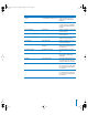
LL1608.book Page 8 Tuesday, February 17, 2004 11:44 AM Command Test Description CPU.G5 CPUID EEPROM checksum verify Verifies both the upper and lower portions of the CPU ID EEPROM CPU.G5 CPU slot number verify Verifies that the CPU slot number in the CPU ID EEPROM matches the physical MLB slot number PCI.OHCIFireWire Register test Performs “walking 1s” test across selected registers PCI.OHCIFireWire Set/clear register test Performs set/clear test across selected registers PCI.
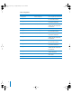
LL1608.book Page 9 Tuesday, February 17, 2004 11:44 AM Mass storage tests 9 Command Test Description Storage.Fixed Device simple test Runs a simple test on the device Storage.Fixed PIO read single block Reads using PIO the first block for 1 block on the device Storage.Fixed PIO read many blocks Reads using PIO starting at the first block for 100 blocks Storage.Fixed PIO 4-corner read test Reads using PIO at the start, middle, and end of the device for 100 blocks Storage.
LL1608.
LL1608.book Page 11 Tuesday, February 17, 2004 11:44 AM Display Tests Command Test Description PCI.ATI Frame buffer address as data test Tests the frame buffer using address as data and !address (the inverse) as data PCI.ATI Frame buffer patterns test Tests the frame buffer using different data patterns PCI.ATI Frame buffer marching 1s and 0s test Tests the frame buffer using marching 1s and 0s PCI.