Xserve AppleCare Service Parts Kit Includes instructions for installing the Xserve components in this kit
1 Contents 5 5 6 7 7 8 9 12 25 25 25 Installing Xserve Service Parts Before You Begin Removing the Xserve from a Rack Opening the Xserve Xserve at a Glance—Internal Components Replacing a Power Supply Replacing the Fan Array Replacing the Main Logic Board Using the Updated Server Serial Number Testing the Xserve Getting More Parts for the Kit 27 Regulatory Compliance Information 3
1 Installing Xserve Service Parts The instructions in this guide show you how to replace the power supplies, fan array, or main logic board in an Xserve with a component from the service parts kit. Before You Begin Review these guidelines before you work inside the Xserve. Working Safely Inside the Xserve Always touch the Xserve chassis to discharge static electricity before you touch any components inside the Xserve.
Removing the Xserve from a Rack To remove the Xserve from a rack: 1 Shut down the Xserve and wait a few minutes to let the internal components cool. WARNING: Always shut down the Xserve and unplug the power cords before opening it to avoid damaging its internal components or the components you are installing. Don’t open the Xserve or try to install items inside it while it is turned on. Even after you shut down the Xserve, its internal components can be very hot. Let it cool before you open it.
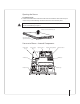
Opening the Xserve To open the Xserve: m Loosen the thumbscrews at the back of the cover and slide the cover back and up to remove it. If you have difficulty, check the enclosure lock on the front panel. WARNING: Even after you shut down the Xserve, its internal components can be very hot. Let it cool before you open it. Slide the cover back and lift it off. Unscrew the two captive thumbscrews.
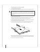
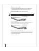
Replacing a Power Supply You can replace a power supply without opening the Xserve or removing it from the rack. If the Xserve has two power supplies, they are hot-swappable; the Xserve continues to operate using only one supply while the second is removed. To remove a power supply: 1 Unplug the power cord from the power supply you are replacing. 2 Pull the handle on the power supply to release it and slide it out of the bay. WARNING: The power supplies in a running Xserve might be hot.
Replacing the Fan Array Be sure to read the guidelines in “Working Safely Inside the Xserve” on page 5 before you start this procedure. To remove the fan array: 1 Shut down the Xserve, unplug it, remove it from the rack, and wait a few minutes to let the Xserve internal components cool. For instructions, see page 6. It’s a good idea to use the enclosure key to lock the enclosure lock on the front panel so you don’t inadvertently unlatch a drive module while you’re moving the Xserve.
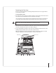
4 Use a medium Phillips screwdriver to loosen the thumbscrews at the ends of the fan array and lift the array out. Use a screwdriver to loosen the two thumbscrews and lift the fan array out. Now you’re ready to install the replacement fan array. To install the fan array: 1 Align the power connector on the array with its counterpart on the power distribution board and lower the array into the chassis. Be sure the power connector is fully seated.
3 Install the airflow duct and fasten the five screws that hold it in place. Airflow duct Captive screws Note: Be sure you route the backplane cable and the front panel cable through the channel on the underside of the duct, as shown in the illustration. Backplane cable Front panel cable Support on airflow duct Power supply Tab on airflow duct 4 Slide the Xserve top cover into place and tighten the two thumbscrews at the back. 5 Lock the enclosure and return the Xserve to the rack.
Replacing the Main Logic Board Be sure to read the guidelines in “Working Safely Inside the Xserve” on page 5 before you start this procedure. To remove the main logic board: 1 Shut down the Xserve, remove it from the rack, and wait a few minutes to let the Xserve internal components cool. For instructions, see page 6. WARNING: Wait a few minutes for the Xserve to cool down before you try to replace the main logic board. Components on and near the board may be very hot.
7 If the system includes a built-in graphics card, remove the four screws that secure the card to the main logic board and remove the graphics card. Optional graphics card 8 Disconnect both ends of the backplane cable and remove it. Then disconnect the ends of the optical drive cable and front panel cables where they connect to the main logic board. Lay the loose ends out of the way.
9 Remove the processor heat sinks. Important: Each heat sink is connected to the main logic board by small temperature sensor wires. Be careful not to pull on the wires as you lift the heat sink enough to disconnect the wires from the main logic board. It’s easier to reach the wire connectors if you start with the heat sink closest to the DIMM slots. a Loosen the four screws securing the heat sink that is closest to the DIMM slots.
10 Remove the processors. Important: Handle the processors carefully. Hold the processors by the edges only and be careful not to touch the gold contacts on the bottom of the processor or smear the old thermal grease. a Unclip the processor retainer spring. b Lift the tab on the hinged retainer to open it. Unclip the retainer spring, open the hinged retainer, and carefully remove the processor.
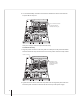
11 Loosen the single thumbscrew on the power distribution board and pull up on the screw until it pops up. Then slide the board away from the main logic board until it is disconnected. Don’t remove the power distribution board, but make sure its edge connector tabs are all the way out of the connector on the main logic board.
12 Remove the main logic board. a Loosen the nine thumbscrews holding the board in place. Pull up on each loosened screw until it pops up. Loosen the nine thumbscrews on the main logic board. b Lift the front edge of the board first, pull the board forward until the connectors are clear of the back panel, and then remove the board. Lift the main logic board out of the Xserve. You’re now ready to install the new main logic board.
To install the main logic board: 1 Guide the new main logic board into place and secure it. a With the front edge of the board raised 1–2 inches (3–5 cm), guide the system identifier button and the connectors on the back edge of the board into the openings in the back panel, and then lower the front edge of the board into place. Important: Don’t bend or flex the main logic board. Make sure the system identifier button extends cleanly through its opening and operates freely.
2 Slide the power distribution board back into place and tighten the thumbscrew. Make sure the tabs on the power distribution board go completely into the connector on the main logic board. If the board doesn’t slide easily, make sure the thumbscrew is popped up so it doesn’t catch on the mounting post beneath the board.
4 Install the processors. Important: If you haven’t removed all old thermal grease from the processors, return to step 3. Don’t try to remove the grease with the processor installed on the main logic board. a Unsnap the protective plastic cover from the processor retainer on the new main logic board, unclip the processor retainer spring, and open the hinged retainer.
5 Apply new thermal grease and install the heat sinks, starting with the processor nearest the power supply bays. a Evenly apply the entire contents of one grease syringe (provided in the kit) to the raised top surface of the processor. Be careful not to spread grease on the retainer. Cover the top, metallic surface of the processor evenly with thermal grease. Use the entire contents of one syringe for each processor. Do not apply thermal grease to the processor retainer.
6 Reconnect the front panel cable, the optical drive cable, and the backplane cable. Backplane cable Optical drive cable Front panel cable 7 If you have a built-in graphics card, fasten it to the main logic board. Guide the mini-DVI connector on the back edge of the card through the opening in the back panel of the Xserve. Then position the mounting holes in the card directly over the posts on the main logic board and secure the card with four screws.
8 Remove the plastic tab separating the battery from the contact on the battery holder. Battery 9 Install the PCI risers and cards (or blanks). a Align the riser with the slot and press to seat it. b Tighten the captive screws that secure the riser bracket to the back panel. Captive screws Captive screws c Repeat this process to install the second riser and card (or the blank, if there is no riser).
10 Install the fan array and airflow duct. For instructions, see page 10. 11 Install the DIMMs. Important: Be sure to return each DIMM to the same slot you removed it from. 12 Remove the Ethernet MAC address labels that are taped to the middle of the new main logic board. Peel each label off the backing and place it over the old address on the system information tag. Labels taped to logic board System information tag 13 Replace the power supplies. For instructions, see page 8.
Using the Updated Server Serial Number When you use Server Assistant to install Mac OS X Server on an Xserve remotely, you need to enter a password consisting of the first eight digits of the Xserve hardware serial number. After you replace the main logic board, the original serial number is no longer valid. Instead, use the serial number 12345678.
Regulatory Compliance Information Disposal and Recycling Information Dispose of your Xserve and its battery according to your local environmental laws and guidelines. For information about Apple’s recycling program, go to www.apple.com/environment. European Union The symbol above means that according to local laws and regulations your product should be disposed of separately from household waste. When this product reaches its end of life, take it to a collection point designated by local authorities.
www.apple.