Xserve RAID User’s Guide Includes hardware setup and expansion, basics of using RAID, and important safety information for Xserve RAID systems
K Apple Computer, Inc. © 2003 Apple Computer, Inc. All rights reserved. Under the copyright laws, this manual may not be copied, in whole or in part, without the written consent of Apple. Your rights to the software are governed by the accompanying software license agreement. The Apple logo is a trademark of Apple Computer, Inc., registered in the U.S. and other countries.
Contents Preface About This Guide 1 7 Introducing Xserve RAID 9 Unpacking the System 10 Your System at a Glance—Front Panel 12 Your System at a Glance—Back Panel 14 Your System at a Glance—Mounting Hardware 2 16 Preparing to Install Xserve RAID in a Rack 19 Guidelines for Installation 19 Precautions for Handling the System 19 Choosing the System’s Location in the Rack Rack Stability 21 Electrical Power 21 Operating Environment 22 Security 22 20 3
3 Mounting Xserve RAID in a Rack 23 Getting Ready to Install the System 24 Determine the Position for the System in the Rack Prepare the System for Installation 26 Installing the System 26 Assemble the Brackets and Extenders 27 Mount the System in the Rack 34 Secure the System in the Rack or Cabinet 35 Moving the Xserve RAID System 36 4 25 Connecting Xserve RAID to a Host System and a Network Installing the Host Bus Adapter Card in the Host System 38 Connecting Xserve RAID to a Host System or Switch 3
7 RAID Overview 57 Setting Up the Xserve RAID System 57 Installing Xserve RAID Hardware and Software About RAID Storage 58 How RAID Works 58 Data Storage Methods 59 RAID Levels 60 Hardware and Software RAID 61 What’s Next? 62 8 Planning RAID Storage for the Xserve RAID System 57 63 Tools for Configuring the Xserve RAID System 63 RAID Controllers and Drive Modules 64 Xserve RAID Schemes 66 A System With Four Drive Modules 66 A System With Seven Drive Modules 70 A System With 14 Drive Modules 73 Storag
Glossary 81 Appendix A Specifications 83 RAID Controller Specifications 83 Fibre Channel PCI Card Specifications 83 Apple Drive Module Specifications 84 Dimensions and Operating Environment 84 Ethernet Specifications 84 UPS Interface Specifications 84 Power Supply Specifications 86 Cooling Module Specifications 86 Battery Module (Optional) Information 86 Appendix B Safety, Maintenance, and Ergonomics Important Safety Information 87 Handling Your System 88 Power Supply 88 Cleaning Your Equipment 88 Appl
P R E F A C E About This Guide Congratulations on purchasing Xserve RAID, a breakthrough storage solution that delivers superior capacity, performance, and data protection. This guide contains instructions for installing the Xserve RAID system in a rack and exchanging components, as well as an introduction to RAID (redundant array of independent disks) technology and a guide to planning storage with your Xserve RAID system.
C H A P T E R 1 1 Introducing Xserve RAID Your new Xserve RAID storage system provides high availability and scalable capacity and performance. Key features of Xserve RAID include m 3U enclosure (5.
Unpacking the System The Xserve RAID system is shipped in special packaging to facilitate simple and safe removal from the carton. As noted previously, always work with a second person to lift or move the system. Follow the steps below to open the carton and remove the system from its packaging. 1 Locate a sturdy table, cart, or other flat surface on which to place the system. The destination surface should be as close as possible to the system’s carton.
5 Remove the protective foam and the two boxes on top of the system. 6 Fold back the plastic covering on the unit and fold down the carton at the front and back of the system. 7 With one person at the front of the system and one at the back, carefully slide your hands between the system and its plastic cover where there are openings in the supporting foam, lift the system out of the carton, and put it on the table or other surface. The unit is heavy. You must have two people lift it out of the box.
Your System at a Glance—Front Panel Drive module lock and status light Power supply status light 12 Chapter 1 System identifier button and light Cooling system status light Mute button Temperature status light Host activity lights Controller status light Drive module activity and status lights Fibre channel link lights Drive modules
Drive module lock and lock status light The lock secures the drive modules in the system. It can be locked and unlocked with the enclosure key supplied with the system (or a 3 mm. hex key). System identifier button and light The system identifier light turns on if a problem is detected. You can also turn it on manually by pressing the button. This indicator is useful for locating a particular unit in a rack with multiple systems. A duplicate is on the back panel.
Your System at a Glance—Back Panel System identifier button and light Mute button Controller status light RAID controller reset button Cooling module status light Power button and light Optional battery module bay (2) Ethernet port and status light (2) Power supply status lights Power supply (2) Fibre channel port and status light (2) Power socket (2) RAID controller module and status light (2) 14 Chapter 1 Cooling module (2) UPS interface port (2)
System identifier button and light The system identifier light turns on if a problem is detected. You can also turn it on manually by pressing the button. This indicator is useful for locating a particular unit in a rack with multiple systems. A duplicate system identifier button and light are on the front panel. (See “Using Status Lights and Other Indicators” on page 46 for more information.) — Mute button Press to turn off the audible alarm that signals an error condition.
Your System at a Glance—Mounting Hardware C A2 E A1 Front mounting screws (2) D Rear securing screws (2) Long screws (8 + extras) (10-32 x 3/4") B Long screws (8 + extras) (M6 x 20mm) Mounting template Shoulder bolts (6 + extras) (M5 x 14mm) Cage nuts + extras (if needed) (M6) 16 Chapter 1 Short screws (6 + extras) (M5 x 6mm) Washers (6 + extras) (M5 x 1mm) Hex key wrench (5mm) Nuts (6 + extras) (M5 x 4mm) Enclosure key (for security lock on front panel)
L-shaped brackets (A1 and A2) Two large L-shaped brackets attach to the front of the four-post rack and support the system. Bracket extenders for a 24- to 29-inch rack (B) These extenders attach to the brackets A1 and A2 and to the rear rail of the standard fourpost rack. Bracket extenders for a 29- to 36-inch rack (C and D) Connect these two extenders and attach them to the brackets A1 and A2 and to the rear rail of the deep four-post rack.
C H A P T E R 2 2 Preparing to Install Xserve RAID in a Rack Before you install the system in a rack, carefully consider the placement of the unit in its rack and several other factors in the infrastructure that will keep the system operating efficiently.
m Lift with a smooth motion; don’t jerk the load up or down. m Keep the system close to your body and at waist level to lessen the load on your back. m Maintain body alignment while lifting, so that your back, ears, shoulders, and hips are in line and your eyes and feet are facing the system. m To turn while holding the system, use your feet; don’t twist your back or torso. Choosing the System’s Location in the Rack The Xserve RAID system is designed for use in a four-post rack or cabinet.
m For a rack that has multiple devices, you may want to prepare a list of all equipment in the rack and the requirements for each unit. Such a list should include the following information: Component Power needed Clear area front / back Height in rack Temperature range Other Xserve RAID Server 1 Server 2 Managing Cables Your Xserve RAID system uses three to six cables and two power cords.
m If there are devices in the system’s location that use large amounts of power, use surge protectors or power conditions as part of the installation. When planning for electrical power, make sure you have more power than the total power requirements specified for all components. Also make certain that the power load is distributed evenly among circuits to the rack’s location. Consult an electrician or other expert if you need assistance with planning for the power needs of your components.
C H A P T E R 3 3 Mounting Xserve RAID in a Rack The Xserve RAID system is specifically designed for rack mounting. It is not designed for use as a desktop system. You can install the system in a four-post cabinet or rack that is 19 inches wide and between 24 and 36 inches deep. The system is 5.25 inches (3U) high.
The brackets and screws necessary to attach the system to a four-post rack with threaded holes are included with your system. If your rack has square, unthreaded holes, you may need to insert cage nuts (some are provided with the system) into the appropriate holes before attaching the system to the rack. Some racks have pre-threaded holes. Other racks use various types of removable cage nuts to secure equipment.
Note: Several sets of screws are provided with the system. These screws are designed for racks with prethreaded holes. Check the documentation for your rack and use the appropriate set of screws; most racks use one of the sizes. If screws are provided with your rack, you can use those as well. m To measure and mark the position of the system in the rack, you can use the metal mounting template that came with the system.
m If your rack is 29 to 36 inches deep, combine the shorter extender with a three-hole lip at the one end (item C in the illustration below) and the longest piece (with no lip; item D in the illustration), using the solid bar (item E in the illustration). This combination creates an extender long enough to reach the rear of a deep rack.
Assemble the Brackets and Extenders Follow these steps to assemble the brackets and extenders for the depth of your rack.
4 Fit the assembled pieces into the rack so that the extender’s lip is near the rear rail and the lip of bracket A points toward the outer edge of the rack at the front rail. Adjust the mounting bracket assemblies to fit the rack. The flanges at both ends should be on the outside of the rack posts. The orientation of bracket A determines on which side of the rack it belongs. The lower part of this L-shaped bracket faces inward (to support the system).
7 Securely fasten two long screws in the top and bottom holes of bracket A on each of the rack’s front rails. 8 With one person on each side of the rack, slide the extender backward until its lip is even with the rear rail of the rack. 9 At the back of the rack, use two long screws to secure the extender to the rear rail. Put the screws in the top and bottom holes in the extender.
For a Rack 29 to 36 Inches Deep 1 Gather the two brackets (A1 and A2), the two shorter extenders (item C in the illustration below), the two flat pieces (item D in the illustration), the two solid bars (item E in the illustration), and the necessary screws and nuts: m six short screws for assembling two brackets and extenders m six shoulder bolts, six washers, and six nuts for joining the brackets and extenders m four long screws for securing the brackets to the rack m two mounting screws for attaching th
2 Join the shorter extender (C) and the flat piece (D) by placing the solid bar (E) between them as shown in the illustration below. C D Pass three of the shoulder bolts through the slot in part D, then through the holes in part E, and finally, through the slot in part C. Secure each bolt with a washer and then a nut. Tighten them securely. E Pass three of the short screws through the holes in part D and attach them to part A1 or A2. Tighten them securely.
5 Fit the assembled pieces into the rack so that the extender’s lip is near the rear rail and the lip of bracket A points toward the outer edge of the rack at the front rail. Adjust the mounting bracket assemblies to fit the rack. The flanges at both ends should be on the outside of the rack posts. The orientation of bracket A determines on which side of the rack it belongs. The lower part of this L-shaped bracket faces inward (to support the system).
8 Securely fasten two long screws in the top and bottom holes of bracket A on each of the rack’s front rails. Temporarily place the mounting template over the two posts on parts A1 and A2. Attach each bracket assembly to the front rack post with two of the screws provided. Tighten the screws and then remove the template. 9 10 With one person on each side of the rack, slide the extender backward until its lip is even with the rear rail of the rack.
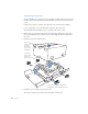
Mount the System in the Rack When the brackets are secured to the rack, you can put the system in the rack. Follow these steps to mount the Xserve RAID system in the rack. 1 With one person on each side of the system, lift it so that the bottom of the unit is level with the lower part of the bracket. 2 Slide the system into the rack. With one person supporting each side of the unit, slide it into the rack. Slide the unit back in the rack until it engages the small posts on the L-brackets.
3 Use the two rack screws to secure the system to the front rail of the rack. Important Be sure to tighten the rack screws so that the system is firmly attached to the rack. You can use the Phillips screwdriver to tighten these screws. Parts of the unit may be covered by clear plastic film that protected it during shipment. Remove the film. Insert and tighten the two mounting screws to secure the unit to the rack.
Once the system is mounted and secured in the rack, you can connect it to a host server or computer. Note: The user-serviceable parts described in this manual can be installed or replaced while the system is mounted in the rack. See Chapter 6, “Installing or Replacing Components,” on page 49 for details. Moving the Xserve RAID System If you need to move the system after you have mounted it in a rack or cabinet, you must follow the precautions listed below.
C H A P T E R 4 4 Connecting Xserve RAID to a Host System and a Network Xserve RAID provides two groups of up to seven drive modules, each with a dedicated RAID controller. This flexible design allows you to connect the storage system to a single host using two fibre channel cables, or to dual hosts using one cable to each host. To establish communication with a host, you can purchase the Apple Fibre Channel PCI Card or use a compatible fibre channel card that supports the Xserve RAID system.
Installing the Host Bus Adapter Card in the Host System The Apple Fibre Channel PCI Card is a 7-inch PCI card that you can install in the Xserve system or Power Mac G4 models with a processor speed of 800 MHz or faster. This adapter card has two fibre channel connectors, which you use to connect the card to the Xserve RAID system. Consult the documentation that came with your server or computer for instructions on installing the adapter card.
Connecting the System to Xserve or a Power Mac G4 The fibre channel cables supplied with the Apple Fibre Channel PCI Card have different connectors—an SFP connector and an HSSDC2 connector—at each end, as shown in the illustration below. Latch release SFP connector HSSDC2 connector Follow these steps to connect the system to Xserve or a Power Mac G4. 1 If necessary, install the adapter card in the server or computer.
3 Connect the HSSDC2 connector at the other end of each cable to the connector on each of the RAID controllers in the Xserve RAID system. The latch on the cable’s connector should be at the top as you insert it. HSSDC2 ports Connecting Xserve RAID to a Switch or Hub You can connect the system to a switch or hub that has fibre channel ports. (See “Xserve RAID Hardware Connections” on page 79 for an example of this type of connection.
If the switch or hub doesn’t accept an SFP connector, use a fibre channel cable with a connector that is compatible with it. Latch release SFP connector 3 HSSDC2 connector Connect the HSSDC2 connectors on the cables to the RAID controllers on the Xserve RAID system. The latch on the cable’s connector should be at the top as you insert it into the controller.
Connecting to a Network To allow remote setup and management of Xserve RAID, you need to make a standard Ethernet connection to a network hub or server. You use this connection to configure your RAID storage system and to administer the system with the software tools provided with it. See the document “Using RAID Admin and Disk Utility” on the CD that came with your system for details on using the management software.
Connecting Power to the System The final step in preparing the system is connecting a power cord to each power supply on the back panel of Xserve RAID. Follow these steps to connect the two power cords. 1 Lift the small support clip on the system’s back panel, then connect one of the power cords to the socket at the lower right of one power supply. Note: Be sure to use the power cords supplied with the system to ensure that the clip holds them securely and avoids accidental removal of a cord.
Connecting an Uninterruptible Power Supply To protect the system’s operation during an interruption in power, you may want to install an uninterruptible power supply (UPS) in or near the rack that holds your Xserve RAID system. The UPS unit must have a serial interface that supports the basic signaling protocol. You can obtain a UPS unit through the Apple online store at www.apple.com. Follow these steps to connect a UPS unit to the system.
C H A P T E R 5 5 Using the Xserve RAID System After you’ve connected to the host system or switch, you can turn on Xserve RAID and use the RAID Admin software to configure it. Starting Up the System When you plug the power cords into Xserve RAID, the system begins its internal diagnostics. During this time (about 30 seconds), you cannot use the power button to turn on the system. Power button When the diagnostics are complete, the small light next to the power button blinks.
Turning Off the System You can shut down the Xserve RAID system using the admin software or the power button on the system’s back panel. Both methods are designed to avoid data loss. Do not pull out the power cords to turn off the system. Important Before shutting down, be sure you have unmounted the drives from your OS. Shutting Down From a Remote System Using Software From the host system or a remote computer, use the RAID Admin application to shut down the system.
Icon — Indicator Color Description System identifier Yellow (solid or blinking) Indicates a hardware error in the system or that someone has turned on the light manually; check the monitoring software for more information.
The system’s two power supplies each have three LEDs that indicate status. These indicators are listed in the table below.
C H A P T E R 6 6 Installing or Replacing Components Your Xserve RAID system is designed so that you can install or exchange drive modules, power supplies, and cooling modules while the system is operating. All of these components, as well as the RAID controller modules and optional battery modules, are designed as fieldreplaceable units. About Replacing Components To maintain proper airflow within the Xserve RAID system, follow these guidelines for removing or replacing components.
2 Remove the blank drive module or the drive currently installed. m If there is no drive installed, press the handle of the blank drive module so that it pops out, then pull the blank drive module out of the front panel. Security lock Press the handle on the blank drive module until the handle pops out and then pull the module out. m If there is a drive module already in the bay: a Make sure the drive currently in the bay is not part of a RAID set, or you could lose data.
4 If the handle is not flush with the front of the system, gently press it. If it still is not flush, pull the module out and reseat it. The drive isn’t fully seated until the handle is flush with the front of the system. The disk status light turns green to indicate normal operation. Be sure to save the blank drive module if you removed one. A blank module should always be placed in an empty drive bay to maintain proper airflow through the system.
5 Hold the new power supply by the handle and carefully slide it into the system until it clicks into place, then push the handle upward and fold it into place at the top of the unit. Slide the power supply into the unit and push the handle up to lock it in place. 6 Attach the power cord to the back of the new power supply and secure the clip that holds the cord in place. 7 Plug the cord into the power source. Note: Keep the packaging and the old power supply.
Follow these steps to replace a cooling module. 1 Press the two latches on the front of the cooling module apart and use them to pull the unit out of the system. If the latches have small tabs on the inside surface, slide those tabs toward you to open the latches fully. Push the two latches on the cooling module outward to release it and then pull the module out of the unit. 2 Remove the packaging from the new cooling module.
Replacing a RAID Controller Module You must shut down the system before removing a RAID controller module (by unmounting all drives on the controller you are not changing, then shutting down and removing the power cords). See the document “Using RAID Admin and Disk Utility” on the CD that came with your system for shutdown instructions. When a controller module is out of the system (or has failed), the drive modules controlled by that card are not active and do not lose data stored on the drives.
3 Push the two latches together to fully seat the module in the system. If the latches have small tabs on the inside, slide the tabs away from you and then close the tabs. Note: Keep the packaging and the old controller module. You will need to return the failed component to Apple when you receive a replacement. Installing or Replacing a Battery Module You can obtain optional battery modules to protect data in the Xserve RAID controllers’ cache in the event of a power interruption.
2 Remove the packaging from the new battery module. Hold the battery module by the handle and carefully slide it into the system until it clicks into place. Push the backup battery into the unit while squeezing the two latches together. Release the latches when the battery is in position to lock the module in place. Be sure to save the battery compartment cover for use when no module is installed. Warning There is risk of explosion if a battery module is replaced by an incorrect type.
C H A P T E R 7 7 RAID Overview Xserve RAID provides a powerful, versatile, and cost-effective answer to the growing storage requirements of graphics and video production companies, email and web services, educational file sharing, and other businesses. You can configure the Xserve RAID system in a variety of ways, using up to 14 drives in two groups of 7 drives. Each group has a separate RAID controller.
m installing the Apple Fibre Channel PCI Card in a host system and connecting it to the Xserve RAID system using fibre channel cables m connecting to an Ethernet network You use the RAID Admin software to configure RAID storage on your system. Use the Xserve RAID CD, supplied with the system, to install RAID Admin on any computer or server that you want to use for remote administration of the system. See the document “Using RAID Admin and Disk Utility” on the CD that came with your system for details.
Once you have defined a group of drive modules as a RAID set, the controller groups those drives into “logical disks.” On the Xserve RAID system, each logical disk appears to the host system and the RAID Admin software as one disk, regardless of the number of actual drives in that logical unit. See “Xserve RAID Schemes” on page 66 for examples of RAID sets you can configure on the Xserve RAID system. Each controller in the Xserve RAID system can have a maximum of three logical disks.
RAID Levels The Xserve RAID system supports several RAID levels. Each level has a different architecture and provides varying degrees of performance and fault tolerance. Each level has characteristics to achieve maximum performance or redundancy depending on the data environment. Understanding the differences among RAID levels will help you set up your Xserve RAID system to best meet your data performance and security needs.
RAID 3: Parallel transfer with parity on dedicated disk RAID level 3 adds redundant information to a striped set of drives with parallel access, allowing regeneration and reconstruction in the event of a disk failure. The parity data is stored on one disk dedicated to this purpose. RAID 3 provides high transfer rates and high reliability and availability, at a lower cost than RAID levels that incorporate mirroring. RAID 3 requires a minimum of three drives.
RAID 30 RAID level 30 essentially combines RAID 3’s dedicated parity (reliability) and RAID 0’s striping (performance). RAID 30 requires at least six drives. This level provides high reliability; one drive in each data pair could fail and data would still be available. To create a RAID 30 configuration, you use RAID Admin and Disk Utility. See the document “Using RAID Admin and Disk Utility” on the CD that came with your system for instructions.
C H A P T E R 8 8 Planning RAID Storage for the Xserve RAID System Before you use the RAID Admin and Disk Utility software to set up your RAID storage, it’s a good idea to become familiar with the variety of configurations, or schemes, available for the Xserve RAID system. This chapter describes these schemes and illustrates how each RAID level is applied to a set of drives.
RAID Controllers and Drive Modules The Xserve RAID system has two RAID controllers, each of which controls the drive modules on one side of the system. The drive modules are numbered 1 to 7 on the left side of the system and 8 to 14 on the right side (when viewing the system from the front).
The illustration below provides a graphic representation of all this information.
Xserve RAID Schemes A RAID scheme refers to how the storage device’s RAID sets are configured with different RAID levels. You can configure the Xserve RAID system with a variety of storage schemes. The illustrations show examples of the three standard versions of Xserve RAID hardware— 4 drive modules, 7 drive modules, and 14 drive modules. An additional illustration shows examples of Xserve RAID systems connected to a host system or fibre channel switch.
RAID 1 Schemes You can use RAID 1 several ways on a four-drive system, depending on how you divide the drive modules between the RAID controllers and how you mirror the data on the drives. If all the modules are on one controller, you can have two RAID sets on one controller. RAID 1 Appears as Disk 1 Mirror Mirror Disk 2 If two modules are on each controller, you can create one RAID set on each side.
You can use RAID 3 or 5 with four drive modules only on one Xserve RAID controller.
RAID 0+1 and RAID 10 Schemes On the Xserve RAID system, RAID 0+1 is a stripe of mirrored pairs. An example of this configuration is shown at the top of the illustration below. Using a combination of the hardware controller and software, you configure the system using RAID 10 with two drive modules on each controller. The drive modules on each side can be either striped together or mirrored.
A System With Seven Drive Modules You can use the following RAID levels on an Xserve RAID system with seven drive modules: m RAID 0 m RAID 1 m RAID 3 m RAID 5 m RAID 30 m RAID 50 Note: This list is representative but does not include all possible schemes. RAID 0 Schemes You can use RAID 0 several ways, depending on how you divide the drive modules across the RAID controllers. If all of the modules are on one RAID controller, all drives can be striped together.
RAID 1 Schemes You can use RAID 1 several ways, depending on how you divide the drive modules between the RAID controllers, how you choose to mirror the drives, and where you put the module you use as a hot spare. The hot spare is a drive that the RAID controller automatically uses to rebuild data if another drive fails. The hot spare is only available to mirrored pairs on the same controller.
RAID 3 and 5 Schemes You can use RAID 3 or 5 with or without a drive module designated as a hot spare. You can use RAID 3 or 5 with four drive modules on one controller and three on the other or with all the modules on one RAID controller. If a hot spare is used, it serves all arrays on the controller where the spare is located.
A System With 14 Drive Modules On a system with 14 drive modules, you can use these RAID levels. m RAID 0 m RAID 00 m RAID 1 m RAID 10 m RAID 0+1 m RAID 3 m RAID 5 m RAID 30 m RAID 50 Note: This list is representative but does not include all possible schemes. RAID 0 and RAID 00 Schemes With seven drive modules on each controller, you can stripe each side into a RAID set. RAID 0 Appears as Stripe Disk 1 Stripe Disk 2 Using software RAID (Disk Utility), you can stripe the two RAID sets together.
RAID 0+1 and RAID 10 Schemes With seven drive modules on each controller, you can create 0+1 configurations with a hot spare on each controller or you can use Disk Utility to mirror the two sides in a RAID 10 configuration. RAID 0+1 Appears as RAID 0 +1 RAID 0 +1 Hot spare Disk 1 Hot spare RAID 10 (alternate configuration) Appears as Stripe Stripe Use software RAID to mirror two RAID sets.
RAID 3 and 5 Schemes You can use RAID 3 or 5 with or without a drive module designated as a hot spare on each controller, or you can create four RAID sets and use Disk Utility to stripe or mirror the sets on the same or separate controllers.
You can also set up three mirrored pairs and one hot spare with RAID 1 on one controller, and stripe all the drives together on the other controller using RAID 0, 3, or 5. (The spare is only for the drives on the controller where the spare is located.
RAID 30 and 50 Schemes You can configure two RAID 5 sets using the RAID controller and then use software (Disk Utility) to stripe those two sets. RAID 30 or 50 Appears as RAID 3 or 5 Disk 1 RAID 3 or 5 Use software RAID to stripe two RAID 3 or 5 sets, which appear as one maximum capacity RAID set. RAID 30 or 50 Appears as RAID 3 or 5 RAID 3 or 5 RAID 3 or 5 RAID 3 or 5 Disk 1 You can use software RAID to stripe like pairs on the same or separate controllers.
Storage Capacities for Xserve RAID Schemes 78 Chapter 8 RAID Level Capacity RAID 0 Total of all drives RAID 1 Total of one drive RAID 0+1 One-half the total capacity of all drives (sum of RAID 1 member sets) RAID 3 Total of all drives minus one drive (parity disk) RAID 5 Total of all drives minus one drive (distributed parity) RAID 10 One-half the total of all drives RAID 30 Total of all drives minus two drives RAID 50 Total of all drives minus two drives
Xserve RAID Hardware Connections The Xserve RAID system offers three standard hardware configurations—a system with 4 Apple drive modules, 7 drive modules, or 14 drive modules. You can connect any of these systems to a host or fibre channel switch in several ways. The examples below show several of the possible connections.
Connecting a Four-Drive System to a Host Computer or Switch You can connect your Xserve RAID to a host computer using one fibre channel cable if your drive modules are on one RAID controller. If your drive modules are spread across both RAID controllers, two on each controller, connect both controllers to the host computer using two fibre channel cables.
Glossary Common RAID Terms A grouping of disk drives; also known as a set. Any number of drives can be configured together to form a RAID array. The same RAID level is applied to all drives in an array. Array: Hot spare: A feature of the RAID controller that detects a drive failure and automatically uses an available drive to rebuild the data from the failed drive. (Not all RAID sets include a hot spare.) A storage method in which the same data is stored twice on two or more different drives.
A P P E N D I X A A Specifications RAID Controller Specifications m 2 gigabit-per-second (Gb/sec.) fibre channel port m Seven independent ATA-100 drive channels m Minimum 128 megabytes (MB) of PC-100 SO-DIMM RAM m Two 66 megahertz (MHz) PCI buses m Hardware parity generation m Support for RAID 0, 1, 3, 5, 0+1 m RAID Now (RAID creation during initialization) m Variable rebuild rate m Tag command queueing m Hot sparing Fibre Channel PCI Card Specifications m 2 Gb/sec.
Apple Drive Module Specifications m ATA-100 m Hot-swappable modules (compatible with Xserve) m Temperature sensor m SMART drive support Dimensions and Operating Environment Dimensions m m m m m Height: 133 mm (5.25 in.) (3U) Width: 483 mm (19.0 in.) with mounting brackets Depth: 442 mm (17.4 in.) Drive module weight: 2 lbs. (0.9 kg) Weight: 60–100 lbs. (27–45 kg), depending on configuration Weight depends on the number of drive modules installed in the system.
m 9-pin D connector 1 2 3 4 5 6 7 8 9 m Pin signals 1: (CD) UPS battery low (20%) 2: Not used 3: Not used 4: (DTR) handshake option 5: Ground 6: Not used 7: (RTS) reserved 8: (CTS) Line fail—switch to UPS battery 9: (RI) reserved m Serial cable to UPS should be number 940-0020B (or comparable cable) for APC basic signaling Specifications 85
Power Supply Specifications AC line input m 450 watt ( W ) total power capacity for each power supply (system uses a maximum of 450 W total) m 100–127/200–240 volts ( V ) AC; 7.6/3.
A P P E N D I X B B Safety, Maintenance, and Ergonomics Important Safety Information For your own safety and that of your equipment, always take the following precautions. The only way to disconnect power completely is to unplug the two power cords. Make sure at least one end of each power cord is within easy reach so that you can unplug the Xserve RAID when you need to.
Handling Your System Follow these guidelines for handling your Xserve RAID system and its components: m When lifting or moving the system, always have two people carry it and place the unit on a sturdy, flat surface. Do not attempt to lift or move the system by yourself. The weight of the unit requires two people to lift and support it. Important m When connecting or disconnecting a cable, always hold the cable by its connector (the plug, not the cord).
m Use a damp, soft, lint-free cloth to clean the exterior. Avoid getting moisture in any openings. m Don’t use aerosol sprays, solvents, or abrasives. m To clean the case, shut down the system completely and then disconnect the power plugs. (Pull the plug, not the cord.) Apple and the Environment Apple recognizes its responsibility to minimize the environmental impacts of its operations and products. For more information, go to www.apple.com/about/environment.
Communications Regulation Information FCC Statement This equipment has been tested and found to comply with the limits for a Class A digital device, pursuant to Part 15 of FCC rules. These limits are designed to provide reasonable protection against harmful interference when the equipment is operated in a commercial environment.