Xserve User’s Guide Includes setup, expansion, and hardware specifications for Xserve
K Apple Computer, Inc. © 2003 Apple Computer, Inc. All rights reserved. Under the copyright laws, this manual may not be copied, in whole or in part, without the written consent of Apple. Your rights to the software are governed by the accompanying software license agreement. The Apple logo is a trademark of Apple Computer, Inc., registered in the U.S. and other countries.
Contents Preface Introducing Xserve 1 Xserve Overview 7 9 Your Server at a Glance—Front Panel 10 Your Server at a Glance—Back Panel 12 Your Server at a Glance—Interior 14 Your Server at a Glance—Mounting Hardware 2 Preparing to Install Your Server Guidelines for Server Installation 19 Choose the Server’s Position in a Rack Electrical Power 20 Operating Environment 21 Rack Stability 21 Considerations for Cables 21 Security 22 3 Installing Your Server in a Rack 16 19 19 23 Getting Ready to Install 2
Installing the Server in a Two-Post (Telco) Rack 47 Connect Cables Directly to the Server 50 Disconnecting Cables From the Server’s Back Panel 51 Preparing the Server for Software Setup 51 4 Using Your Server 53 Starting Up the Server 53 Monitoring Status Lights and Other Indicators on the Server If the Server Has a Problem 55 What to Do If . . .
Appendix B Safety, Maintenance, and Ergonomics Important Safety Information 83 Handling Your Computer Equipment 84 Protecting Your Optical Drive 85 Power Supply 85 Cleaning Your Equipment 85 Cleaning the Server’s Case 85 Apple and the Environment 86 For More Information 86 Health-Related Information About Computer Use 83 86 Contents 5
P R E F A C E Introducing Xserve Congratulations on purchasing your new server. This product is designed to be mounted in a rack. Once the server is installed in the rack, an administrator or other user can slide it open from the front to exchange or add components.
Among the services included with the Mac OS X Server standard configuration are m file and print services for Macintosh, Windows, and UNIX clients m high-performance Apache web server, with integrated WebDAV and SSL m World Wide Web application deployment platform m QuickTime Streaming Server m IP filtering, DHCP, DNS, and SLP networking services m directory services m mail service m NetBoot server for Macintosh client computers that can start up from a server m tools for remote server configuration and mon
C H A P T E R 1 1 Xserve Overview The illustrations on the pages that follow provide a reference for the server. Depending on the configuration of your server, it may look slightly different from the illustrations shown here. See Chapter 2, “Preparing to Install Your Server,” on page 19 for suggestions on planning the operating environment for the server and where to mount it in a rack.
Your Server at a Glance—Front Panel FireWire 400 port Ethernet card link light System activity lights Optical drive System identifier button/light Enclosure lock and status light Apple Drive Module bays (4) Power button /light Securing thumbscrews (2) 10 Chapter 1 Built-in Ethernet link light Drive module activity light Drive module status light
® Power button and light Press to turn on the server. Enclosure lock and lock status light The lock secures the enclosure and drive modules in the server. It can be locked and unlocked with the enclosure key supplied with the server. When the enclosure lock is locked (the light is on), the server may not recognize peripheral devices such as a keyboard, mouse, or storage device. Unlock the lock to use those devices.
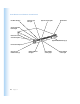
Your Server at a Glance—Back Panel Power socket Gigabit Ethernet port(s) FireWire 800 ports (2) 12 Chapter 1 System identifier button/light USB ports (2) PCI card expansion slots (3) Serial console port VGA monitor port
≤ Power socket The power cord connects here; it is held in place by a special clip so that it stays connected when the server is opened in the rack. System identifier button and light The system identifier light turns on if a problem is detected. It also can be turned on manually by pressing the button. This indicator is useful for locating a particular unit in a rack with multiple servers. A duplicate system identifier button and light are on the front panel.
Your Server at a Glance—Interior Battery PCI/AGP card slot Power supply PCI card slots (2) Chassis release latch RAM slots (4) Chassis release latch Main logic board Blowers 14 Chapter 1
PCI card slots and PCI/AGP card slot You can install PCI expansion cards in the three slots. The two slots on the left side of the server hold 12-inch cards; the slot on the right side holds a 7-inch card, and can also be configured to hold an AGP card, which requires a special adapter. (See “About PCI Cards for the Server” on page 68 for more information about card requirements.) RAM expansion slots You can expand DDR RAM up to 2 GB, using the four slots.
Your Server at a Glance—Mounting Hardware Mounting template Four-post braces Two-post brackets Cage nuts (Metric) Short screws Cage nuts (English) Four-post brackets Short-rack brackets Attachment screws (Metric) 16 Chapter 1 Attachment screws (English) Enclosure key
Four-post brackets Two rivets on each bracket secure it to the brace and the server’s cover. Four-post braces These two long U-shaped pieces support the back of the server and attach it to the rack. Two-post brackets These two short L-shaped brackets attach to the sides of the server’s enclosure and to the rack. Short-rack brackets These two brackets attach the back of the server to a short rack, 24 or 26 inches deep.
C H A P T E R 2 2 Preparing to Install Your Server Before you install the server in a rack, you should carefully consider the placement of the unit in its rack and several factors in the infrastructure that will keep the server operating efficiently.
m The server slides out of the rack from the front. Be sure to leave a minimum of 36 inches clear in front of the server to allow room to open and service it. m To provide access to the server’s back panel and cables, leave at least 24 inches clear behind the server. m If you are installing multiple servers or other components in the rack, place the server so that you can easily open and service it.
m This model is certified only as a component for use with other equipment, where the suitability of the combination has been determined by a Nationally Recognized Testing Laboratory. Operating Environment The operating environment for the server’s rack must meet certain requirements: m Verify that the temperature range of the rack’s location is within the limits established for the server and all other components.
Security Whatever the location of the server and rack, it should be secure. m Make sure that only authorized staff members or technicians can gain access to the rack’s location. m If using a server cabinet that is not in a secure room, be sure that the cabinet is adequately locked and that access to it is limited to authorized staff. m Develop a plan for distributing and controlling keys to the server environment and access codes that allow others to manage servers over the network.
C H A P T E R 3 3 Installing Your Server in a Rack Xserve is specifically designed for rack mounting. It is not designed for use as a desktop system. Warning Do not place a monitor on the server or use the top of the server as a shelf in the rack. Any weight on the server’s enclosure could damage the components inside.
Getting Ready to Install As noted previously, you can install the server in a four-post rack of varying depth or a twopost rack. Instructions for these procedures are given below. Preparations for installing are the same regardless of the type of rack you use. Important Check the documentation for your rack for any special requirements. Before beginning work with the server and rack, make the following preparations.
Some racks have marks at regular intervals (such as 1U) to aid in positioning a server; others may provide a template to help place the server in the rack. If your rack does not have such aids, measure or count holes from an established point. Identify the appropriate holes in all mounting posts before you install the server so that it is mounted level. The distance between holes may vary somewhat on racks made by different manufacturers.
3 Remove the protective faceplate from the server’s front panel by unscrewing the thumbscrews at each side of the faceplate and lifting it off. Set the thumbscrews aside. Remove the two shipping screws. There is one screw on either side of the server. Protective faceplate Remove the four thumbscrews that hold the protective faceplate in place, and remove the faceplate by lifting it straight up. 4 Loosen the two thumbscrews (one on each side) at the front of the server’s enclosure.
5 Remove the cover of the server’s enclosure by sliding it toward the back of the unit. Hold the front thumbscrews to keep the main part of the server in place as you slide the cover toward the back. With the server resting on a flat, clean, and stable surface, slide the cover completely to the rear. Press these two latches to release the cover from the server and remove it.
7 If necessary, install any optional internal components, such as additional memory or a PCI card, in the server. Follow the appropriate instructions in Chapter 5, “Installing or Replacing Server Components,” on page 57. PCI card slots (2) PCI/AGP card slot RAM slots (4) 8 If necessary, install any additional Apple Drive Modules in the front panel of the server. Follow the instructions in “Installing or Replacing an Apple Drive Module” on page 59.
When you’ve installed optional items, you’re ready to connect the server to the rack. If you have a four-post rack or cabinet that is 29–36 inches deep, proceed to “Installing the Server in a Four-Post Rack or Cabinet” on page 29. If you have a short rack that is 24 or 26 inches deep, go to “Installing the Server in a Short Four-Post Rack” on page 42. If you have a twopost rack, go to “Installing the Server in a Two-Post (Telco) Rack” on page 47.
Once you’ve marked the exact position for the server on the rack, you’re ready to attach the server. Here is an overview of the procedure. m Connect the cover of the server to the front of the rack. m Assemble the rear mounting hardware. m Connect the rear mounting hardware to the server enclosure. m Slide the server into the cover and secure it. m Install the cable-management arm. Note: You cannot use the cable-management arm in a short rack, 24 or 26 inches deep.
2 Screw the flanges at the front of the cover to the front posts of the rack. Make sure that the cover of the system is at right angles to both posts. Use the mounting template provided with the system or a right-angle measuring device to determine that the cover is square to the posts on both sides. If the cover is not installed squarely, its shape may change slightly and the cover may not hold the server in the correct position. Important Be careful not to overtighten the flange screws.
3 At the back of the server, position the small bracket inside the server’s cover so that the head of one rivet is facing the side of the cover. Note: Start on the left side of the server (when facing the back). This makes installing the cable-management arm more efficient. 4 Push the rivet head through the hole that’s near the back on the side of the cover. Install the brackets on the inside of the top cover. The forward rivet on each bracket must pass through the hole in the cover.
7 Slide the brace forward or backward so that the flat end of the brace is flush with the back post of the rack, and screw the brace’s flange to the post. Attach the cover to the two rear rack posts using four of the screws provided. 8 Attach the second bracket and brace, as described in steps 3 through 7. Note: If your rack is deeper than the server, the braces and brackets extend beyond the server’s back panel to the rack’s posts.
Place the Server in the Rack Once you’ve attached the cover, you can put the server into the rack. 1 At the front of the rack, lift the server to the level where the enclosure’s cover is installed and slide the server into the cover. Insert the server into the cover and slide it all the way back. 2 Secure the server in the rack by tightening the thumbscrews on the front. Tighten the two thumbscrews to secure the server in the rack.
4 If you’ve installed the server in a cabinet, replace and close the cabinet door. Once the server is secured in the rack or cabinet, you can attach the cable-management arm and cables for the server’s connections. Install the Cable-Management Arm and Cables Xserve has a cable-management arm that allows you to open the server without disconnecting cables. In addition, this device supports the cables and relieves strain on the server’s back-panel connectors.
3 Hold the cable-management arm in the orientation you will use to attach it to the rack or support brace. The short part of the arm should be closer to the server’s back panel and the elongated holes on the long part of the arm should face the left back post of the rack (as you face the back of the server).
Follow these steps to attach the cable-management arm to the rack. 1 At the front of the server, loosen the thumbscrews securing it to the rack and slide the server a few inches forward. Moving the server forward allows you to check the position of the cable-management arm after you mount it. 2 Position the cable-management arm so that the short part is closer to the server’s back panel and the elongated holes on the long part align with the holes on the brace attached to the left post.
6 Connect the cables to the back panel of the server. Power socket Gigabit Ethernet port USB ports (2) 7 FireWire 800 ports (2) Serial console port VGA monitor port Connect the power cord and its retaining clip to the back of the server. If more than one power cord came with your server, use the appropriate cord for the electrical service available at your location. Note: You may need to bend the cord near its plug to fit it into the server. Bending the cord will not affect its operation.
10 After all connections are complete, plug the power cord into a power source. This equipment is intended to be electrically grounded. Your server is equipped with a three-wire grounding plug—a plug that has a third (grounding) pin. This plug fits only a grounded AC outlet. This is a safety feature. If you are unable to insert the plug into the outlet because the outlet is not grounded, contact a licensed electrician to replace the outlet with a properly grounded outlet.
4 Position the cable-management arm so that the hinged section is on the inside of the left brace, about 2 inches behind the server’s back panel. Mount the cable-management arm as close to the back of the server as possible. Rotate the mounting plate on the arm so that it lies against the inside of the U-shaped bracket. The U-shaped bracket should be sandwiched between the arm and the small clamp. Secure the clamp with the screw that held it stored on the arm.
9 Connect the power cord and its retaining clip to the back of the server. If more than one power cord came with your server, use the appropriate cord for the electrical service available at your location. Note: You may need to bend the cord near its plug to fit it into the server. Bending the cord will not affect its operation. Attach the power cord retainer clip to the two loops on the back of the server. Snap the cord into the clip so that it cradles the cord.
Installing the Server in a Short Four-Post Rack Some four-post racks are shorter than the Xserve system. You can install the server in a short rack that is 24 or 26 inches deep using special brackets provided for this purpose. You cannot use the cable-management arm with a short rack. When you install the Xserve system in a short four-post rack, the back of the server extends beyond the rack’s rear posts. Therefore, you cannot install the system in a short enclosed cabinet.
2 Screw the flanges at the front of the cover to the front posts of the rack. Make sure that the cover of the system is at right angles to both posts. Use a right-angle measuring device or object to determine that the cover is square to the posts on both sides. If the cover is not installed squarely, its shape may change slightly and the cover may not hold the server in the correct position. Important Be careful not to overtighten the flange screws. Doing so could change the shape of the cover.
3 Just beyond the rear post of the rack, position the short-rack bracket beside the cover so that the small pin on the bracket fits into the oblong hole closest to the post. The small pin on the bracket faces inward, toward the cover, and it is near the top of the bracket. The L-shaped flange at one end of the bracket faces away from the cover and is close to the rack’s rear post. Note: One of the short-rack brackets is designed for the left side of the cover and the other fits the right side.
5 Slide the bracket toward the rear post until the bracket’s flange aligns with the post, and use two attachment screws to secure the bracket to the post. Secure the bracket to the rear rack post using two of the attachment screws provided. After the cover has been firmly attached to the rack, tighten the two short screws completely. 6 Tighten the screw that secures the short-rack bracket to the cover.
2 Secure the server in the rack by tightening the thumbscrews on the front. Tighten the two thumbscrews to secure the server in the rack. To secure the drive modules in the server, use the enclosure key to lock them in place. 3 To further secure the server and prevent removal of the drive modules, use the enclosure key (supplied with the server) to fasten the security lock on the front panel. (See the illustration above.
Installing the Server in a Two-Post (Telco) Rack The server attaches to a two-post rack at the center of the enclosure, so that the front and back of the server extend beyond the rack. Before installing the server in a two-post rack, make certain that the rack is securely fastened to the floor. Also check the rack’s documentation for any specific installation instructions. Important Follow these steps to install the server in a two-post rack.
Orient the bracket so that the screws are at the top. Attach the brackets to holes that are about one-third of the way back from the front panel. 2 Position the cover in the rack at the desired location and screw the flange of the L-shaped bracket to the front of the rack on each side. Be sure to work with another person for this part of the installation. The cover should be held level to avoid changing its shape before the screws are inserted to hold it in place.
3 Lift the server to the level of the cover and slide the server into the cover. Insert the server into the cover and slide it all the way back. 4 Secure the server in the rack by tightening the thumbscrews on the front. Tighten the two thumbscrews to secure the server in the rack. To secure the drive modules in the server, use the enclosure key to lock them in place.
Connect Cables Directly to the Server Once the server is secured in the rack, you can connect the cables and power cord directly to its back and front panels. You must connect the cables and power cord directly if you mount the server in a two-post rack. Follow these steps to connect cables for network connections and peripheral devices directly to the server (without mounting the cable-management arm). 1 Gather the cables and devices you will connect to the server’s back panel.
7 After all connections are complete, plug the power cord into a power source. This equipment is intended to be electrically grounded. Your server is equipped with a three-wire grounding plug—a plug that has a third (grounding) pin. This plug fits only a grounded AC outlet. This is a safety feature. If you are unable to insert the plug into the outlet because the outlet is not grounded, contact a licensed electrician to replace the outlet with a properly grounded outlet.
C H A P T E R 4 4 Using Your Server When you’ve connected the cables and peripheral devices you plan to use with your server, you can turn it on and set up the software and network services. Starting Up the Server Press the power button at the left side of the server’s front panel to turn it on. Power button The power indicator light turns on and the server starts up. Status lights on the front panel indicate network connection, system activity, and drive module use.
Monitoring Status Lights and Other Indicators on the Server The server has a number of built-in sensors that detect and report essential operating factors, such as power, temperature, and condition of several key components. You can monitor the server’s operation using the lights on the unit or using the remote monitoring tools. The server’s status lights are listed in the table below. 54 Chapter 4 Indicator Color Description Power White On and OK Security lock Yellow Lock is engaged.
If the Server Has a Problem If you discover a problem with the server, you can assess the situation and often solve the problem from a remote computer. The Mac OS X Server software documentation contains information about restarting the server and solving some other problems; see the Quick Start for Xserve booklet to learn which parts of the software documentation to consult. If you have access to the server itself, you can use the buttons on the front panel to change the server’s status.
If you can’t solve the problem on your own, go to the onscreen help for Mac OS X Server and see the “News” section for the latest information. Also go to the Apple Support website for the latest troubleshooting information and software updates: www.apple.
C H A P T E R 5 5 Installing or Replacing Server Components Your server is designed so that you can install or exchange drive modules while the server is operating. The server should be turned off before opening it to install or exchange other key components. When working with the server hardware, always guard against static electricity, which can damage electronic components. Touch a metal surface before handling RAM or an expansion card or working inside the server.
When installing components, it’s wise to wear a wrist grounding strap that prevents static electricity from discharging into electronic components. It is good practice to use an antistatic wrist strap when accessing the interior of the server. You can also arrange for an Apple-authorized service provider to install or replace components in the server. For details about this service, see the support information that came with your server.
Installing or Replacing an Apple Drive Module The drive modules in the server are hot-pluggable; that is, you can remove one and replace it with another drive while the server is operating. A status light on each drive indicates when it’s safe to remove a drive without losing any information. Follow these steps to install or replace a drive module. 1 If necessary, use the enclosure key to unlock the security lock on the server’s front panel.
c Press the handle on the front of the drive module so that the handle pops out. Press the drive module to pop out the handle. d Wait for the upper disk light to go off, then grasp the handle and pull the drive module out of its bay and set it aside. Pull the server drive module out of the server.
3 Press to open the handle of the replacement drive module and slide the module into the empty bay until it is firmly seated. Insert the drive module into the open bay and push on the handle until the module is firmly seated and the handle latches into position. 4 Press the handle so that it is flush with the front panel. 5 The disk status light turns green to indicate normal operation. Be sure to save the blank drive module if you removed one.
3 Touch the metal enclosure to discharge any static electricity. Always discharge static electricity before you touch any parts or install any components inside the computer. To avoid generating static electricity, do not walk around the room until you have finished installing the expansion card, memory, or internal storage device and have closed the computer. Important 4 Unplug the power cord.
6 Grasp the thumbscrews and use them to slide the server forward. Pull the server out of the rack until it stops. The server’s cover remains in place. The enclosure and components slide forward until the interior is in view.
If you need to remove the server from the rack, press the release latches on each side of the server’s interior, then carefully slide it forward and lift it out of the cover. Press these two latches to release the server from the cover. 7 64 Chapter 5 When you’ve completed your work inside the server, carefully slide it closed and tighten the front thumbscrews to secure it in the rack.
Adding Memory The server has four memory slots, at least one of which is filled at the factory. Follow these steps to add memory to the server. You can install additional dynamic random-access memory (DRAM) in packages called Dual Inline Memory Modules (DIMMs) in the four DRAM DIMM slots on the server’s main logic board. You can expand your computer’s DRAM to a maximum of 2 gigabytes (GB). To check the amount of DRAM installed, use Apple System Profiler (in Applications/Utilities).
3 Open the server to its full length. See “Opening and Closing the Server” on page 61 for details. You can also remove the server from the rack (leaving the cover in place) and install memory with the server on a sturdy flat surface. 4 Locate the RAM slots at the rear center of the server. RAM slots (4) 5 66 Chapter 5 Open the ejectors on the DIMM slot you want to use by pushing down on them.
6 Align the DIMM in the slot as pictured and push the DIMM down until the ejectors snap into place. Important Do not touch the DIMM’s connectors. Handle the DIMM only by the edges. DRAM DIMM (Your DIMM’s shape and components may vary.) The DRAM DIMM is designed to fit into Connectors the slot only one way. Be sure to align the notch in the DIMM with the small rib inside the slot. With the ejectors in the open position (as shown), push down on the DIMM until it snaps into place.
Installing a PCI Card You can add to the capabilities of your server by installing cards in its expansion slots. The computer has three expansion slots, which accommodate Peripheral Component Interconnect (PCI) cards. In some models, the slot that takes a short (7-inch) PCI card can accept a 4x Accelerated Graphics Port (AGP) card. Be sure to check the documentation for any card to verify that is it compatible with the Xserve system. Some cards may need to be installed in a specific slot in the server.
Install a PCI Card in a Long Card Slot Follow these steps to install a PCI card in one of the long PCI slots. 1 Shut down the server. Be sure to alert users that the server will be unavailable for a period of time. 2 Disconnect the power cord from the back panel of the server. (If the cable-management arm is not attached, you will also have to disconnect cables from the back panel.) Warning The only way to disconnect power completely is to unplug the power cord.
5 Locate the long PCI slots at the back left side of the server. You can install a card in one or both slots. Cards are oriented horizontally in the server. The long PCI cards fit into an assembly unit that contains the sockets for both cards. PCI card slots (2) Depending on which slot has a card in it and how many cards you want to install, you may need to remove a card to install an another PCI card in the other slot.
6 To prepare to install a card, do one of the following: m If you need to remove a card, grasp it on the sides and carefully pull it toward the side of the server. Set the card on a cushioned surface, taking care not to touch the connectors. Pull the PCI card to the side to disengage it from the PCI riser, and then pull it up and out of the server. m If no card is in the slot, be sure to remove the slot cover (which came loose when you loosened the cover’s thumbscrew on the back panel).
8 Align the card’s connector with the expansion slot in the riser and carefully press it into the slot until the connector is inserted all the way into the slot. Attach the PCI card to the PCI riser by pushing it in sideways. Be sure to engage the card in this slot on the back panel. PCI card PCI riser If the PCI card you are installing is full length (12 inches), make sure it fits in one of these two card guides.
9 Close the card retainer on the back panel and tighten its thumbscrew. Swing the small metal plate to its closed position, and tighten the thumbscrew. Warning If you removed a card from the server and did not install a replacement, be sure to place a port access cover over the empty slot in the back panel. Do not leave an empty slot without a cover. An uncovered slot can affect the airflow that cools the server’s internal components and cause damage.
3 Loosen the thumbscrew on the back panel for the PCI/AGP slot and swivel open the small metal piece that holds the thumbscrew. If there is no card already in the slot, also grasp the slot cover and remove it through the slot opening, if possible. You can skip this step if there is already a card in the slot. Loosen the thumbscrew and swing the small metal plate to its open position. 4 Move to the front of the server and open it to its full length.
6 Prepare the card slot by doing one of the following: m If a card is already in the slot, remove it by grasping the edges and gently pulling it toward the left side of the enclosure. Store the card in static-proof packaging. m If no card is in the slot, be sure to remove the slot cover (which came loose when you loosened the cover’s thumbscrew on the back panel). Pull the PCI/AGP card to the side to disengage it from the connector, and then pull it up and out of the server.
8 Align the card’s connector with the expansion slot and carefully press it to the right until the connector is inserted all the way into the slot. Attach the PCI/AGP card to the connector by pushing it in sideways. Be sure to engage the card in this slot on the back panel. Press the card gently but firmly until the connector is fully inserted. m Don’t rock the card from side to side; instead, press the card straight into the slot. m Don’t force the card.
9 Close the card retainer on the back panel and tighten its thumbscrew. Swing the small metal plate to its closed position, and tighten the thumbscrew. Warning If you removed a card from the server and did not install a replacement, be sure to place a port access cover over the empty slot in the back panel. Do not leave an empty slot without a cover. An uncovered slot can affect the airflow that cools the server’s internal components and cause damage.
3 Open the server to its full length. See “Opening and Closing the Server” on page 61 for details. You can also remove the server from the rack (leaving the cover in place) and install the battery with the server on a sturdy flat surface. 4 Locate the battery holder near the back of the server. Remove the battery by pulling it up and out of its holder. You may need to spread these two tabs slightly apart to release the battery. Spread the tabs gently so they don’t break.
A P P E N D I X A A Specifications Processor and Memory Specifications Processor m PowerPC G4 (single or dual) m 256K level 2 cache m 2 MB backside DDR L3 cache Random-access memory (RAM) m Minimum of 256 MB of DDR RAM, maximum of 2 GB of RAM in four DIMM slots m PC2700 double-data-rate (DDR) Synchronous DRAM (SDRAM) (also described as DDR-333) m 2.
Operating environment m m m m Operating temperature: 10° to 35° C (50° to 95° F) Storage temperature: –40° to 47° C (–40° to 116.6° F) Relative humidity: 5% to 95% (noncondensing) Altitude: 0 to 3048 meters (0 to 10,000 feet) Optical Drive Specifications m Disk dimensions supported: 12 cm (4.7 in.) Ethernet Specifications m m m m m m m IEEE 802.
USB Specifications m m m m Support for USB 1.
Power Requirements for Devices You Can Connect Expansion cards m Maximum power consumption by three PCI cards combined is 50 W (total for two 12-inch cards and one 7-inch card). m 12-inch PCI card slots m Data width: 32 or 64 bits m Frequency: 33 or 66 MHz m Power: 3.3 V m Length: 7 or 12 in. m PCI/AGP card slot (AGP card requires adapter) m Data width: 32 bits m Frequency: 66 MHz m Signaling: 3.3 V, PCI; 1.5 V of 3.
A P P E N D I X B B Safety, Maintenance, and Ergonomics Important Safety Information For your own safety and that of your equipment, always take the following precautions. The only way to shut off power completely is to unplug the power cord. Make sure at least one end of the power cord is within easy reach so that you can unplug the server when you need to.
The above model is certified only as a component for use with other equipment, where the suitability of the combination has been determined by a Nationally Recognized Testing Laboratory. Handling Your Computer Equipment Follow these guidelines for handling your computer and its components: m When the server is removed from its rack, set it on a sturdy, flat surface. Do not put a monitor or any other device on top of the server.
Protecting Your Optical Drive To keep your optical drive working properly: m In an emergency, you can eject a disc by holding in the power button as the system starts up. m Do not wipe the lens with a paper towel or other abrasive surface. If you need to clean the lens, see an Apple-authorized service provider for a lens cleaner. You may want to take out your disc before shutting down.
Apple and the Environment Apple recognizes its responsibility to minimize the environmental impacts of its operations and products. For More Information Go to www.apple.com/about/environment. Health-Related Information About Computer Use In most instances, you will probably set up and administer your server from a remote location, such as a computer on the server’s network.
Communications Regulation Information FCC Statement This equipment has been tested and found to comply with the limits for a Class A digital device, pursuant to Part 15 of FCC rules. These limits are designed to provide reasonable protection against harmful interference when the equipment is operated in a commercial environment.