Service Source Xserve G5 Xserve G5, Xserve G5 (Cluster Node), and Xserve G5 (January 2005) Updated: 11 March 2005 © 2005 Apple Computer, Inc. All rights reserved.
Service Source Take Apart Xserve G5 © 2005 Apple Computer, Inc. All rights reserved.
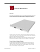
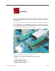
General Information Overview Xserve G5 is a server designed to mount into a rack; Apple recommends that you remove the Xserve G5 server from the rack before replacing or installing all parts except hard drives. You can replace hard drives while the server is operating and still in the rack. To identify versions of the Xserve G5, check the front panel. Xserve G5 and Xserve G5 (January 2005) include a slot-load optical drive and three hard drives.
Important: There are two versions of the Xserve G5 logic board that must be replaced like-for-like. Identify version 2 logic boards by the “DDR 2GB” (Double-Data-Rate, 2 gigabyte memory) label as shown below. Mounting in a Rack For information on mounting Xserve G5 in a rack, see the Xserve G5 User’s Guide. Tools You will need a medium and a small Phillips screwdriver and a small flat-blade screwdriver for some procedures. If the server is locked, you will also need the server’s Allen wrench key.
Before Opening the Server Serial Number Be sure to write down the server’s serial number. If the server’s software must be set up after service is complete, the serial number will be required for login. Unlocking the Server If the server is in the locked position (the yellow security LED on the front panel is on), use the Allen key that came with the server to unlock it.
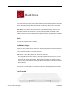
Hard Drive Xserve G5 and Xserve G5 (January 2005) include three hard drive bays at the front of the server; Xserve G5 (Cluster Node) includes just one drive bay. Drives come as modules attached to carriers; they are removed from or installed in the server as a unit. Note: Blank drive carriers, which may fill some of the hard drive bays, follow the same take-apart procedure as hard drives.
Procedure 1. Make sure the drive being replaced is not in use by any application and is not being shared by the server. (See the Mac OS X Server documentation for information about shared drives.) 2. Unmount the drive (by using the command-line tools or by dragging the disk icon to the Trash). 3. Press the handle on the front of the drive module so that the handle pops out. 4. Wait for the upper LED on the drive to go out. Then grasp the drive handle, and pull the drive module out of the server.
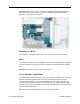
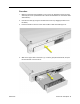
Opening the Server The server slides open from the front of the rack. The server’s top cover remains in place in the rack; the bottom housing (containing all internal components) should be placed on a sturdy, flat surface. Tools No tools are required for this procedure. You may, however, find a Phillips screwdriver useful in releasing the thumbscrews in step 1 below. Preliminary Steps Before you begin this procedure, write down the server’s serial number located on the back panel.
Procedure 1. Release the two thumbscrews at the front of the server. Note: The thumbscrews are captive and do not separate from the bottom housing. 2. Grasp the thumbscrews and slide the bottom housing forward part way to expose the two chassis levers. 3. While depressing both levers, pull the bottom housing all the way forward and remove it from the rack. Place the bottom housing on a sturdy, flat surface and ESD mat.
DIMMs Xserve G5 has eight Dual Inline Memory Module (DIMM) slots arranged in two banks. The slots accept Double-Data-Rate (DDR) Synchronous Dynamic Random-Access Memory (SDRAM) devices. Depending on your configuration, the computers ship with a pair of DIMMs installed in slot 1 of each DIMM bank. You can add DIMMs, provided they are installed in pairs of equal size, one per bank, from the center outward. Numbers marked on the logic board next to the DIMM slots illustrate how the pairs must be installed.
Important: Always install DIMMs in pairs of equal size. Memory from older Macintosh computers is not compatible with Xserve G5. Do not use older memory, even if it fits into the DIMM slots. Caution: Do not install 2 GB DIMMs in Xserve G5 main logic boards that did not previously have 2 GB DIMMs installed. Only Xserve G5 main logic boards labelled “DDR 2GB” accept 2 GB DIMMs. Refer to the Logic Board procedure for more information. Tools No tools are required for this procedure.
Procedure 1. Push down the ejectors on the DIMM slot. 2. Holding the DIMM by both top corners, lift it straight up out of the server. Warning: When removing or installing the DIMM, handle it only by the edges. Do not touch its connectors. Lift the DIMM straight up from the connector to remove it, and insert it straight down into the connector to install it. Do not rock the DIMM from side to side. Replacement Note: The DIMM is designed to fit into the slot only one way.
PCI or PCI-X Card In both Xserve G5/Xserve G5 (January 2005) and Xserve G5 (Cluster Node), there are two slots available for PCI or PCI-X expansion cards. The slots are on a riser card located at the back corner of the logic board.
Part Location 12 - Xserve G5 Take Apart PCI or PCI-X Card
Procedure Note: If you are removing a RAID card, refer to the following Take Apart topic “RAID Card.” 1. Release the thumbscrew that secures the card(s) to the back of the server and swing the metal cover open. Note: The thumbscrew is captive; you cannot remove it. 2. If any 12-inch card is installed, slide the card guide toward the front of the server to release the card. 3. Carefully pull the PCI card back from the connector on the PCI riser.
RAID Card and Standoff Tools No tools are required for this procedure. You may, however, find a Phillips screwdriver useful in releasing the thumbscrew in step 1 below. Preliminary Steps Before you begin, open the server and place the bottom housing on a sturdy, flat surface.
Procedure 1. Release the thumbscrew that secures the PCI/PCI-X card(s) to the back of the server and swing the metal cover open. Note: The thumbscrew is captive; you cannot remove it. 2. Carefully pull the RAID card back from the connector on the PCI riser. Then tilt the card so that its cables clear the enclosure, and lift the card a short distance out of the server. Warning: When removing or installing the RAID card, handle it only by the edges.
3. Turn the card over and disconnect the three RAID card cables. Replacement Note: Before installing the RAID card in the PCI riser, do the following: 1) Plug the backup battery cable into the connector on the card.
Replacing Standoff Follow these steps to replace a missing RAID card standoff.. 1. Mark the postion of the standoff, which will be installed in the hole in the corner of the card where shown above. Using your fingernail ,mark the position of the standoff on the black sheet of mylar insulation beneath the RAID card. 2. Remove the card from the PCI slot and using the square of double-stick tape included with the standoff, tape the black mylar insulation sheet to the bottom of the server.
PCI Riser Tools No tools are required for this procedure. You may, however, find a Phillips screwdriver useful in releasing the thumbscrew in step 1 below. Preliminary Steps Before you begin, open the server and place the bottom housing on a sturdy, flat surface.
Procedure If all cards installed are the standard 7-inch version, you can remove the cards and riser as a unit. However, if a RAID card or a 12-inch card is installed, you must disconnect the card from the riser before removing the riser from the server. (See step 2 below.) 1. Release the thumbscrew that secures the card(s) to the back of the server and swing the metal cover open. Note: The thumbscrew is captive; you cannot remove it. 2.
5. If you are replacing the riser, disconnect the PCI card(s) from the original riser and transfer them to the new riser. Warning: When removing or installing a PCI card, handle it only by the edges. Do not touch its connectors or any of the components on the card. Lift the card straight out from the connector to remove it, and insert it straight into the connector to install it. Do not rock the card from side to side and don’t force the card into the slot.
Power Supply Fan Duct Tools The only tool required for this procedure is a small flat-blade screwdriver. Preliminary Steps Before you begin, open the server and place the bottom housing on a sturdy, flat surface.
Procedure 1. Insert a small flat-blade screwdriver under the latch at the right side of the duct and pry the latch forward until it releases the duct from the enclosure. 2. Repeat step 1 for the left latch. 3. Holding the duct at both ends, lift it straight up and remove it from the server.
PCI Fan Duct The PCI fan is attached to a plastic duct; you remove the fan and duct as a unit. Tools The only tool required for this procedure is a small flat-blade screwdriver. Preliminary Steps Before you begin, open the server and place the bottom housing on a sturdy, flat surface.
Procedure 1. Insert a small flat-blade screwdriver under the latch at the side of the PCI fan duct and pry the latch forward until it releases the duct from the enclosure. 2. Holding the duct at both ends, lift it straight up a short distance. 3. Disconnect the PCI fan cable from the logic board. 4. Remove the PCI fan duct from the enclosure.
PCI Fan The PCI fan is located inside the PCI fan duct. Tools No tools are required for this procedure. Preliminary Steps Before you begin, do the following: • Open the server and place the bottom housing on a sturdy, flat surface. • Remove the PCI fan duct.
Procedure 1. Remove the three screws that mount the PCI fan to the PCI fan duct. 2. Remove the fan from the duct.
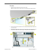
Optical Drive, Xserve G5 Note: The Xserve G5 (Cluster Node) server does not include an optical drive. Tools The only tool required for this procedure is a jeweler’s Phillips (#0) screwdriver. Preliminary Steps Before you begin, open the server and place the bottom housing on a sturdy, flat surface.
Procedure 1. Disconnect the optical drive cable from the optical drive. 2. Rotate the optical drive clip clockwise to release it. 3. Placing your thumbs on the tab on either side of the drive, carefully slide the drive back from the front bezel. Important: When removing or replacing the optical drive, be careful not to put pressure on the top of the drive or the top of the front bezel that covers the optical drive slot. 4. LIft the drive out of the server.
Replacement Note: Before installing the replacement drive, you must transfer the side brackets and the screws from the original drive to the replacement drive. 5. Remove the mounting screw for the left bracket and transfer the bracket to the new drive, using the same screw to secure it. 6. Remove the three mounting screws for the right bracket and transfer the bracket to the new drive, again using the same screws to secure it.
Optical Drive Cable, Xserve G5 Tools No tools are required for this procedure. Preliminary Steps Before you begin, do the following: • Open the server and place the bottom housing on a sturdy, flat surface. • Remove the power supply fan duct.
Procedure Warning: The optical drive cable is attached to the enclosure with adhesive on the underside of the cable. 1. Carefully pry the cable’s adhesive from the enclosure. 2. Disconnect the optical drive cable from the optical drive. 3. Disconnect the cable from the logic board and remove the cable from the server.
Processor Important: The heatsink is part of the processor in Xserve G5/Xserve G5 (January 2005); do not attempt to remove the heatsink from the processor. Tools The only tool required is a Phillips screwdriver. Preliminary Steps Before you begin, open the server and place the bottom housing on a sturdy, flat surface.
Procedure 1. Lift the processor cap straight up and remove it from the processor/heatsink. Note: The cap is attached to the processor by four pegs. Lift up in the areas illustrated below.
2. Using a Phillips screwdriver, remove the six screws that mount the heatsink and processor to the logic board. Replacement Note: There are two different types of processor mounting screws. When installing the processor, first replace the two shorter screws in the screw holes indicated by the squares in the illustration below. Then install the four longer screws in the screw holes indicated by the circles. 3. Carefully lift the heatsink and processor straight up and out of the server.
Fan Array Tools No tools are required for this procedure. You may, however, find a Phillips screwdriver useful in releasing the thumbscrews in step 3 below. Preliminary Steps Before you begin, do the following: • Open the server and place the bottom housing on a sturdy, flat surface. • Remove the power supply fan duct. • Remove the PCI fan duct.
Procedure 1. Disconnect the optical drive cable from the logic board and move the cable out of the way. 2. Press in the locking tab and release the fan cable from the logic board on the left side of the fan array. Repeat for the fan cable on the right side of the fan array. 3. Release the two thumbscrews that secure the fan array to the enclosure. Note: The thumbscrews are captive; you cannot remove them. 4. Remove the fan array from the server.
Locking Mechanism Rod Tools No tools are required for this procedure. Preliminary Steps Before you begin, open the server and place the bottom housing on a sturdy, flat surface.
Procedure 1. Pull back the latch to release the gear end of the locking mechanism rod. 2. Tilt up the gear end of the rod and remove the rod from the server. 3. If you are replacing the plastic gear on the end of the rod, slide the gear off the rod. Replacement Procedure 1. To install the gear, slide it onto the notched end of the locking rod, aligning the narrow end of the gear with the end of the rod. Note: Make sure the rib inside the gear engages with the notch in the rod.
2. To install the locking rod, insert the key-hole end of the rod into the port on the front bezel. Note: Make sure the small circle on the front of the rod points to the left. It should align with the “unlocked” symbol on the bezel.
Front Bezel Note: Although the illustrations for this procedure are based on Xserve G5/Xserve G5 (January 2005), the procedure is the same for Xserve G5 (Cluster Node). Tools The only tool required for this procedure is a Phillips screwdriver. Preliminary Steps Before you begin, open the server and place the bottom housing on a sturdy, flat surface.
Procedure 1. Using a Phillips screwdriver, remove the screws that attach the two front bezel brackets to the server, and remove the brackets. 2. Remove the screw that attaches the top of the bezel to the server. 3. Gently pull the front bezel forward and remove it from the server. Important: When removing or replacing the bezel, be careful not to put pressure on the top of the bezel over the optical drive slot.
Replacement Procedure 1. Transfer the system identifier and power buttons from the original front bezel to the replacement bezel. 2. Position the light pipes in the light pipe assembly into the double row of light pipe holes in the front bezel. 3. Replace the front bezel on the server, matching ports/projections with openings. 4. Replace the screw that secures the top of the bezel to the server. 5. Replace the two bezel brackets and their mounting screws.
Front Buttons Note: This procedure explains how to remove the power and system ID buttons from the front bezel. Tools The only tool required for this procedure is a Phillips screwdriver. Preliminary Steps Before you begin, do the following: • Open the server and place the bottom housing on a sturdy, flat surface. • Remove the front bezel.
Procedure 1. Holding the power button by the plastic tab, lift straight up and remove the button from the front bezel. 2. Repeat for the system ID button. Note: Take care in handling the buttons. The face of each button is loosely attached to the button LEDs and can easily separate. Replacement Note: Position the replacement buttons in the front bezel as illustrated.
Light Pipe Tools The only tool required for this procedure is a Phillips screwdriver. Preliminary Steps Before you begin, do the following: • Open the server and place the bottom housing on a sturdy, flat surface. • Remove the front bezel.
Procedure 1. Ease first one side and then the other side of the light pipe assembly from its opening in the front of the enclosure. 2. Remove the light pipe assembly from the server. Replacement Procedure 1. Position the light pipes in the replacement light pipe assembly into the double row of light pipe holes in the front bezel. 2. Replace the front bezel on the server, matching ports/projections with openings. 3. Replace the screw that secures the top of the bezel to the server. 4.
Front Panel Board Tools The only tool required for this procedure is a Phillips screwdriver. Preliminary Steps Before you begin, do the following: • Open the server and place the bottom housing on a sturdy, flat surface. • Remove the locking mechanism rod.
Procedure 1. Disconnect the FireWire cable from the front panel board. 2. Release the two locking levers on the front panel board cable connector and disconnect the cable from the front panel board. 3. Remove the two screws that mount the front panel board to the chassis. 4. Slide the board back slightly and release the two clips on either side of it. 5. Tilt the board up and remove it from the server.
Front Panel Board Cable Tools No tools are required for this procedure. Preliminary Steps Before you begin, do the following: • Open the server and place the bottom housing on a sturdy, flat surface. • Remove the PCI fan duct.
Procedure 1. Release the locking levers on the cable connectors and disconnect the front panel board cable from the front panel board and the logic board. 2. Remove the cable from the server.
FireWire Cable Tools No tools are required for this procedure. Preliminary Steps Before you begin, do the following: • Open the server and place the bottom housing on a sturdy, flat surface. • Remove the PCI fan duct.
Procedure 1. Disconnect the FireWire cable from the front panel board. 2. Disconnect the FireWire cable from the logic board and remove the cable from the server.
Power Cable Tools No tools are required for this procedure. Preliminary Steps Before you begin, do the following: • Open the server and place the bottom housing on a sturdy, flat surface. • Remove the power supply fan duct.
Procedure 1. Disconnect the optical drive cable from the logic board and move the cable connector out of the way. 2. Disconnect the power cable from the drive interconnect board. 3. Disconnect the power cable from the logic board and remove the cable from the server.
Hard Drive Cable The following procedure explains how to remove a three-headed hard drive cable from the Xserve G5 or Xserve G5 (January 2005) server. The procedure is similar for Xserve G5 (Cluster Node), except that the hard drive cable has just a single connector at each end. Tools No tools are required for this procedure. Preliminary Steps Before you begin, do the following: • Open the server and place the bottom housing on a sturdy, flat surface. • Remove the PCI fan duct.
Procedure 1. Disconnect the drive cable from the drive interconnect board. 2. Disconnect the drive cable from the logic board and remove the cable from the server.
RAID Card Cables Tools No tools are required for this procedure. You may, however, find a Phillips screwdriver useful in releasing the thumbscrew in step 1 below. Preliminary Steps Before you begin, do the following: • Open the server and place the bottom housing on a sturdy, flat surface. • Remove the PCI fan duct.
Procedure 1. Release the thumbscrew that secures the PCI/PCI-X card(s) to the back of the server and swing the metal cover open. Note: The thumbscrew is captive; you cannot remove it. 2. Carefully pull the RAID card back from the connector on the PCI riser. Then tilt the card so that its port and cables clear the enclosure, and lift the card a short distance out of the server. Warning: When removing or installing the RAID card, handle it only by the edges.
3. Turn the card over and disconnect the three RAID card cables from the card. 4. Disconnect the three RAID card cables from the drive interconnect board and remove the cables from the server. Replacement Note: Connect the three cables’ flat connectors to the RAID card and the connectors on the other end of the cables to the drive interconnect board, matching cables to connectors as illustrated above.
Replacement Note: Be sure to route the cables under the clear plastic card guide and behind the post that holds the PCI fan duct.
Drive Interconnect Board Tools No tools are required for this procedure. You may, however, find a Phillips screwdriver useful in releasing the thumbscrews in step 2 below.
Procedure 1.
2. Disconnect the following cables from the drive interconnect board: • power cable • hard drive cable 3. Release the three thumbscrews that secure the drive interconnect board to the chassis. Note: The thumbscrews are captive; you cannot remove them. 4. Pull the board back, tilt it up so that the connectors clear the chassis, and remove the board from the server.
Power Supply Tools No tools are required for this procedure. You may, however, find a Phillips screwdriver useful in releasing the thumbscrew in step 2 below. Preliminary Steps Before you begin, do the following: • Open the server and place the bottom housing on a sturdy, flat surface. • Remove the power supply fan duct.
Procedure 1. Release the thumbscrew that secures the power supply to the chassis. Note: The thumbscrew is captive; you cannot remove it. 2. Lift the front end of the power supply to disconnect it from the logic board. 3. Slide the power supply a short distance toward the front of the server so that the power receptacle clears the opening in the back panel. 4. Holding the power supply in both hands, remove it from the server.
Battery Tools No tools are required for this procedure. You may, however, find a flat-blade screwdriver useful in prying up the battery in step 1 below. Preliminary Steps Before you begin, open the server and place the bottom housing on a sturdy, flat surface.
Procedure 1. Pry up the battery from its holder. Note: You may first need to spread the two tabs on the holder slightly apart to release the battery. 2. Remove the battery from the server. Note: When replacing the battery, make sure the positive (+) end of the battery aligns with the + symbol on the battery holder.
Logic Board Tools The only tool required for this procedure is a Phillips screwdriver. Preliminary Steps Before you begin, open the server; place the bottom housing on a sturdy, flat surface; and remove the following: • DIMMs • PCI cards and PCI riser • processor • power supply fan duct • PCI fan duct • fan array • power supply Important: There are currently two versions of the Xserve main logic board that must be replaced like-for-like. 2 MB memory DIMMs can be installed on version 2 logic boards only.
Part Location Note: The version 2 logic board is shown above.
Procedure 1. Disconnect the FireWire cable from the logic board 2. Release the two locking levers on the front panel board cable connector and disconnect the cable from the logic board. 3. Disconnect the three-headed drive cable from the logic board. 4. Release the locking tab and disconnect the power cable from the logic board. 5. Fold the cables out of the way toward the front of the server.
6. Using a Phillips screwdriver, release the thumbscrew that secures the logic board to the chassis (indicated by a triangle in the illustration below). Note: The thumbscrew is captive; you cannot remove it. 7. Grasping the logic board by its long edges, move it forward and up slightly to release it from the four mounting pegs (indicated by squares in the illustration below). Caution: Be careful not to flex the logic board, which could damage the board or its components.
Important: When replacing the logic board, make sure the board’s connectors fit through the appropriate openings in the server’s back panel. Take special care to fit the clear plastic system identifier button through its opening. (The system identifier button is located low on the back panel, to the left of center.) Caution: Be careful not to flex the logic board, which could damage the board or its components.
Service Source Troubleshooting Xserve G5 © 2005 Apple Computer, Inc. All rights reserved.
General Information What’s New Hot-Pluggable Serial ATA Drives Xserve G5 and Xserve G5 (January 2005) include three hard drive bays at the front of the server; Xserve G5 (Cluster Node) includes just one hard drive. All versions support hotpluggable Apple serial ATA (SATA) drive modules. In the Xserve G5/Xserve G5 (January 2005) server, drive bays are numbered 1–3, beginning with the far left bay.
Ports The standard configuration of Xserve G5 includes the following ports on the back panel: two gigabit Ethernet ports, two FireWire 800 ports, two USB 2.0 ports, and a serial port that supports RS-232 or RS-422 connection. There is also one FireWire 400 port on the front of the server. System administrators or service providers can connect a laptop computer or terminal to the serial port and then use command-line tools to change settings on the server.
Resetting the PMU on the Logic Board The PMU (Power Management Unit) is a microcontroller chip that controls all power functions for the server. The PMU is a computer within a computer. Its function is to: • tell the server to turn on, turn off, sleep, wake, idle, etc. • manage system resets from various commands. • maintain parameter RAM (PRAM). • manage the real-time clock. Important: Be very careful when handling the logic board.
Power Supply Verification If the server fails to power on, first reset the PMU. Then follow the procedure outlined below to determine whether the problem is related to the power supply. Note: To verify the power supply, you need a volt meter. When connecting the volt meter leads to specific pins, make sure the power supply remains securely plugged into its connector on the logic board.
Entering Firmware Boot Commands From the Front Panel You can use the system identifier button on the Xserve G5 server’s front panel to initiate a limited number of firmware commands to the system without connecting a keyboard or monitor to the server. The commands are listed below; you enter each command with a combination of the system ID button and a specific light on the front panel. Note: If Open Firmware Security is turned on for the system, front panel mode is not available.
Status Lights The server’s status lights are shown in the figure and table below. While the illustration is based on Xserve G5, the callouts for the status lights are also accurate for Xserve G5 (Cluster Node).
Remote Monitoring Software Server Monitor Server Monitor is an application installed with Xserve system software that helps you monitor the following information about the server: • installed operating system • drive status and activity • power supply operation • enclosure and processor temperature • blower operation • security • network operation You can also use Server Monitor to get logs of activity and Apple System Profiler reports on remote servers.
Symptom Charts How to Use the Symptom Charts The Symptom Charts included in this chapter will help you diagnose specific symptoms related to the product. Because cures are listed on the charts in the order of most likely solution, try the cures in the order presented. Verify whether or not the product continues to exhibit the symptom. If the symptom persists, try the next cure. Note: If a cure instructs you to replace a module, reinstall the original module before you proceed to the next cure.
Memory error message appears on the screen 1. Reseat the DIMMs. 2. Verify that the correct SDRAM DIMMs are installed. 3. Run Xserve Remote Diagnostics. (Be sure to run XRD 1.0.2 or later if 2 GB DIMMs are installed.) If the test finds bad memory, replace the DIMMs one at a time and test until all bad DIMMs are replaced with known-good modules. Flashing question mark appears on the screen 1. Reseat the drive module in the first drive bay. 2.
6. Replace the logic board. Note: When installing the new logic board, make sure the ports and ID button on the back of the board align with the openings in the chassis. System shuts down intermittently 1. Verify that the system ID button on the back of the logic board aligns with the opening in the chassis back panel. If it does not, realign the logic board. 2. Make sure the power cord is plugged in firmly. 3. Check that the power source is turned on and the correct voltage is present. 4.
Error Lights Note: Error lights flash before system software loads. Server activity lights flash two times at startup Two flashes mean that no RAM is installed or detected. 1. If no DIMM is present, install a known-good DIMM in the top slot and try again. 2. Reseat the DIMMs. 3. Run Xserve Remote Diagnostics. (Be sure to run XRD 1.0.2 or later if 2 GB DIMMs are installed.) If the test finds bad memory, replace the DIMMs one at a time and test until all bad DIMMs are replaced with known-good modules. 4.
Video Screen is black, but activity lights flash at startup, drive operates, blowers are running, and power LED is lit 1. Verify that the system ID button on the back of the logic board aligns with the opening in the chassis back panel. If it does not, realign the logic board. 2. Check video card connections and connector pins. 3. Test with a known-good monitor. Replace the monitor, if necessary. 4. Remove all third-party devices. 5. Reseat the video card. 6. Clear parameter RAM.
Hard Drive Flashing question mark appears on the screen 1. Reseat the drive module in the first drive bay. 2. Start up from the system restore CD and check to see if the hard drive shows up on the desktop. If it does, go to step 3. If it does not, go to step 5. 3. Run Disk Utility. Update the driver and restart the server. 4. Reinstall system software using the system restore CD that came with the server. 5. Replace the drive module in the first drive bay.
Disc will not eject 1. If the server is locked, unlock it. 2. Verify the disc is not in use. 3. Drag the disc icon to the trash or select it and press Command-E. 4. Restart the server while holding down the mouse button. 5. Verify that the bezel over the slot is not bent. If it is, gently bend it back into position. 6. Reseat the optical drive cable at both connectors. 7. Replace the optical drive cable. 8. Replace the optical drive. USB Devices At startup, cursor does not move with the Apple mouse 1.
FireWire Devices FireWire device connected to port on back panel: No FireWire device icon appears on the desktop 1. If the server is locked, unlock it. 2. Verify that the FireWire device is turned on and the FireWire cable is securely connected to the device and the server. 3. If the device requires external power, make sure it is plugged in. 4. Check that the FireWire device is listed in Apple System Profiler. If it is, go to step 5. If it is not, go to step 6. 5.
Network Problems Server cannot be seen on network 1. Open the Network system preference pane and select the built-in Ethernet option. Verify that you can now see devices on the network. 2. If only one Ethernet port is in use, verify that it is the lower port. If it is not, move the Ethernet cable to the lower port. 3. Boot the server from the Net-install CD. Go to another computer on the same subnet and start Server Assistant. If the server can be seen, the server hardware should be functioning correctly.
Service Source Views Xserve G5 © 2005 Apple Computer, Inc. All rights reserved.
Internal Views, Xserve G5 Exploded View Dual-Slot Riser Card 922-6330 Logic Board 661-3153 Battery 922-4028 Power Supply 661-3155 DIMM Slots (8) 256 MB 661-3170 512 MB 661-3154 1 GB 661-3171 PCI Fan 922-6350 PCI Fan Duct 922-6377 Processor 661-3152 PS Fan Duct 922-6376 Drive Interconnect Board 922-6349 Front Panel Board 922-6344 SATA Hard Drive 80 GB 661-3149 250 GB 661-3148 FireWire Cable 922-6346 Internal Views, Xserve G5 Front Fan Panel Array Board 922-6345 Cable 922-6347 Optical Drive Cable 9
Logic Board USB FireWire 2.
External Views, Xserve G5 Front Panel FireWire 400 Port System Identifier Button/Light Built-in Ethernet Link Light (Port 2) System Activity Lights Optical Drive Enclosure Lock and Status Light Drive Module Status Light On/Standby Button and Light Apple Drive Module Bays (3) Drive Module Activity Light Securing Thumbscrews (2) Built-in Ethernet Link Light (Port 1) Back Panel Gigabit Ethernet Port(s) Ethernet Link Lights Ethernet Activity Lights Power Socket Serial Console Port Serial Number Label