INSTALLATION AND OPERATING INSTRUCTIONS Atmospheric Model 130A Above-Ground Pool Spa Heater READ THIS MANUAL BEFORE INSTALLATION OR OPERATION. WARNING: If the information in these instructions are not followed exactly, a fire or explosion may result causing property damage, personal injury or death. FOR YOUR SAFETY Do not store or use gasoline or other flammable vapors and liquids or other combustible materials in the vicinity of this or any other appliance.
Water Chemistry • Automatic chemical dosing devices and salt chlorinators are usually more efficient in heated water, unless controlled, they can lead to excessive chlorine level which can damage your heater. • Further advice should be obtained from your pool or spa builder, accredited pool shop, or chemical supplier for the correct levels for your water. WATER CHEMISTRY NOTE: Corrosive water voids all warranties. Chemical imbalance can cause severe damage to your heater and associated equipment.
Table of Contents / Safety TABLE OF CONTENTS WATER CHEMISTRY . . . . . . . . . . . . . . . . . . . . . . . . . .ii TABLE OF CONTENTS . . . . . . . . . . . . . . . . . . . . . . . .3 SAFETY . . . . . . . . . . . . . . . . . . . . . . . . . . . . . . . . . . . .3 Safety Warnings . . . . . . . . . . . . . . . . . . . . . . . . . . .3 Water Temperature Safety . . . . . . . . . . . . . . . . . . .4 INTRODUCTION . . . . . . . . . . . . . . . . . . . . . . . . . . . . .4 Ratings and Certifications . . . . . . . .
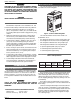
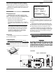
Safety / Introduction WARNING MODEL IDENTIFICATION GASOLINE, AS WELL AS OTHER FLAMMABLE MATERIALS AND LIQUIDS (ADHESIVES, SOLVENTS, ETC.), AND THE VAPORS THEY PRODUCE, ARE EXTREMELY DANGEROUS. DO NOT HANDLE, USE, OR STORE GASOLINE OR OTHER FLAMMABLE OR COMBUSTIBLE MATERIALS IN THE VICINITY OF A HEATER. The model identification number and heater serial number are found on the heater rating plate. CAUTION VERIFY PROPER OPERATION AFTER SERVICING.
Introduction / Installation When ordering parts, specify the model and serial number of the heater. When ordering under warranty conditions, specify the date of installation. Records of the installation must be provided, when requested, to substantiate a claim. Debits for defective replacement parts will not be accepted and will only be replaced in kind per the manufacturer's standard warranties.
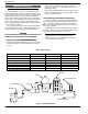
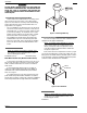
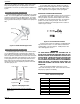
Installation WARNING DO NOT INSTALL WITHIN 3 FEET OF A HEAT PUMP OR AN OUTDOOR CONDENSING UNIT. STRONG AIR INTAKE FROM THIS TYPE OF EQUIPMENT CAN DISTURB THE COMBUSTION PROCESS AND CAUSE DAMAGE OR PERSONAL INJURY. HEATER WITH HIGH-WIND TOP OUTDOOR STACKLESS TOP Heaters must not be installed under an overhang of less than 3 ft from the top of the heater. Three sides must be open in the area under the overhang.
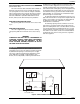
COMBUSTION AND VENTILATION AIR (INDOOR UNITS ONLY) The heater must have both combustion and ventilation air. Minimum requirements for net free air supply openings are one opening that is 12 inches from the ceiling for ventilation, and one opening that is 12 inches from the floor for combustion air as outlined in the latest edition of the National Fuel Gas Code, ANSI Z223.1(Canada-CAN/CGA-B149.1 and B149.2) and any local codes that may have jurisdiction.
Installation CAUTION THE HEATER AND ITS MANUAL SHUT-OFF VALVE MUST BE DISCONNECTED FROM THE GAS SUPPLY DURING ANY PRESSURE TESTING OF THAT SYSTEM AT TEST PRESSURES IN EXCESS OF 1/2 PSIG (3.5 KPA). THE HEATER AND ITS GAS CONNECTIONS SHALL BE LEAK TESTED BEFORE PLACING THE APPLIANCE IN OPERATION. USE SOAPY WATER FOR LEAK TEST. DO NOT USE OPEN FLAME. NOTE: Do not use Teflon tape on gas line pipe thread. A flexible pipe sealant suitable for LP gases is recommended.
Installation Figure 9C. Honeywell MV Gas Valve. ELECTRONIC IGNITION GAS VALVES Figure 10. Location of Gas Pressure Adjustment. PIPE SIZING FOR GAS CONNECTIONS Table 5. Maximum Equivalent Pipe Length. Maximum Equivalent Pipe Length Natural Gas 1000 BTU/FT3 0.60 Specific Gravity @ 0.5 in. WC Pressure Drop Propane Gas 2500 BTU/FT3 1.53 Specific Gravity @ 0.5 in.
Installation High-temperature CPVC header flanges and header flange nuts are available as an option. If there is any possibility of back-siphoning when the pump stops, it is recommended that a check valve (or valves) also be installed in the system. INTERNAL AUTOMATIC BYPASS VALVE A built-in automatic bypass valve is provided in the In/Out header. The internal bypass valve automatically responds to changes in water pressure in the piping system.
Installation ELECTRICAL CONNECTIONS Be sure that electrical service to the heater has proper overload fuse or circuit breaker protection, wire size and connections which comply with all applicable codes. NOTE: If it is necessary to replace any of the original wiring, use 105°C wire or its equivalent, and/or 150°C wire or its equivalent, like the original wiring. See Figures 18 and 19 for wire ratings.
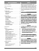
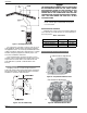
Installation HI Limit HI Limit Manual BK BK (In/Out) Thermostat Y/BK AGS (In/Out) V/BK Switch To Firemans Switch (field installed) Optional O Gas Valve Water Press Roll Out R O Switch TH V/BK TH/PP PP Switch Valve Pilot R W - + Generator Figure 18. Wiring Diagram - Millivolt Models.
Operation FOR YOUR SAFETY READ BEFORE OPERATING WARNING: If you do not follow these instructions exactly, a fire or explosion may result causing property damage, personal injury or loss of life. A. This appliance is equipped with an ignition device which automatically lights the burners. Do not try to light the burners by hand. B. BEFORE OPERATING, smell all around the appliance area for gas. Be sure to smell near the floor because some gas is heavier than air and will settle on the floor.
Operation FOR YOUR SAFETY READ BEFORE OPERATING WARNING: If you do not follow these instructions exactly, a fire or explosion may result causing property damage, personal injury or loss of life. A. B. *If you cannot reach your gas supplier, call the fire department. This appliance has a pilot that must be lit by hand. When lighting the pilot, follow these instructions exactly. BEFORE LIGHTING, smell all around the appliance area for gas.
Operation POST START-UP INSPECTION Feel the inlet and outlet pipes. Outlet pipe should be only slightly warmer than the inlet. It should not be hot. WARNING SHOULD OVERHEATING OCCUR OR THE GAS SUPPLY FAIL TO SHUT OFF, TURN OFF THE MANUAL GAS CONTROL TO THE APPLIANCE. With the heater on, remove the door and make a visual check of the pilot and burner. The flame should be blue with a well-defined pattern. Figure 20. Correct Main Burner Flame Pattern.
Maintenance / Service MAINTENANCE The following preventative maintenance is to be performed one month after start-up and semi-annually thereafter. 1. Inspect top of heater and drafthood for soot, a sticky black substance around finned tubes and "V" baffles, and open flue gas passageways. Any visible soot should be cleaned for proper operation. See the Desooting Procedure in the Service Section. 2. Clean main burners and pilot burner of dust and lint. 3.
Service 3. Remove defective high limit and replace with a new high limit. BURNER TRAY REMOVAL 4. Replace inspection panel. 1. Shut off main electrical power switch to heater. 2. Shut off gas upstream of heater. PILOT SAFETY - MILLIVOLT MODELS 3. Remove front door. Heaters equipped with the standing pilot (Millivolt system) have pilot generators which act as a safety device to shut off the flow of gas to the main burners and the pilot burner in case the pilot flame is extinguished.
Service GAS VALVE REMOVAL 1. Remove burner tray from heater as described in the Burner Tray Removal section.. 2. Disconnect pilot tubing (if removing a Millivolt valve). 3. Disconnect wires to gas valve. 4. Unscrew gas valve from manifold. 5. Reverse above procedure to reinstall. MAIN BURNER AND ORIFICE REMOVAL 1. Remove burner tray. 2. Remove screws from rear burner hold-down bracket.
Service Auger with Carbide Tip Extension Pieces (2) Wire Brush Figure 32. Tube Cleaning Tool. 1. Disconnect pilot tubing and wires from gas valve. 2. Remove pilot assembly from burner tray. 2. Remove "V" baffles from heat exchanger, including side baffles. 3. Remove pilot from bracket. 3. Remove burner tray. 4. Remove pilot orifice and air opening (Honeywell MV unit only), and clean with wire or small brush. 4.
Troubleshooting TROUBLESHOOTING MECHANICAL These instructions are intended for use by qualified personnel who are specifically trained and experienced in the installation of this type of heating equipment and related system components. Installation and service personnel may be required by some states to be licensed. Persons not qualified shall not attempt to install this equipment nor attempt repairs according to these instructions.
Troubleshooting ELECTRICAL STANDING PILOT MILLIVOLT The following information is presented for use by qualified service personnel only. 1. Filter must be on with adequate water flow through heater. 2. Gas valve must be in "ON" position. Thermostat set higher than pool water temperature. 3. Jumpers are for temporary check only. If left in place, they could cause the heater to burn up.
Troubleshooting TERMINAL BLOCK WIRING Figure 35. Terminal Block Wiring. 1. Raw Output (700mV± 100) Pilot generator disconnected from valve (knob must be held down to keep pilot on). White – Negative Red + Positive 2. Pilot Load (500mV± 100) Pilot generator connected to valve-Power applied to pilot solenoid. TP(Thermopile-Robertshaw) PP(Power Pile-Honeywell) TH TP – Common (Invensys) TH PP – Common (Honeywell) 3.
Troubleshooting ELECTRONIC CONTROL LOGIC FLOWCHART START Turn knob to a desired temperature zone. Turn switch ON. After (6) seconds, does the igniter spark? •Check water flow. Pressure switch is set for 1.75 PSI. •Turn knob counterclockwise (setpoint may be lower than actual temperature) •Check High Limit. Both are normally closed. •Check Roll-Out switch. Must be normally closed. •Check wiring in control box against wiring diagram. No Yes Does the burner tray light? Ensure the heater is OFF.
Illustrated Parts List Page 24
Illustrated Parts List 1-P 3-P 5-P 7-P 4-P 8-P 2-P 6-P HONEYWELL MILLIVOLT PILOT Page 25
Illustrated Parts List CALL OUT B 1-B DESCRIPTION Plastic Green Plastic Gray BURNER TRAY Burner Tray w/Burners (Sea Level)* 011578F 011578F Burner Tray w/o Burners (Sea Level)* 011579F 011579F Burner Tray w/Gas Valve Natural MV 011580F 011580F Burner Tray w/Gas Valve Propane MV 011581F 011581F Burner Tray w/Gas Valve Natural DSI 011582F 011582F Burner Tray w/Gas Valve Propane DSI 011583F 011583F 2-B Burner Hold Down Kit 011584F 011584F 3-B Burner 301210/10 301210/10 4-B Burner Orifice Nat.
Illustrated Parts List CALL OUT M 1-M 2-M 3-M 4-M 5-M 6-M 7-M 8-M 9-M 10-M P 1-P 2-P 3-P 4-P 5-P 6-P 7-P 8-P R 1-R 2-R S 1-S 2-S 3-S 4-S 5-S 6-S 7-S 8-S 9-S V 1-V 2-V 3-V 4-V 5-V DESCRIPTION MISCELLANEOUS COMPONENTS Pressure Switch 1.