Model AM7 Installation Guide NOTE: This product is intended for installation by a professional installer only! Any attempt to install this product by any person other than a trained professional may result in severe damage to a vehicle’s electrical system and components.
Bitwriter®, Code Hopping™, Doubleguard®, ESP™, FailSafe®, Ghost Switch™, Learn Routine™, Nite-Lite®, Nuisance Prevention® Circuitry, Revenger®, Silent Mode™, Soft Chirp®, Stinger®, Valet®, Vehicle Recovery System®, VRS®, and Warn Away® are all Trademarks or Registered Trademarks of Directed Electronics. New Software Compatibility for 103T Keypad The Bitwriter® (p/n 998T) requires chip version 2.2 or newer to program this unit.
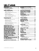
table of contents warning! safety first . . . . . . . . . . . . . . . . . . . . . . . . . 4 installation points to remember . . . . . . . . . . . . . . . . . 5 before beginning the installation . . . . . . . . . . . . . 5 after the installation. . . . . . . . . . . . . . . . . . . . . . 5 deciding on component locations . . . . . . . . . . . . . . . . 6 locations for the control module . . . . . . . . . . . . . . 6 locations for the siren . . . . . . . . . . . . . . . . . . . . .
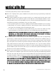
warning! safety first The following safety warnings must be observed at all times: ■ Due to the complexity of this system, installation of this product must only be performed by an authorized Directed Electronics dealer. ■ When properly installed, this system can start the vehicle via a command signal from the remote control transmitter. Therefore, never operate the system in an area that does not have adequate ventilation.
installation points to remember IMPORTANT! This product is designed for fuel-injected, automatic transmission vehicles only. Installing it in a standard transmission vehicle is dangerous and is contrary to its intended use. before beginning the installation ■ Please read this entire installation guide before beginning the installation. The installation of this remote start system requires interfacing with many of the vehicle’s systems.
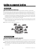
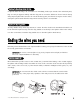
deciding on component locations locations for the siren Some things to remember about mounting the siren: ■ Keep it away from heat sources, such as radiators, exhaust manifolds, turbochargers, and heat shields. ■ Mount it where a thief cannot easily disconnect it, whether the hood is open or shut. Both the siren and its wires should be difficult to find. This usually involves disguising the wire to look like a factory harness. ■ We recommend against grounding the siren to its mounting screws.
■ Some good control module locations are: Above the glove box, inside the center console, above the underdash fuse box, or above the radio. mounting the antenna The antenna position should be discussed with the vehicle’s owner prior to installation, since the antenna may be visible to the vehicle’s operator. The best location for the antenna is centered high on either the front or rear windshield. For optimal range, the antenna should be mounted vertically.
locations for valet/program switch IMPORTANT! When the vehicle is delivered, please show the user where this switch is located and how to disarm the system with it. Ensure that the location you pick for the switch has sufficient clearance to the rear. The switch should be well hidden. It should be placed so passengers or stored items (such as in a glove box or center console) cannot accidentally hit it. The switch fits into a 9/32-inch hole. This system has Remote Valet.
locations for the optional starter kill relay If optional starter kill relay or its connections are immediately visible upon removal of the under-dash panel, they can easily be bypassed. Always make the relay and its connections difficult to discern from the factory wiring! Exposed yellow butt connectors do not look like factory parts, and will not fool anyone! For this reason, routing the optional starter kill wires away from the steering column is recommended.
finding the 12V switched ignition wire The ignition wire is powered when the key is in the run or start position. This is because the ignition wire powers the ignition system (spark plugs, coil) as well as the fuel delivery system (fuel pump, fuel injection computer). Accessory wires lose power when the key is in the start position to make more current available to the starter motor. How to find (+)12V ignition with your multimeter: 1. Set to DCV or DC voltage (12V or 20V is fine). 2.
finding the accessory wire An accessory wire will show +12V when the key is in the accessory and run positions. It will not show +12V during the cranking cycle. There will often be more than one accessory wire in the ignition harness. The correct accessory wire will power the vehicle's climate control system. Some vehicles may have separate wires for the blower motor and the air conditioning compressor. In such cases, it will be necessary to add a relay to power the second accessory wire.
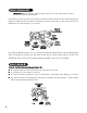
finding a (+) parking light wire The (+) parking light wire is often found near the switch. Many cars have the switch built into the turn signal lever, and in these cars the parking light wire can be found in the steering column. The same wire is often available in the kick panel or running board. NOTE: Many Toyotas, as well as many other Asian vehicles, send a (-) signal from the switch to a relay. The relay then sends (+)12V to the bulbs.
Once you have determined the wire color, the easiest place to connect to the wire is often at the kick panel, at the windshield pillar, or in the running board. When an easy location is not available, running a wire to the domelight itself is often the best solution. How to find a door pin switch trigger wire with your multimeter: 1. Set to DCV or DC voltage (12V or 20V is fine). 2. In most Fords, fasten the (-) probe of the meter to chassis ground.
primary harness (H1), 12-pin connector H1/1 H1/2 H1/3 H1/4 H1/5 H1/6 H1/7 H1/8 ______ ______ ______ ______ ______ ______ ______ ______ RED/WHITE RED BROWN (-) 200 mA CHANNEL 2 VALIDITY OUTPUT (+) CONSTANT POWER INPUT (+) SIREN OUTPUT EMPTY NOT USED BLACK (-) CHASSIS GROUND INPUT VIOLET (+) DOOR TRIGGER INPUT, ZONE 3 BLUE (-) MULTIPLEXED INPUT, ZONE 4 GREEN (-) DOOR TRIGGER INPUT, ZONE 3 H1/9 ______ BLACK/WHITE H1/10 ______ WHITE/BLUE H1/11 ______ WHITE H1/12 ______ ORANGE (-) 200 mA DO
door lock harness, 3-pin connector 1 ______ 2 ______ 3 ______ LIGHT BLUE (+) LOCK (-) UNLOCK OUTPUT EMPTY NOT USED GREEN (-) LOCK (+) UNLOCK OUTPUT Note: Refer to TechTip 1041 for wiring information.
heavy gauge relay satellite wiring diagram 1 2 3 4 5 6 7 8 ______ ______ ______ ______ ______ ______ ______ ______ PURPLE GREEN RED ORANGE PINK RED PINK/WHITE RED/WHITE (+) STARTER OUTPUT TO STARTER (STARTER SIDE) STARTER INPUT FROM IGNITION (KEY SIDE) (+) HIGH CURRENT 12V INPUT (+) OUTPUT TO ACCESSORY CIRCUIT (+) OUTPUT TO PRIMARY IGNITION CIRCUIT (+) (30A) HIGH CURRENT 12V INPUT (+) OUTPUT TO SECOND IGNITION CIRCUIT (+) (30A) HIGH CURRENT 12V INPUT remote start harness (H3), 5-pin connector H3/1 _____
primary harness (H1) wire connection guide H1/1 RED/WHITE channel 2, 200mA (-) output When the system receives the code controlling Channel 2, for longer than 1.5 seconds, the red/white wire will supply an output as long as the transmission continues. This is often used to operate a trunk/hatch release or other relay-driven function. IMPORTANT! Never use this wire to drive anything but a relay or a low-current input! The transistorized output can only supply 200 mA of current.
H1/3 BROWN (+) siren output Connect this to the red wire of the siren. Connect the black wire of the siren to (-) chassis ground, preferably at the same point you connected the control module’s black ground wire. See Features Description section for horn output. H1/5 BLACK (-) chassis ground connection Remove any paint and connect this wire to bare metal, preferably with a factory bolt rather than your own screw. (Screws tend to either strip or loosen with time.
H1/7 BLUE (-) multiplex input, zone 4 Inputs shorter than 0.8 seconds will trigger the Warn Away response, while inputs longer than 0.8 seconds will trigger the full alarm sequence. If installing an optional Directed Electronics dual stage sensor, connect both the blue and the green wires of the optional sensor to this input. This wire will report Zone 4. H1/8 GREEN (-) door trigger input, zone 3 Most vehicles use negative door trigger circuits.
H1/10 WHITE/BLUE remote start (-) activation input This input comes from the factory set to 2 activation pulses. This means that it is necessary to have 2 consecutive ground pulses on the white/blue wire for the remote start to activate or to deactivate. The same holds true for the remote control activation when set to a two pulse setting it is necessary to press the button twice for the remote start to activate or deactivate.
(-) Light Flash Output NOTE: For parking light circuits that draw 10 amps or more, the internal jumper must be switched to a (-) light flash output. (See the Internal Programming Jumper section of this guide.) P/N 8617 or a standard automotive SPDT relay must be used on the H1/2 light flash output harness wire. H1/12 ORANGE (-) ground-when-armed output This wire supplies a (-)500 mA ground as long as the system is armed. This output ceases as soon as the system is disarmed.
■ 30-second (60, 90) timed: Output that will send a continuous signal for 30 seconds. Bitwriter® programs 1 to 90 seconds. IMPORTANT! Never use this wire to drive anything but a relay or a low-current input! This transistorized output can only supply 200 mA, and connecting directly to a solenoid, motor, or other high-current device will cause the module to fail.
H2/6 LIGHT GREEN/BLACK (-) factory disarm output This wire sends a negative pulse every time the remote start is activated or the doors are unlocked. This can be used to pulse the disarm wire of the vehicle's factory anti-theft device. Use a relay to send a (-) or (+) pulse to the disarm wire as shown in the following diagrams.
relay satellite wire connection guide The five heavy gauge wires coming from the large connector are used to energize high current circuits in the vehicle. It is crucial that these connections are well-made and capable of handling the current demands. For this reason, Scotch-Locks, T-taps and other such connectors are strongly discouraged. PURPLE (+) starter output After cutting the starter wire connect the PURPLE wire to the end going to the starter motor.
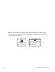
remote start secondary harness (H3) wire connection guide H3/1 BLACK/WHITE neutral safety switch input Connect this wire to the provided toggle (override) switch as shown in figure A. Connect the other wire from the toggle switch to the PARK/NEUTRAL switch in the vehicle. This wire will test with ground with the gear selector either in PARK or NEUTRAL. This will prevent the vehicle from accidentally being started while in a drive gear.
H3/3 BROWN (+) brake switch input, zone 1 This wire MUST be connected to the vehicle's brake light wire. This is the wire that shows (+) 12V when the brake pedal is depressed. The remote start will be disabled or shut down any time the brake pedal is depressed. This wire will also trigger the security system if the brake pedal is pressed while the system is armed and will report Zone 1. H3/4 GRAY (-) hood pinswitch input, zone 1 This wire MUST be connected to hood pinswitch.
neutral safety switch interface Some vehicles do not have an electrical neutral safety switch. Instead, a mechanical neutral safety switch that physically interrupts the starter wire is used when the vehicle is in any drive gear. If the remote start is interfaced before this switch, it will provide protection from starting in gear. However, some vehicles combine the column shift mechanism and the mechanical neutral safety switch into one mechanical part.
If the starter engages and the vehicle is a General Motors product or Dodge Dakota pickup, refer to the following text and diagrams for an alternative shut-down method which will prevent the starter from engaging. If the vehicle is not a General Motors product or a Dodge Dakota pickup, please call Directed Electronics Technical Support for an alternative shut-down method.
General Motors trucks, sport utility vehicles and column shifting passenger vehicles: Pre-1996 Dodge Dakota pickups with 2.
bypassing GM vehicle anti-theft systems (VATS) Vehicles with the GM VATS (Pass Key) systems have a resistor embedded in the ignition key. If the VATS decoder module does not measure the proper resistance when the vehicle is started, the starter and fuel pump may be disabled for up to ten minutes. An optional "VATS pack" of resistors is available (p/n 652T). One of the resistors in the pack will match the resistor in the key.
1995 and newer vehicle anti-theft systems (immobilizers) 1995 and newer vehicle anti-theft systems (immobilizers) require a bypass module. The bypass module allows for easy interfacing, while still maintaining the OEM system’s integrity.
ceiver will excite the transponder, which is located (but not visible) in the head of the ignition key. The key transponder will then send a unique code back to the transceiver for evaluation. If the code matches a valid code of the system, the vehicle will be allowed to start. Most of these transponder-based systems can be bypassed using p/n 555U. Some may require additional parts from the vehicle manufacturer. Consult you dealer for the applications.
shock sensor harness, 4-pin connector GREEN (-) multiplex input, zone 2 Inputs shorter than 0.8 seconds will trigger the Warn Away® response, while inputs longer than 0.8 seconds will trigger full alarm sequence and report Zone Two. If installing an optional Directed Electronics dual stage sensor, connect to the green wire as shown below. The diagram below eliminates the need for diodes to isolate the sensors.
tach learning To learn the tach signal: 1. Start the vehicle with the key. 2. Within 5 seconds, press and HOLD the Valet/Program switch. 3. The LED will light constant when the tach signal is learned. 4. Release the Valet/Program switch.
tach threshold on/off In most cases, this jumper can be left in the OFF position. Some new vehicles use less than 12 volts in their ignition systems. The unit may have trouble learning the tach signal in these vehicles. Changing the jumper to the ON setting changes the trigger threshold of the digital tach circuit so it will work properly with these vehicles. These vehicles include many newer Dodge/Chrysler/Plymouths, such as the Neon Cirrus/Stratus/Breeze and LH-based cars.
3. Choose. Within 10 seconds, press and release the Program switch the number of times corresponding to the desired channel listed below. Once you have selected the channel, press the switch once more and HOLD it. The LED will flash and the horn will honk (if connected) to confirm the selected channel. Do not release the Program switch.
If you want to program Channel 3 after programming Channel 1, release the Valet/Program switch, press it twice and release it to advance to Channel 3. Then press it once more and HOLD it. The horn will honk three times (if connected) and the LED will flash three times to confirm it is ready to receive the code from the transmitter. Learn Routine will be exited if: ■ Door is closed. ■ Ignition is turned off. ■ Program switch is pressed too many times. ■ More than 15 seconds between steps.
and ................operate............................Channel 5 and and and ................operate............................Channel 6 operate .........................rear defogger multi-level security arming Multi-Level Security Arming is a feature that allows the user to select which of the system's inputs or sensors will be active and which will be bypassed when the system is armed. (See Table of Zones section of this guide.
system features learn routine The System Features Learn Routine™ dictates how the unit operates. Due to the number of features, the features have been divided into two menus. It is possible to access and change any of the feature settings using the Valet/Program switch. However, this process can be greatly simplified by using the Bitwriter®. Any of the settings can be changed and then assigned to one of up to four transmitters, a feature called Owner Recognition.
6. Release. The Valet/Program switch can now be released. You can advance from feature to feature by pressing and releasing the Valet/Program switch the number of times necessary to get from the feature you just programmed to the feature you wish to access. For example, in Menu One, if you just programmed Feature 1-2 and you next want to program Feature 1-3 to off, release the Valet/Program switch. Press and release it once to advance from Feature 1-2 to Feature 1-3. Then press it once more and HOLD it.
feature menus The default settings are indicated in bold type. Features that have additional settings that can be programmed using the Bitwriter® are indicated with an asterisk (*).
menu #2 - advanced features FEATURE NUMBER ONE-CHIRP SETTING (DEFAULT) TWO-CHIRP SETTING 2-1 30 second siren duration* 60 second siren duration* 2-2 Nuisance Prevention Circuitry ON Nuisance Prevention Circuitry OFF 2-3 Progressive door trigger Instant door trigger 2-4 Disarm from Valet, 1 pulse Disarm from Valet, 2-5 pulses 2-5 Door sensor bypass chirp ON Door sensor bypass chirp OFF 2-6 Ignition controlled domelight ON Ignition controlled domelight OFF 2-7 Unlock output 1 pulse Unl
menu #3 - remote start options FEATURE ONE-CHIRP SETTING (DEFAULT) TWO-CHIRP SETTING 3-1 Engine checking ON Engine checking OFF 3-2 Engine checking TACH Engine checking VOLTAGE 3-3 Run time: 12 minutes Run time: 24 or 60 minutes 3-4 Parking lights flashing Parking lights constant 3-5 Crank time: 0.6 seconds (1) 0.8 (2), 1.0 (3), 1.2 (4), 1.4 (5), 1.6 (6), 1.8 (7), 2.0 (8), 4.0 (9) sec. 3-6 Voltage check - high Voltage check - low 3-7 Short Run/Turbo–1 min.
feature descriptions The features of the system are described below. Features that have additional settings that can be selected only when programming with the Bitwriter® are indicated by the following icon: menu #1 - basic features 1-1 ACTIVE/PASSIVE ARMING: When active arming is selected, the system will only arm when the transmitter is used. When set to passive, the system will arm automatically 30 seconds after the last door is closed.
1-8 FORCED PASSIVE ARMING ON/OFF:: To use this feature, passive arming must be selected in Feature 1-1. When turned on, forced passive arming will ensure that the system will passively arm, even if a zone is left open or invalid. Forced passive arming occurs one hour after the ignition is turned off. 1-9 AUTOMATIC ENGINE DISABLE (AED) ON//OFF: AED is a full-time, passive starter disable that works independently of the security system.
2-2 NUISANCE PREVENTION® CIRCUITRY (NPC) ON/OFF:: NPC stops repeated triggering of the same zone. If one zone is triggered three times in one hour, that zone is bypassed for one hour, starting from the time of the third trigger. During that hour, if the system sees a trigger on that zone again, the system resets the one hour timer. If one hour passes and the zone has not triggered again, the zone is activated and can trigger the system again.
2-9 FACTORY ALARM DISARM WITH CHANNEL 2: In the default setting the factory alarm disarm output will disarm the factory alarm system any time the button(s) controlling Channel Two is pressed. 2-10 FACTORY ALARM DISARM—WITH UNLOCK, BEFORE UNLOCK, REMOTE START ONLY:: In the default setting the factory alarm disarm output will disarm the factory alarm system any time the button(s) controlling Unlock is pressed.
menu #3 - remote start options 3-1 ENGINE CHECKING ON/OFF:: In the default setting the remote start will monitor either the vehicle's tach wire or voltage depending on the programming of feature 3-2. If programmed OFF the vehicle will crank for the programmed crank time (feature 3-5) and will not verify with tach or voltage that the car is running. In the OFF setting, if the vehicle fails to start, the ignition can stay on for the entire run duration.
3-9 2 nd IGNITION/ACCESSORY OUTPUT: This will allow the PINK/WHITE to be used as a 2nd ignition or an accessory. The default is 2nd ignition. 3-10 ACCESSORY STATE DURING WAIT-TO-START OFF/ON:: This feature will allow the selection of the accessory output to be ON or OFF during wait-to-start.
and rearmed, and still allow NPC to bypass a faulty zone. When disarming the system, 5 chirps indicate NPC is activated. The LED will report the zone that has been bypassed. (See Diagnostics section of this guide.) valet mode To enter or exit valet mode with the valet/program switch: 1. Turn the ignition key on and then off. 2. At anytime during the next 10 seconds, press and release the Valet switch.
To turn the rear defogger output ON: 1. Press & release the and and buttons of the remote control. 2. The parking lights will flash 3-times. 3. The rear defogger output will once again activate when the vehicle is remote started. NOTE: If the remote start is On the lights will turn off then flash 3-times before returning to their normal output and the defogger output will activate as programmed.
table of zones When using the Diagnostic functions, use the Table of Zones to see which input has triggered the system. It is also helpful in deciding which input to use when connecting optional sensors and switches. ZONE NO. TRIGGER TYPE INPUT DESCRIPTION 1 Trunk Input BLUE (H1/7) 2 Multiplexed Shock Sensor Input Mux BLUE wire. 3 Door Trigger 4 Multiplexed Shock Sensor Input Mux GREEN wire 5 Ignition Yellow ribbon harness wire 6 Hood Brake Trigger GRAY on the 6-pin shutdown harness.
long term event history The system stores the last two full triggers in memory. These are not erasable. Each time the unit sees a full trigger, the older of the two triggers in memory will be replaced by the new trigger. To access long term event history: 1. With the ignition off, press and HOLD the Valet/Program switch. 2. Turn on the ignition. 3. Release the Valet/Program switch. 4. Press and release the Valet/Program switch within 5 seconds.
3. Test the NEUTRAL SAFETY shutdown circuit: IMPORTANT! Make sure there is adequate clearance to the front and rear of the vehicle before attempting this test. a. Make sure the hood is closed and no other shutdown circuits are active. b. Set the emergency brake. c. Turn the ignition key to the run position but do not start the engine. d. Put the vehicle in Drive (D). e. Put your foot over the brake pedal but do not press down on it. Be ready to step on the brake to shutdown the remote start system. f.
■ System will not passively arm until it is remotely armed and then disarmed: Are the door inputs connected? Is the H1/6 blue wire connected to the door trigger wire in the vehicle? Either the H1/5 green or the H1/7 violet should be used instead. (See wiring diagrams.) ■ Door input does not respond with the progressive trigger, but with immediate full alarm: Does the Status LED indicate that the trigger was caused by the shock sensor? (See Diagnostics section of this guide.
■ The vehicle starts, but immediately dies. 1. Does the vehicle have an immobilizer? The vehicle’s immobilizer will cut the fuel and/or spark during unauthorized starting attempts. 2. Is the remote start programmed for voltage sense? If so, the start time may not be set high enough, or you may have to adjust the voltage threshold in programming. Voltage sense will not work on some vehicles. 3. Check diagnostics. Sometimes a shutdown will become active during cranking or just after cranking.
© 2005 Directed Electronics—all rights reserved Shock sensor port BLACK/WHITE neutral safety input VIOLET/WHITE tachometer input BROWN (+) brake shutdown input GRAY (-) hoodpin shutdown input BLUE/WHITE (-) 200mA 2nd status/defogger Antenna/Receiver Jumper tachometer threshold Hi Lo - 563/564 H3 BitWriter data port RED/WHITE (-) 200mA channel 2 validity output RED 12V constant input BROWN (+) siren output Empty BLACK (-) ground input VIOLET (+) door trigger input BLUE (-) trunk trigger input GREEN (
PURPLE starter side starter wire GREEN key side starter wire RED 12V constant input ORANGE accessory output BLUE (-) status output ORANGE (-) 200mA 2nd accessory output VIOLET (-) 200mA starter output PINK (-) 200mA 3rd ignition output These signals are from the Relay Satellite ribbon harness and are provided to drive additional optional relays.