AM8/4 8 Channel Automatic Matrix Mixer OPERATING INSTRUCTIONS and trouble-shooting guide LECTROSONICS, INC. Rio Rancho, NM www.lectrosonics.
INTRODUCTION The AM8/4 is the most advanced automatic matrix mixer available today. Combining 8 automatic input channels, 2 auxiliary line inputs channels, 4 output channels, and a full crosspoint matrix system into 1 rack space, the AM8/4 is a compact solution for a wide variety of sound system applications. 8 nonvolatile preset memory positions mean complete flexibility and reconfigurability.
8 Channel Automatic Matrix Mixer GENERAL TECHNICAL DESCRIPTION The AM8/4 uses a straightforward analog signal path to provide excellent audio performance. This is coupled with a sophisticated microcontroller to implement the automatic mixing, matrix control, and programmable input and output functions. The Adaptive Level Proportional automatic mixing algorithm is used by the AM8/4. This algorithm uses the signal level pattern at the microphones to derive a pattern of channel gains.
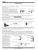
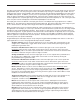
INSTALLATION The AM8/4, because it is so highly integrated, is straightforward to install. The following sections explain the installa tion and wiring, as well as the software setup of the AM8/4. AM8/4 Audio Inputs Unbalanced Line Level Source Balanced Line Level Source Each of the 8 automatic AM8/4 inputs is balanced, and provides 15V phantom power (through 2K ohm feed Input + Input + resistors to the “+” and “-” input connections). Phantom Input Input power is switchable on a per-channel basis.
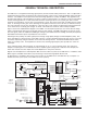
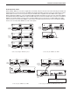
8 Channel Automatic Matrix Mixer Audio Expansion In/Out When multiple AM8/4s are used in an application, their Audio Link ports must be interconnected using the Audio Link In/Out connectors on the rear panel of the AM8/4. The Audio Link In/Out connector is just to the right of the Program mable In/Out connector on the rear panel. An 8 pin mini-DIN cable is supplied with each AM8/4 for this purpose.
When other LecNet devices are used in conjunction with the AM8/4s, the LecNet Expansion ports of these devices must also be interconnected. Refer to the diagrams above for proper interconnections. The LecNet Expansion In and Out pinouts are shown below.
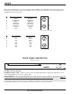
8 Channel Automatic Matrix Mixer REAR PANEL DESCRIPTION EXPANSION O U T PWR IN (PS60) 16.
OPERATING INSTRUCTIONS Since most of the parameters used to set up the AM8/4 are adjusted using the AM8/4 Software Control Panel, the operating instructions include instructions for the use of the software. It’s recommended that you have the software running, either live or in the demo mode, as you read through this section. Power Up When the AM8/4 is powered on, it automatically loads the active setup from Preset 1. Therefore, you should always store the desired power-up setting for the AM8/4 in Preset 1.
8 Channel Automatic Matrix Mixer The input control point labeled “Rear Panel” represents the gain adjustments which can be made from the rear panel programmable inputs. The rear panel gain control is attenuation only, starting at a maximum gain of 0dB. The rear panel input gain controls may be limited in their adjustment range using the Remote Input/Output Level Limits tab on the AM8/4 control panel.
Programmable Output: Used to provide user feedback for certain programmable input functions. A programmable i/o whose function is Programmable Output will be active (i.e. conducting to ground) or inactive (i.e.
8 Channel Automatic Matrix Mixer Enter Input/Output Names... - Allows names to be assigned to the 10 inputs and the 4 outputs of the AM8/4. These names may be up to 15 characters long and are stored in nonvolatile memory in the AM8/4. In addition, the names are stored in any disk files generated with any of the save to disk options above. Inputs or outputs with no assigned names are listed as “No Name”. To change a name, simply click on the desired text box and enter the desired name.
Input Gain Tab The Input Gain tab allows the input gain and Send/React to NOM status to be set for each of the 8 automatic input channels, and the input gain to be set for the two line input channels. Gain - Allows the input gain level to be trimmed between +15dB and -63dB, or Off. The gain shown in the associated box should be added to the preamp gain (set by rear panel dip switches) to calculate the total channel gain.
8 Channel Automatic Matrix Mixer Input Tone Control Tab The Input Tone tab allows the low cut frequency and the high frequency cut or boost to be set for each of the 10 input channels. Low Cut - Sets the low cut corner frequency for each input channel. The low cut filter is a 6dB/octave (i.e. single pole) filter. Frequency choices are 75Hz, 90Hz, 110Hz, 130Hz, 190Hz, 280Hz, 600Hz, and Flat. Short Cut: A left click on the low cut box causes the frequency to be set to “Flat”.
Short Cut: A right mouse click on a crosspoint gain box will set the crosspoint gain to 0dB. Clear Matrix (Clr) Button Clears all matrix crosspoints to the “Off” state. Output Gain Tab The Output Gain tab allows the output gain levels to be set. Gain, Outputs 1 - 4 - Allows the output gain to be set between +15dB and -63dB or “Off”. In addition to the slide control, several “quick gain set” buttons are available for common gains.
8 Channel Automatic Matrix Mixer select different functions. All other parameters are disabled. This eliminates invalid Function/Applies To settings. Each of the available functions is explained below. Hint: If the function (or any associated inputs, outputs, etc.) of a programmable I/O is changed on the control panel, the Apply button will be enabled. The Apply button is located in the lower right hand corner of the Programmable I/O tab.
Minimum Input Gain, if it is programmed for less attenuation than “Off”), and +5VDC corresponds to 0dB. In addition to analog control, this mode can be used to perform input “muting” using a simple toggle switch. To mute input(s), simply connect the toggle switch to connect the programmable input to ground (GND pin). The screen shown below indicates that the function of programmable input 1 is analog input control of inputs 1, 2, 8, and Line 1.
8 Channel Automatic Matrix Mixer “Off”. The gain change resolution is 1dB. In the case of Increase Out 1dB, each contact closure will increment the output(s) gains by 1dB until 0dB is reached. Decrease Out 1dB will decrement the output(s) gains by 1dB until either “Off” or Rear Panel Minimum Output Gain is reached. If the contact closure is pushed and held, it will continue to increment or decrement until it is released or the gain reaches its high or low limit.
Programmable Output - Sets one of programmable I/Os 1-8 to the programmable output mode. Programmable outputs indicate the state of functions controlled by programmable inputs. For example, if programmable I/O 1 is set to Mute output 1, setting programmable I/O 2 to Programmable Output and connecting its Applies To function to Prog Input State 1 means that programmable output 2 will be active when output 1 is unmuted and inactive when output 1 is muted.
8 Channel Automatic Matrix Mixer application. “Off” signifies no lower gain limit. 0dB is the maximum value available for Min Gain, and is equivalent to making rear panel output control inactive. The Gain Preset scroll bar allows a preset gain to be applied at power on to any output(s) controlled by the Increment Output 1dB or Decrement Output 1dB programmable input function. The control panel will always force the Gain Preset to be greater than or equal to the Min Gain.
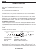
SERIAL CABLE WIRING DIAGRAMS LecNet Device to PC S R T 3.5MM Stereo Plug LecNet Device to AMX or Crestron S R T 9 or 25 Pin Female D-Subminiature 9 Pin Female D-Subminiature 3.
8 Channel Automatic Matrix Mixer SERIAL PORT COMMANDS AVAILABLE All LecNet devices use a modification of the typical one-to-one connection between two RS-232 compatible devices. LecNet devices have both an RS-232 transmitter and receiver section. The transmitter section is “tri-stated”, or placed in a high impedance mode, until the particular device is addressed.
General Device Commands Get Name String - Gets the AM8/4’s “name” string. The first data byte is the length of the name string, and the rest of the data bytes are the device name. Host sends command - 1 (1 hex) Host receives 5 bytes: Byte 1 is the length of the name string (4 for the AM8/4), bytes 2, 3, 4, and 5 are the ASCII values for “AM84” (65,77,56,52) Set Device Address - Sets the AM8/4’s device address and stores the new address in nonvolatile memory.
8 Channel Automatic Matrix Mixer Byte 1: Bits 0 - 6 of the mask (in the low 7 bits of the byte) Byte 2: Bit 7 of the mask (positioned in the LSB of the byte) Byte 3: Bits 8 - 9 of the mask (in the low 2 bits of the byte) Byte 4: 0 A “1” in a bit position will apply the gain in byte 5 to the associated channel, while a “0” in a bit position will not apply the gain to the associated channel.
Matrix Crosspoint Commands Get Crosspoint Gain - Gets the gain associated with a particular matrix crosspoint. Host sends command - 81 (51 hex) Host sends 2 bytes: Byte 1:Input associated with the desired crosspoint. 0 - 10 (0-0A hex), where 0 - 9 corresponds to inputs 1 - 10, and 10 (0A hex) corresponds to the Expansion In. Byte 2: Output associated with the desired crosspoint. 0 – 3, corresponds to outputs 1 - 4. Host receives 1 byte: Crosspoint gain.
8 Channel Automatic Matrix Mixer Set Multiple Input Crosspoint Gains to Multiple Outputs - Sets the crosspoint gain from any combination of the 10 inputs to any combination of the four outputs. Host sends command - 89 (59 hex) Host sends 6 bytes: Bytes 1-4: A 10 bit mask, where each bit position represents one of the 10 inputs. For example, the lowest bit of the mask represents input 1, the next lowest bit input 2, and so on.
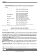
SPECIFICATIONS Inputs: Mic/Line Input Type: Mic/Line Input Impedance: Mic/Line Input Gain Range: Mic/Line Input Gain Settings: EIN, 20-20K Hz: Maximum Input Level: 8 Balanced and RF filtered >2.
8 Channel Automatic Matrix Mixer SERVICE AND REPAIR If your system malfunctions, you should attempt to correct or isolate the trouble before concluding that the equipment needs repair. Make sure you have followed the setup procedure and operating instructions.
LIMITED YEAR WARRANTY LIMITED ONE ONE YEAR WARRANTY The equipment is warranted for one year from date of purchase against defects in materials or workmanship provided it was purchased from an authorized dealer. This warranty does not cover equipment which has been abused or damaged by careless handling or shipping. This warranty does not apply to used or demonstrator equipment. Should any defect develop, Lectrosonics, Inc.