USER MANUAL
Information in this manual is subject to change without notice and does not represent a commitment on the part of Applied Acoustics Systems DVM Inc. The software described in this manual is furnished under a license agreement. The software may be used only in accordance of the terms of this license agreement. It is against the law to copy this software on any medium except as specifically allowed in the license agreement.
Contents 1 2 Introduction 7 1.1 System Requirements . . . . . . . . . . . . . . . . . . . . . . . . . . . . . . . . . 7 1.2 Installation and Authorization . . . . . . . . . . . . . . . . . . . . . . . . . . . . 8 1.3 Getting Started . . . . . . . . . . . . . . . . . . . . . . . . . . . . . . . . . . . . 8 1.3.1 Using Chromaphone 3 in Standalone Mode . . . . . . . . . . . . . . . . . 8 1.3.2 Exploring the Factory Sounds . . . . . . . . . . . . . . . . . . . . . . . . 9 1.3.
CONTENTS 5 The Editor View 29 5.1 General Functioning of the Interface . . . . . . . . . . . . . . . . . . . . . . . . . 29 5.1.1 Knobs . . . . . . . . . . . . . . . . . . . . . . . . . . . . . . . . . . . . . 29 5.1.2 Switches . . . . . . . . . . . . . . . . . . . . . . . . . . . . . . . . . . . 29 5.1.3 Drop-down Menus . . . . . . . . . . . . . . . . . . . . . . . . . . . . . . 29 5.1.4 Modulation Signals . . . . . . . . . . . . . . . . . . . . . . . . . . . . . . 29 5.1.
CONTENTS 6 7 8 5 5.4.7 Phaser . . . . . . . . . . . . . . . . . . . . . . . . . . . . . . . . . . . . . 57 5.4.8 Wah Wah . . . . . . . . . . . . . . . . . . . . . . . . . . . . . . . . . . . 59 5.4.9 Notch Filter . . . . . . . . . . . . . . . . . . . . . . . . . . . . . . . . . . 59 5.4.10 Guitar Amplifier . . . . . . . . . . . . . . . . . . . . . . . . . . . . . . . 60 5.4.11 Tremolo . . . . . . . . . . . . . . . . . . . . . . . . . . . . . . . . . . . . 61 5.4.12 Reverb . . . . . . . . .
CONTENTS 9 8.2.1 Selecting a MIDI Device . . . . . . . . . . . . . . . . . . . . . . . . . . . 72 8.2.2 MIDI Channel Volume and Expression Controller . . . . . . . . . . . . . . 72 8.2.3 Creating MIDI Control Assignments . . . . . . . . . . . . . . . . . . . . . 72 8.2.4 Creating a default MIDI Assigment Map . . . . . . . . . . . . . . . . . . 73 8.2.5 MIDI Program Change . . . . . . . . . . . . . . . . . . . . . . . . . . . . 73 8.2.6 Pitch bend . . . . . . . . . . . . . . . . . . . .
Introduction 1 Introduction Chromaphone is a synthesizer based on acoustic resonators. Combinations of resonators are used to create drums, percussion, string and hybrid synth-like instruments. Membranes, bars, marimbas, plates, strings, and tubes form pairs that are excited by a mallet and a flexible noise source.
Introduction 1.2 Installation and Authorization Installation and authorization of Chromaphone 3 is quick and easy. For the installation of our different products we use so-called custom installers which include both the program itself and your licence information. Installation and authorization can therefore be carried out automatically in a single step and from a single file when your computer is online.
1.3 Getting Started Audio and MIDI Configuration Audio and MIDI configuration tools are available by clicking on the Audio MIDI Setup button located in the Settings view which is accessed by clicking on the Settings tab at the top of the interface. The Setup dialog first allows you to select an audio output device from those available on your computer. Multi-channel interfaces will have their outputs listed as stereo pairs. On Windows, the audio output list is organized by driver type.
1.4 Introduction Getting Help AAS technical support representatives are on hand from Monday to Friday, 9am to 6pm EST. Whether you have a question on Chromaphone 3, or need a hand getting it up and running as a plug-in in your favorite sequencer, we are here to help. Contact us by phone or email at: • North America Toll Free: 1-888-441-8277 • Worldwide: 1-514-871-8100 • Email: support@applied-acoustics.
Architecture of Chromaphone 3 2 11 Architecture of Chromaphone 3 Chromaphone is synthesizer built around the combination of acoustic resonators. The resulting instruments are played using a mallet or the signal from a noise source. It is very simple yet the range of sounds it is capable of is surprisingly wide, from realistic reproductions of acoustic percussion instruments to creative and innovative tones simply not possible with traditional synthesizers. 2.
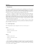
Architecture of Chromaphone 3 Figure 2: Signal flow of Chromaphone. Resonators in coupling mode. 2.2 Multimbral Architecture Chromaphone 3 is a multitimbral synthesizer which can play two different timbres simultaneously either in layered or split keyboard mode. The general architecture of the synthesizer is shown in Figure 3 and consists of a MIDI routing module, two independent Chromaphone engines in parallel, a mixer, and a multi effects module.
2.3 Interface 13 The center element of this section is a small sound browser which displays the currently loaded pack and sound. One can navigate through the pack by using the left and right arrows which appear to the right of the sound name. The computer keyboard arrows can also be used to navigate through sounds but this control must first be selected by clicking on the arrows or the sound name. The arrows then become surrounded by an orange line.
Architecture of Chromaphone 3 Figure 5: The Home view. out. A complete description of the sound browser is the subject of Chapter 4. 2.3.3 The Editor View Clicking on the Editor tab gives access to the synthesis engine itself. The multitimbral architecture of Chromaphone 3 includes two identical instances of the synthesis engine in parallel, each represented by a different color and corresponding to one layer or sound.
2.3 Interface 15 Figure 6: The Browser view. Figure 7: The Editor view.
Architecture of Chromaphone 3 The Layer Mixer The layer mixer, shown in Figure 8, includes general controls which can be applied to each layer. It is where the output level of each layer can be monitored and adjusted using the different level meters and Gain knobs. Each layer can be named using a label. In order to edit a label, click on it and type on the computer keyboard. Once a name has been entered, hit the Return key or click outside the label in order to deselect this region.
2.3 Interface 17 Figure 9: The Modes section. Figure 10: The Synth section. The Effects Section The Effects section proposes a multi-effects module comprising five effects in series. The effect list includes an EQ, Compressor, Reverb, Delay, Distortion, Chorus, Flanger, Phaser, Wah Wah, Auto Wah, Guitar Amplifier, Tremolo, and a Notch filter. The position of a module in the signal path can be changed by click-holding on the handle to the left of the module and moving it to the desired position.
Architecture of Chromaphone 3 Figure 11: The Effects section. 2.3.4 The Settings View The Settings view is accessed by clicking on the Settings tab. This is where general parameters and options for, display size, polyphony, general tuning, MIDI assigments and MIDI configuration are adjusted. The different setting options will be described in details in Chapter 6. Figure 12: The Settings view.
The Home View 3 19 The Home View This is the main view for auditioning sounds and playing. The first elements of the view are displays with a representation of the resonator combination used in each layer of the current sound. The output level for each layer can be adjusted using the knob located in the lower right corner of the displays. In the lower part of this view are four macro controls allowing one to easily adjust high-level qualities or characteristics of the sound being played and modify it.
The Home View mapped parameter is kept fixed. Note that the Modulation knob only varies between 0 and 1 since it is assumed that amplitude modulation or vibrato can only be added to a sound. These four macro parameters can be assigned to external MIDI controllers for increased expressivity and playability. The mapping between a macro and an external controller is carried out in the Settings view as described in Chapter 7 or by clicking on the label located just below the macro knob.
The Browser View 4 21 The Browser View In the context of Chromaphone 3, a sound is a preset for the parameters of the entire synthesizer. Sounds are created by combining layers, each corresponding to a different instance of the synthesis engine. In this section we first review the browsing of sounds and their organization into Sound Packs. We then review the so-called Layer Browser which is used for the creation of new sounds.
The Browser View the original version. This is useful when deciding if a sound should be replaced by a new version. Note that once the button has been switched on all further modifications on a sound are blocked. In order to allow edition again, the command must be switched off. A new copy of a sound is saved by using the Save As command which is activated by clicking on the corresponding button which opens the Save Sound pop-up window. The name of the sound is entered at the top of this window.
4.3 The Sound Browser 23 Figure 15: Browsing by sound pack. Figure 16: Browsing the entire library by sounds. enters a name for the pack and clicks on the Create button.
The Browser View Figure 17: Browsing the library by sound category. Figure 18: Browsing the library by creator. pack list. Packs and the information corresponding to their sounds are stored as files in a Packs folder on your computer hard disk. In order to access this Packs folder, click on the Show Packs Folder command in the same menu.
4.3 The Sound Browser 25 opens a Finder window. All the pack file names follow the same format which consists of the pack name followed by the CP-3 Pack extension. These files can be used for backups or to exchange sounds with other users. Different commands can be applied to a user pack once it has been selected. These are revealed by clicking on the ellipsis icon located to the right of the pack name at the top of the browser. A pack can be renamed by choosing the Rename command.
The Browser View sound. The destination pack is then selected by clicking on its image and the sound copied by using the Paste command. A sound can also be moved to another pack by selecting it and then dragging and dropping it onto the image of a pack. Be careful however as this command, unlike the copy command, copies the selected sound to the destination pack but also deletes it from the original pack. This is only true however for sounds from user packs.
4.6 The Layer Browser 27 Figure 19: The layer browser. Layer presets from library sounds are browsed by pack. The list of layers included in the selected pack are displayed on the right of the pack list. Layers are organised in sound categories and are listed using the name of the sound they come from and their associated slot (layer A or layer B). One can jump from one sound category to another by using the category drop-down menu at the top of the pack list.
4.7 The Browser View Importing Sounds from Previous versions of Chromaphone Chromaphone 3 includes a converter that allows one to import sounds from Chromaphone 2. The conversion operation simply involves copying an Chromaphone 2 pack file into the Chromaphone 3 sound pack folder. The conversion operation is then triggered automatically when Chromaphone detects a pack from a previous version.
The Editor View 5 29 The Editor View This section can be used as a reference for the controls appearing on the different modules of the synthesis engine of Chromaphone 3. These modules are accessed from the Editor view which is displayed by clicking on the Editor tab located at the top of the interface. This synthesizer is two-voice multitimbral and is therefore based on two instances of the synthesis engine.
The Editor View sources include the MIDI pitch and velocity, signals (Key and Vel labels), the signal from the Noise Envelope and LFO modules (Env and LFO labels), as well as a random signal (RDM label). A modulation can be viewed as the variation of a parameter around its current value controlled by a modulation signal. The different modulation controls act as gain parameters which multiply the modulation signal by a certain factor.
5.1 General Functioning of the Interface 31 notes (16 quarter notes) to a thirty-second note (1/8 of a quarter note) where the duration of the whole note is determined by the host sequencer clock. The effect can also be synced to a triplet or dotted note. To adjust this parameter, click on the Sync Rate button and choose a rate value from the drop-down menu.
5.2 The Editor View The Modes Section The Modes section is where the main performance oriented modules are located. It is accessed by clicking on the Modes tab of each layer. 5.2.1 The Clock Module This module is used to control the tempo of the different effects of the Effects section as well as that of the LFO and Arpeggiator modules when their respective sync button is switched on. When Chromaphone 3 is launched in standalone mode the clock tempo, in bpm, is set by using the Rate knob.
5.2 The Modes Section 33 voices can be desynchronized by adding a small time lag between their triggering with the Delay knob. There is no delay when the knob is in its leftmost position and it increases (units in ms) as it is turned clockwise. 5.2.4 The Macros Module The Macros module includes four different macros associated with different high-level qualities or characteristics of the sound.
The Editor View leftmost position and 100 % in their rightmost position with a value of 0 % when in their center position. This value represents the maximum possible percentage of variation of the destination parameter, in terms of its range, around its current value. A value of 100 % therefore means that the destination parameter can vary over its full range while a value of zero means that its value will remain fixed.
5.2 The Modes Section 35 the mapped external controller. An orange line is displayed around the Amount knobs in order to indicate the total amount of the modulation signal applied to destination parameters. Mapping of Macro modules to external MIDI controllers is described in Chapter 7. One may wonder why there is an Amount knob both on the Home view and Modes section of the Editor view.
The Editor View Arpeggio Patterns The arpeggio pattern is set by the combination of the value of the Range, Span and Order controls. The Range control is used to select the number of octaves across which the pattern is repeated. When the range is set to 0, there is no transposition and only the notes currently depressed are played.
5.3 The Synth Section 37 Latch mode The Arpeggiator module is toggled in latch mode by clicking the Latch button to its on position. In this mode, the Arpeggiator keeps playing its pattern when the notes on the keyboard are released and until a new chord is played. 5.2.7 Virtual Keyboard The lower part of each view includes a virtual keyboard. The keyboard covers seven octaves and notes are activated by clicking on the keyboard.
The Editor View air which will propagate to our ears as sound waves. Mathematically, a complex vibrational motion can be decomposed into elementary motion patterns called the normal modes of the object. Under a normal mode, all the parts of the structure move in phase and at the same frequency in a sinusoidal motion.
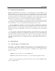
5.3 The Synth Section 39 Figure 22: Contour plot corresponding to normal mode [1,1] and [3,2] of a plate. But this is not all, we can distinguish different types of objects, such as a vibrating plate and a beam, but also two objects of the same type but made out of different material. For example a metal plate will sound brighter and have a longer decay than a wooden plate.
The Editor View The coupling of objects results in a bidirectional transfer of energy between the objects. In physical terms, the amount of exchange is determined by the relative value of the mechanical impedance of the different objects. The impedance is a notion which measures how much an object opposes motion when subjected to a force. It is a frequency domain function as the response of an object can vary greatly with frequency.
5.3 5.3.2 The Synth Section 41 The Mixer Module The two Chromaphone resonators can be excited by a mallet and a noise source. The Mixer module is used to adjust the amplitude of both of these sources. The Mallet knob is used to adjust the amplitude of the force impact from the mallet while the Noise knob controls the amplitude of the noise source. Both of these parameter can be modulated with pitch and MIDI velocity. The noise source can also be modulated with the LFO module.
The Editor View signal and one only hears the impact noise. Turning this knob clockwise gradually increases the amount of noise. The frequency content of the noise can be adjusted with the help of the Color control. Turning this knob clockwise increases the cut-off frequency of a high-pass filter. 5.3.4 The Noise Module The Noise module is an alternate way to excite the resonator.
5.3 The Synth Section 43 and one can clearly hear individual random noise samples which may sound like individual particles hitting the surface of the resonators. Increasing the noise density by turning the knob clockwise increases the number of clicks generated in a given interval of time until the output starts to become continuous. This parameter can be used to produce interesting effects by exciting the resonators randomly.
The Editor View • Drumhead: circular membrane, • Membrane: rectangular membrane, • Open Tube: a cylindrical tube with both ends open allowing one to obtain the complete harmonic series (even and odd harmonics), • Closed Tube: a cylindrical tube with one end closed allowing one to obtain only odd harmonics, • Manual: In this mode, one can create a custom resonator by selecting up to four partials (see Quality control). The rank of each partial is fixed using the Partial 1 to Partial 4 selectors.
5.3 The Synth Section 45 The decay time of the partials of the object is determined by the Decay control. This parameter can be modulated as a function of the note played on the keyboard and its MIDI velocity using the Key and Vel modulation parameters respectively. Note that in the case of a Tube object, the decay time of the sound is also affected by the Radius parameter. In that case, the total decay time will be determined by the cumulative effect of the Decay and Radius parameters.
The Editor View thereby removing more and more low frequency content in the sound. The Radius parameter replaces the Material control when a Tube object is selected. In fact, standing waves in a tube do not result from the vibrations of the walls of the tube but rather by vibrations of the air column inside the tube. The material of the tube is therefore not a relevant parameter in that case.
5.3 The Synth Section 47 resonator A and hence the frequency of its fundamental and partials depending on the settings of resonator B. In other words, one starts to hear resonator B more and more in the final sound. The amount of coupling or balance (in the case where they are in parallel mode) between the resonators, can be modulated with the pitch of the note played with the Key control. 5.3.
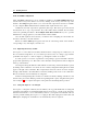
The Editor View Figure 24: ADSR Response curve. Figure 25: AHD envelope response curve.
5.4 5.3.7 The Effects Section 49 The LFO Module The LFO module is used as a modulation source for the Noise source module. The waveform of the LFO is selected with the Shape drop-down menu on the top of the module. The possible values are Sine, Triangular, Square, Random and Random Ramp. The shape of the triangular and square waveform can be varied using the Width parameter.
The Editor View The Effects modules allows one to process and shape the signal. The type of each module can be set by using the drop-down menu located to the left of each module. They are turned on or off by using the power button located just before the name of the effect. The effect list includes an EQ, Compressor, Reverb, Delay, Distortion, Chorus, Flanger, Phaser, Wah Wah, Auto Wah, Guitar Amplifier, Tremolo, and a Notch filter.
5.4 The Effects Section 51 The Equalizer module features two peak filters, labeled LMF and HMF, allowing to shape the signal in two frequency bands as illustrated in Figure 27. The filters apply a gain factor to frequency components in a band located around the cutoff frequency of the filters. This cutoff frequency is adjusted using the Freq knob and can vary between 100 Hz and 10 kHz. The gain factor applied a the cutoff frequency is controlled by the Gain knob and can vary in a ±15 dB range.
The Editor View The amount of compression applied to the part of the signal exceeding the threshold value depends on the Ratio parameter which varies between value of 1:1 and 1:16. This parameter represents the ratio, in dB, between the portion of the output signal from the compressor above the threshold value and the portion of its input signal also exceeding the threshold value. As one might expect, increasing the ratio also increases the amount of compression applied to the signal.
5.4 The Effects Section 53 The Pan knob is used to balance the input signal between the left and right channels. In its leftmost position, signal will only be fed into the left delay line and one will hear clearly defined echo first from the left channel and then from the right channel and so on. In its rightmost position, the behavior will be similar but with the first echo coming from the right channel.
5.4.5 The Editor View Chorus The chorus effect is used to make a source sound like many similar sources played in unison. It simulates the slight variations in timing and pitch of different performers executing the same part. The effect is obtained by mixing the original signal with delayed version obtained from the output of delay lines as shown in Figure 28.
5.4 The Effects Section 55 and right output signal on each channel. In other words the signal is the same on both channels. In its rightmost position, there is complete separation between the channels, the left output from the chorus is only sent to the left channel while the right output of the chorus is only sent to the right channel. Finally, the Mix knob allows one to mix the dry and wet signals.
The Editor View Figure 30: Frequency response of a Flanger module. Effect of the length of the delay line. by the amount of wet signal re-injected into the feedback loop as shown in Figure 32. Increasing the feedback enhances frequency components least affected by the delay line and located at even harmonic intervals of the fundamental frequency. As the feedback is increased, these peaks become sharper resulting in an apparent change in the pitch of the signal.
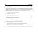
5.4 The Effects Section 57 Figure 32: Effect of the amount of feedback on the frequency response of a Flanger module. sent to the output. 5.4.7 Phaser The Phaser module implements the effect known as phasing which colors a signal by removing frequency bands from its spectrum. The effect is obtained by changing the phase of the frequency components of a signal using an all-pass filter and adding this new signal to the original one. The algorithm implemented in this module is shown in Figure 33.
The Editor View Figure 33: Phaser algorithm. Figure 34: Frequency response of a Phaser module. Effect of the mix between wet and dry signal on the frequency response. Tuning The location of the first notch in the frequency response of the module is adjusted with the Frequency knob This frequency can be modulated by an amount controlled with the Depth knob.
5.4 The Effects Section 59 wet signal is sent to the output. 5.4.8 Wah Wah The Multi-Effect module includes 2 different types of Wah effects: wah wah, and auto wah. These effects are used to enhance a frequency band around a varying center frequency using a bandpass filter. In the wah wah effect, the center frequency of the bandpass filter varies at a rate fixed by the user.
The Editor View The Freq knobs is used to control the central frequency of the filter. Turning this knob clockwise increases the center frequency. The Depth knob controls the excursion of the center frequency of the filter around its center frequency. Turning this knob clockwise increases the excursion of the center frequency. Finally, the Rate knob controls the frequency or rate of the modulation of the center frequency of the filter. Turning this knob clockwise increases the rate of the modulation.
5.4 The Effects Section 61 sound while channel two is well-suited when strong distortion is required. The Drive knob is used to adjust the amount of distortion in the sound. The sound becomes more and more distorted as the knob is turned clockwise. The Mid knob is used to set the amount of mid-range frequencies in the sound. In its middle position, the sound is not modified, mids are cut or boosted by up to ±12 dB by turning this knob to the left or right.
5.4.12 The Editor View Reverb The Reverb module is used to recreate the effect of reflections of sound on the walls of a room or hall. These reflections add space to the sound and make it warmer, deeper, as well as more realistic since we always listen to instruments in a room and thus with a room effect. This module is located at the very end of the effects chain in the signal flow.
5.4 The Effects Section 63 in the high frequencies the reverberation time is shorter for these frequencies. These parameters are adjusted with the Low and High knobs respectively. Another parameter which affects the response of a room is its geometry; the more complex the geometry of a room, the more reflexion are observed per unit of time. This quantity is known as the time density and can be set trough the Diffusion knob.
6 The Settings View The Settings View 6.1 Settings Clicking on the Settings tab in the top of the interface opens the Settings view, shown in Figure 37, which is where some general parameters of the synthesizer, such as tuning, number of polyphony voices, pitch bend range, and external macro modules assignments, are fixed. The value of these parameter is not saved in a sound preset and therefore apply to all sounds. In other words, these parameters do not vary when new sounds are loaded.
6.1 Settings 65 the control and selecting the desired number of voices. In general, a higher number of voices is desirable but keep in mind that the CPU load is proportional to the number of voices used. 6.1.3 Master Tuning Musical instruments are usually tuned based on a fixed reference, such as A440, and a temperament. The reference is a note whose frequency is fixed, for example 440 Hz for the A above the middle C of the keyboard in the case of A440.
The Settings View appearing when clicking on the drop-down menus of this section for each of the Macros module. The Learn command can also be used to assign a controller. When one of the Learn buttons is switched on, the corresponding modulator will be assigned to the first continuous controller from which a message is received. Note that when the None option is chosen, the corresponding Modulator will not respond to any controller. For more information on the Macros modules, please refer to section 5.
6.1 Settings 67 Pitch Bend Chromaphone 3 reacts to the MIDI pitch bend signal when this option is activated. By default, the pitch bend is controlled by the pitch bend wheel but this can be changed by using the drop down menu appearing in this section. A Learn command is available to assign a controller automatically. In order to adjust the range of the pitch bend, use the Pitch Bend Range drop-down menu. The different options are listed in number of semi-tones.
6.1.9 The Settings View Saving Settings Once changes are made to any parameter in the settings window, they are applied to the synthesizer regardless of the sound played. In plug-in mode, the value of these settings are automatically saved with the DAW project. In order to save the settings, one needs to use the Save Current as Default button, under Settings. The settings values last saved will be used as the default values when a new instance of the program is started in plugin mode.
Utility Section 7 69 Utility Section The utility section is located at the top of the Chromaphone interface and it includes important parameters and monitoring tools. For information on the selection of sounds and sound packs, as well as the Save and Save As commands, please refer to Chapter 4 7.1 The MIDI LED The MIDI LED is located on the left of the utility section just below the Chromaphone logo. The LED blinks when the synthesizer receives MIDI signal.
Utility Section important to make sure that the amplitude of the signal remains within values that ensure that no distortion is introduced in the signal at the output. The 0 dB mark on the level meter has been adjusted to correspond to -20 dBFS (full scale). This means that at that level, the signal is -20 dB below the maximum allowed value. This 0 dB level mark should typically correspond to playing at mezzo forte (moderately loud) level.
Audio and MIDI Settings 8 71 Audio and MIDI Settings This chapter explains how to select and configure Audio and MIDI devices used by Chromaphone 3. Audio and MIDI configuration tools are accessed from the Settings view which is accessed by clicking on the Settings tab in the top of the interface. Note that in plug-in mode the audio and MIDI inputs, sampling rate, and buffer size are set by the host sequencer. 8.1 8.1.
Audio and MIDI Settings Depending on your machine you should choose, for a given sampling frequency, the smallest buffer size that allows you to keep real-time for a reasonable number of voices of polyphony. 8.2 MIDI Configuration 8.2.1 Selecting a MIDI Device The list of available MIDI inputs appears at the bottom of the Audio Setup dialog.
8.2 MIDI Configuration 73 • Move a knob or slider on your MIDI controller (this can be a keyboard, a knob box, or any device that sends MIDI). This will link the control of the Chromaphone 3 to the MIDI controller you just moved. To deactivate a MIDI assignment, simply right-click/Control-click on the corresponding control on the Chromaphone 3 interface and select the Forget MIDI Assignment command. Note that MIDI assignments are not saved with sound presets.
Audio and MIDI Settings Pitch bend can quickly be disabled or enabled for each layer from the Layer Settings window which is opened by clicking on the ellipsis icon next to a layer label and choosing the Layer Settings command. 8.2.7 Modulation Wheel Chromaphone 3 responds to the signal from the modulation wheel of MIDI keyboards (continuous controller number 1). The first macro module is usually mapped to this controller. For more information on the Macros modules, please refer to section 5.2.4. 8.
Using Chromaphone 3 as a Plug-In 9 75 Using Chromaphone 3 as a Plug-In Chromaphone 3 is available in VST2, VST3, AAX and Audio Units formats and integrates seamlessly into the industry’s most popular multi-track recording and sequencing environments as a virtual instrument plug-in. Chromaphone 3 works as any other plug-in in these environments so we recommend that you refer to your sequencer documentation in case you have problems running it as a plug-in.
9.6 Using Chromaphone 3 as a Plug-In Performance Using a plug-in in a host sequencer requires CPU processing for both applications. The load on the CPU is even higher when multiple instances of a plug-in or numerous different plug-ins are used. To decrease CPU usage, remember that you can use the freeze or bounce to track functions of the host sequencer in order to render to audio the part played by a plug-in instead of recalculating it every time it is played.
License Agreement 10 77 License Agreement IMPORTANT! CAREFULLY READ ALL THE TERMS AND CONDITIONS OF THIS AGREEMENT BEFORE OPENING THIS PACKAGE. OPENING THIS PACKAGE INDICATES YOUR ACCEPTANCE OF THESE TERMS AND CONDITIONS. IF YOU DO NOT AGREE WITH THE TERMS AND CONDITIONS OF THIS AGREEMENT, PROMPTLY RETURN THE UNOPENED PACKAGE AND ALL COMPONENTS THERETO TO THE PARTY FROM WHOM IT WAS ACQUIRED, FOR A FULL REFUND OF ANY CONSIDERATION PAID.
License Agreement 5. LIMITATION OF LIABILITY.
License Agreement 79 rendered inoperative but the remaining provisions shall continue in full force and effect. 9. ENTIRE AGREEMENT.
Index about, 70 adsr, 47 ahd, 47 architecture, 11, 12 arpeggiator, 35 latch, 37 looping, 36 pattern, 36 rate, 36 rhythmic pattern, 36 synchronization, 36 arrows computer keyboard, 21 sound browser, 21 audio, 71 configuration, 9, 71 device, 67, 71 latency, 71 auto-wah, 17, 49, 59 backup, 25, 26 beam, 43 browser, 21 buffer size, 9, 71 cabinet, 60 chorus, 17, 49, 54 mono, 54 stereo, 54 clock, 30, 32 closed tube, 43 coarse, 29 compare, 22, 69 compressor, 17, 49, 51 contact, 10 control assigments, 66 cpu load, 6
INDEX latency, 71 layer, 26 browser, 26 gain, 16 load, 27 mixer, 16 mute, 16 pan, 16 pitch bend, 73 save, 27 solo, 16 tuning, 16 level meter, 69 lfo, 49 rate, 49 synchronization, 30 wave shape, 49 limiter, 69 macro, 13, 19, 33 macro:effect, 33 macro:envelop, 33 macro:modulation, 33 macro:timbre, 33 macros, 13, 19 mallet, 41 manual, 70 manual mode, 43 marimba, 43 master clock, 32 master effects, 14 master tuning, 65 master volume, 16, 69 membrane, 43 micro-tuning, 65 MIDI, 71 assignment map, 73 cc, 65 chann
noise source, 42 notch filter, 17, 49, 59 note priority, 66 numerical displays, 29 open tube, 43 output gain, 63 overdrive, 53 pack, 21, 22 AAS, 21 backup, 22, 26 commands, 22 create, 22 creating, 22 delete, 22 duplicate, 22 exchange, 22 factory, 21 new, 22 read-only, 21 rename, 22 sharing, 26 show files, 25 user, 21 parameters, 29 peak, 69 phaser, 17, 49, 57 pitch bend, 73 direction, 67 range, 67 plate, 43 plug-in, 9 audio configuration, 75 automation, 75 formats, 75 MIDI configuration, 75 MIDI program
INDEX select all, 25 sharing, 26 tone quality, 21 trash, 26 user, 22 sound browser, 22 speaker, 60 split keyboard, 37 spring reverb, 60 standalone, 8 start-up, 8 string, 43 studio mix, 63 switches, 29 synchronization, 30, 32 synchronization to a host, 32 synth section, 16, 37 system requirements, 7 timbre, 13, 19, 33 transpose, 65 tremolo, 17, 49, 61 tube, 43 tuning, 65 utility section, 69 vibrato, 16, 35 virtual keyboard, 37 voices, 64 volume, 69 VU meter, 69 wah wah, 17, 49, 59 warm tube, 53 83