
User's Manual
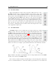
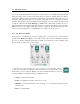
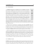
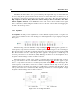
Table Of Contents

42 The Editor View
signal and one only hears the impact noise. Turning this knob clockwise gradually increases the
amount of noise. The frequency content of the noise can be adjusted with the help of the Color
control. Turning this knob clockwise increases the cut-off frequency of a high-pass filter.
5.3.4 The Noise Module
The Noise module is an alternate way to excite the resonator. This module can be
used to add noise to the impact signals from the Mallet module but, with its associated
envelope generator, it also allows one to produce long excitation signals, very different
from the impact-like signals from the Mallet module, and add sustain to the sound.
The source of this module is a white noise generator whose output can be filtered
using the different filters available from the Filter drop-down list at the top of the
module. Available filter types are: resonant low-pass, resonant high-pass, band-pass,
and low-pass and high-pass in cascade allowing for a flat response in the pass band.
There is also a graphic mode allowing for precise multi-band shaping of the noise
source.
The amplitude of the noise source is controlled using the Noise knob from the
Mixer module and the envelope signal from the Envelope module. This parameter can further be
modulated with the pitch or velocity signal from the keyboard or with the output from the LFO
module.
The Frequency control is used to adjust the cut-off or center frequency depending on the type
of filter used to shape the noise source. This parameter can be modulated with the the pitch or
velocity signal from the keyboard or with the output from the Noise Envelope or LFO module.
The third control for this module has different values depending on the type of filtering applied
to the noise source. When a resonant filter is chosen, the label for this parameter is Q and the
parameter controls the resonance or quality factor of the filter. In the case where a combination of
low-pass and high-pass filter is chosen, the label is Width and the parameter controls the width of
the pass-band of the resulting filter.
In the case when the Graphic option is chosen in Filter list, the noise source is shaped by a
filter bank. The Frequency and Q knobs are replaced by ten sliders each one being associated with
a specific frequency band. The different bands are controlled by a band-pass filter except for the
first and last bands which are controlled by a low and high pass filter respectively. The amplitude
of each band can be adjusted from −∞ to zero dB. When all the sliders are in their rightmost or
0 dB position, the spectrum of the noise source is flat. Moving any slider to the left decreases the
amplitude of the noise source in the corresponding frequency band until it is completely removed
when the slider reaches its leftmost position. Another way to work with these filters is to put all
the sliders in their leftmost position, equivalent to switching off the noise source, and then adding
noise in the desired frequency bands.
The last parameter of the module is called Density and it is used to control the rate at which
random samples are fired by the module. When this control is in its left position, the density is low