
User's Manual
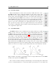
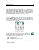
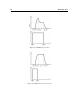
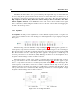
Table Of Contents

5.4 The Effects Section 49
5.3.7 The LFO Module
The LFO module is used as a modulation source for the Noise source module.
The waveform of the LFO is selected with the Shape drop-down menu on the top of
the module. The possible values are Sine, Triangular, Square, Random and Random
Ramp. The shape of the triangular and square waveform can be varied using the Width
parameter. In the case of the triangular wave, the waveform is thus varied gradually
from a triangular shape in the middle position to a sawtooth shape starting at its lowest
value and going up when the knob is turned to its leftmost position to a sawtooth
starting from its maximum point and going down when the knob is fully turned to the
right. In the case where the square wave is selected, the waveform is square when
the knob is in its center position and is transformed gradually to a smaller and smaller
pulse as the knob is moved anti-clockwise and to a an increasingly rectangular wave
when moving the knob clockwise from its center position. When the waveform is set
to Random, the LFO module outputs random values at the rate determined by the Sync control or
the Rate knob. In this case, the output value from the LFO module remains constant until a new
random value is introduced. The Random Ramp mode reacts almost like the preceding mode except
that the LFO module ramps up or down between successive random values instead of switching
instantly to the new value.
There are two ways to adjust the rate, or frequency, of the output of the LFO module. If the
Sync control is in its off position, the rate is fixed with the Rate knob. When the Sync control is on,
the frequency of the oscillator is fixed relative to the frequency (tempo) of the host sequencer and
the value set by the Sync control. Sync values range from 16 quarter notes (4 whole notes) to 1/8
of a quarter note (a thirty-second note) where the duration of the whole note is determined by the
host sequencer. The LFO module can also be synced to a triplet (t) or a dotted note (d).
The Delay control allows one to insert a delay between the moment a note is played and the
triggering of the LFO module. Finally the Offset parameter determines the point in the waveform
from which the LFO module is triggered. In its left position, there is no offset and the waveform
starts with with a zero phase. Increasing the Offset parameter moves the starting point later in
the waveform. For example, if a sine wave is selected and the offset adjusted to a value of 25%,
the starting point will correspond to a quarter of a period and therefore to a positive peak of the
waveform and the signal will start decreasing. A value of 75% would correspond to three quarter
of a period and therefore a negative peak and the signal value would then start increasing.
5.4 The Effects Section
The Effects section is displayed by clicking on the Effects tabs in the layer mixer section and is
based around a multi-effects module. Note that there is a multi-effects module at the output of each
layer and one at the output of the synthesizer (labelled Master Effects) located after the layer mixer
in signal flow. The individual effects modules are identical in each of these multi-effects modules.