
User manual

38 Parameters
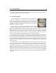
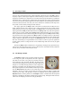
4.9 The Distortion module
The Distortion module implements a simple distortion effect, such
as that found in electric guitar distortion pedals for example. Different
distortion algorithms, ranging from mellow to metal, can be selected
from the Type drop-down menu.
The Drive knob is a gain control used to adjust the level of the
signal at the input of the Distortion module and hence the amount of
saturation introduced in the signal. The color of the signal after the distortion algorithm has been
applied can be adjusted using the Tone knob. In its leftmost position, high frequencies will be
attenuated in the signal while in its rightmost position low frequencies will be filtered out from the
signal. In its center position, the signal will be left unchanged. Note that this control can be set to
its middle position by clicking on the small LED above the knob. Finally, the Level knob is used to
control the amplitude of the signal at the output of the Distortion module.
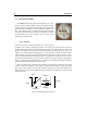
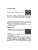
4.10 The EQ module
The EQ module provides equalization over the low, mid, and high
frequency bands. This module is located after the Distortion module
in the signal chain and is composed of a low shelf filter, a bandpass
filter, and a high shelf filter in series.
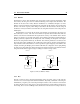
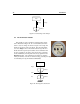
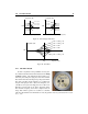
The functioning of the low shelf filter is illustrated in Figure 23.
The filter applies a gain factor to frequency components located be-
low a cutoff frequency while leaving those above unchanged. The
cutoff frequency of the filter is adjusted using the Freq knob and the
gain amount is controlled with the Gain knob.
The high frequency content of the signal is controlled with a high shelf filter that works in
the opposite manner as the low shelf filter as illustrated in Figure 23. The filter will multiply a
gain factor to components located above a cutoff frequency while leaving those below unchanged.
Again use the Freq and Gain knobs to adjust the cutoff frequency and gain of the filter.
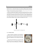
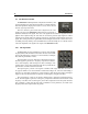
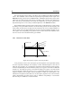
The mid frequency content of the signal is adjusted using a peak filter as illustrated in Fig-
ure 24. The filter applies a gain factor to frequency components in a band located around the cutoff
frequency of the filter. The cutoff frequency of the filter is adjusted with the Freq knob while the
gain coefficient is varied with the Gain knob. In addition to these parameters, the width of the
frequency band can be adjusted with the Q knob.