USER MANUAL
Information in this manual is subject to change without notice and does not represent a commitment on the part of Applied Acoustics Systems DVM Inc. The software described in this manual is furnished under a license agreement. The software may be used only in accordance of the terms of this license agreement. It is against the law to copy this software on any medium except as specifically allowed in the license agreement.
Contents 1 2 3 4 Introduction 8 1.1 System requirements . . . . . . . . . . . . . . . . . . . . . . . . . . . . . . . . . 9 1.2 Installation . . . . . . . . . . . . . . . . . . . . . . . . . . . . . . . . . . . . . . 9 1.3 Registration . . . . . . . . . . . . . . . . . . . . . . . . . . . . . . . . . . . . . . 10 1.4 Getting started . . . . . . . . . . . . . . . . . . . . . . . . . . . . . . . . . . . . . 11 1.5 Using the Tassman as a Plug-in . . . . . . . . . . . . . . . . . . . . . . .
CONTENTS 5 6 The Browser 60 5.1 The Instruments folder . . . . . . . . . . . . . . . . . . . . . . . . . . . . . . . . 60 5.2 The Performances folder . . . . . . . . . . . . . . . . . . . . . . . . . . . . . . . 60 5.3 The Modules folder . . . . . . . . . . . . . . . . . . . . . . . . . . . . . . . . . . 61 5.4 The Sub-Patches folder . . . . . . . . . . . . . . . . . . . . . . . . . . . . . . . . 61 5.5 The Import folder . . . . . . . . . . . . . . . . . . . . . . . . . . . . . . . . .
CONTENTS 5 6.23 Dual Gate Sequencer . . . . . . . . . . . . . . . . . . . . . . . . . . . . . . . . . 85 6.24 Dual Gate Sequencer with Songs . . . . . . . . . . . . . . . . . . . . . . . . . . . 86 6.25 Flanger . . . . . . . . . . . . . . . . . . . . . . . . . . . . . . . . . . . . . . . . 87 6.26 Flute . . . . . . . . . . . . . . . . . . . . . . . . . . . . . . . . . . . . . . . . . . 90 6.27 Gain, Gain 2, Gain 3, Gain 4 . . . . . . . . . . . . . . . . . . . . . . . . . . . . . 91 6.
CONTENTS 6.55 Organ . . . . . . . . . . . . . . . . . . . . . . . . . . . . . . . . . . . . . . . . . 110 6.56 Outlet (1-12) . . . . . . . . . . . . . . . . . . . . . . . . . . . . . . . . . . . . . 110 6.57 Panpot . . . . . . . . . . . . . . . . . . . . . . . . . . . . . . . . . . . . . . . . . 111 6.58 Phaser . . . . . . . . . . . . . . . . . . . . . . . . . . . . . . . . . . . . . . . . . 112 6.59 Pickup . . . . . . . . . . . . . . . . . . . . . . . . . . . . . . . . . . . . . . . . . 114 6.
CONTENTS 7 6.87 Toggle . . . . . . . . . . . . . . . . . . . . . . . . . . . . . . . . . . . . . . . . . 142 6.88 Tone wheel . . . . . . . . . . . . . . . . . . . . . . . . . . . . . . . . . . . . . . 142 6.89 Tremolo . . . . . . . . . . . . . . . . . . . . . . . . . . . . . . . . . . . . . . . . 143 6.90 Tube . . . . . . . . . . . . . . . . . . . . . . . . . . . . . . . . . . . . . . . . . . 144 6.91 Tube4 . . . . . . . . . . . . . . . . . . . . . . . . . . . . . . . . . . . . . . . . . 146 6.
Introduction 1 Introduction The Tassman is a modular software synthesizer based on physical modeling. The modular architecture of the software reproduces the very powerful features of vintage analog synthesizers letting you construct instruments “à la carte” by patching modules together. The module library includes many analog-type objects but also modules simulating acoustic objects and instruments.
1.1 System requirements you need. Before discussing the Tassman in more detail, we would like to take the opportunity to thank you for choosing an Applied Acoustics Systems product. We hope that you have as much fun playing with the Tassman as we had developing it! 1.1 System requirements The following computer configuration is necessary to run the Tassman: Mac OSX : • • • • • • • Mac OSX 10.2 (Jaguar) or later.
Introduction PC Insert the Tassman program disc into your CD ROM drive. Click on the CD ROM icon on your desktop. Click on Install icon and follow the instructions of the installer. For download installations simply click on Install icon and follow the instructions of the installer. 1.3 Registration Upon launching the Tassman for the first time the registration page will appear.
1.4 Getting started 11 If you wish to register your software from another computer: Enter you email address and serial number into the registration window and click next. You will then be provided your challenge key. Take note of this information and proceed to your internet connected computer. Launch your browser and go to the unlock page of the AAS website at: http://www.applied-acoustics.com/unlock.htm Enter your email address, serial number, and challenge key, and click next.
Introduction hard disk, or your email program uses to organize your mail and address book. The left side of the screen contains the Tassman’s browser, a “tree view” organization of all the relevant components the Tassman uses, including: • Imports - destination folder for imported instruments, presets and sub-patches.
1.4 Getting started 13 Latency Settings on PC - Audio Control Panel on Mac - This panel allows you to select the bit depth (16, 24, or 32 bit audio) sample rate (22.05, 44.1, 48, or 96 kHz) and buffer size, which affects how quickly the Tassman responds to the control information it receives. The smaller the buffer size, the shorter the latency, and vice versa.
Introduction that some of them produce sounds you feel you will use very rarely in your work, or simply aren’t quite your style. The Browser makes it easy to organize your synths and presets in whatever manor you choose. Click in the browser, and choose New Folder from the File menu. Name this folder “Archive”. You can now place all those “specialty” synths in the archive, freeing up space in your instruments folder and making it quicker and easier to find the sounds you need while you work.
1.5 Using the Tassman as a Plug-in 1.5 Using the Tassman as a Plug-in 15 The Tassman integrates seamlessly into the industry’s most popular multi-track recording and sequencing applications as an instrument plug-in, making it easy to use the factory synths, as well as your own instruments and presets in your arrangements. Below you’ll find step by step instructions on how to open the Tassman as plug-in in several of these applications.
Introduction • Create a Stereo Audio Track, • In the mix window, on the newly created track, click on the first insert button and choose multi-channel plugin > Tassman, • Create a MIDI Track, • In the mix window, on the newly created track, assign the MIDI output to Tassman; make sure that the MIDI channels are matching. Opening Tassman in Emagic’s Logic Audio a VST plug-in • Start Logic, • Create or open a project, • In the main window of Logic, select an audioinst track by double-clicking on it.
1.7 About this book 17 • North America Toll Free:1 888 441 8277 • Worldwide: 1 514 871 8100 • Fax: 1 514 845 1875 • Email: support@applied-acoustics.com Our online support pages contain downloads of the most recent product updates, and answers to frequently asked questions on all AAS products. The support pages are located at: www.applied-acoustics.com/faq.
2 Tutorials Tutorials The following tutorials will teach you the basics of constructing and playing synthesizers with the Tassman. We recommend that you build the different synthesizers from scratch as you go along the different examples. If you have any problem, you can find the patches described in the different tutorials in the Tutorials folder under the Instruments folder in the Tassman Browser. The Tassman comes with many pre-constructed instruments and presets.
2.1 Tutorial 1. A Simple Analog Synth 19 Construction • In the Generators section, click-hold on the VCO and then drag it in the construction area. A VCO module then appears in the construction area. You can select it by dragging the icon and placing it anywhere you want in the construction area. Note that the module has three inputs and one output. You can have some information on the use of these inputs and outputs by positioning the mouse over them on the icon.
Tutorials and down. You have a choice between four waveforms: sine, pulse, sawtooth, and noise. The sine wave consists of a single fundamental harmonic and is a very soft sound. The pulse wave is made by combining a fundamental and the whole harmonics series; this is very rich in tone and is good for woodwind sounds. The sawtooth wave contains all the harmonics, but its higher frequencies are softer than in the pulse wave; it is good for brass-like sounds and strings.
2.1 Tutorial 1. A Simple Analog Synth 21 turned to the left, the gain is zero, which means that the input has no effect. As you turn the knob to the right, the amplitude of the modulation signal affecting the VCO increases so that you hear a deeper vibrato. The frequency variations of the vibrato are relative to the settings of the coarse and fine knobs on the VCO panel.
Tutorials Figure 3: Tutorial 1, step 3 Playing Vlowpass2 stands for “variable second-order low-pass filter”. This means that the cutoff frequency of the filter can be controlled with an external modulation signal. It can, however, also be adjusted with the cutoff frq knob on the filter panel.
2.1 Tutorial 1. A Simple Analog Synth 23 Construction • Pull a wire from the output of the LFO that we already have in the construction area to the second input of the Vlowpass2 filter. Figure 4: Tutorial 1, step 4 Playing The amplitude of the modulation signal is controlled with the mod1 gain knob on the filter panel. As you turn this knob to the right you will start hearing the effects of the cutoff frequency variations. This cutoff frequency increases with the amplitude of the modulation signal.
Tutorials Figure 5: Tutorial 1, step 5 Playing When you launch the Player, the filter module appears on the second row. Note that the cutoff frq knob on the Vlowpass2 front panel is completely turned to the right, which means that the filter is fully open. Note also that the name appearing at the top of the front panel has been changed to “my filter”. Naming modules can be very helpful when using several modules of the same type in a patch.
2.2 Tutorial 2 Playing a Synth with a Keyboard 25 Figure 6: Tutorial 1, step 6 Playing When sound is produced by the synth, you will see the needle of the level meter move with the amplitude of the signal. The red section of the meter indicates the saturation zone. The Volume slider is used to change the amplitude of the output signal from the synthesizer. Step 7: Saving your synth We will conclude this example by saving the instrument you have just made.
Tutorials Step 1: Connecting a keyboard Description The Keyboard module reads and interprets control signals coming from a MIDI keyboard or host sequencer. MIDI stands for Musical Instrument Digital Interface and is a communication protocol used by most electronic musical instruments, computers and sound cards. Using MIDI, the keyboard sends messages such as the notes played, the status of the pitch or modulation wheel.
2.2 Tutorial 2 Playing a Synth with a Keyboard 27 Figure 7: Tutorial 2, step 1 knob to the left for microtonal variations or to the right for larger variations. You can also use the pitch bend wheel of your keyboard to change the pitch. Note that the sound is uninterrupted even after you have released a key on the keyboard. This is because a monophonic keyboard holds the last note played. To remedy this, we will use the gate signal of the Keyboard module to stop the note at the right time.
Tutorials Figure 8: Tutorial 2, step 2 Step 3: Add an ADSR Description Now that we are able to trigger the sound with the keyboard, we would like to be able to shape the sound with different types of envelopes. To achieve this we will use an ADSR module (Attack, Decay, Sustain, Release). This module shapes the amplitude of a note according to the settings you chose. The Attack is the time it takes for the envelope of a sound to go from zero to its maximum value.
2.2 Tutorial 2 Playing a Synth with a Keyboard 29 Figure 9: Tutorial 2, step 3 sustain and no release. Try to set the ADSR to those settings. Because there is no sustain in this example, the sound starts to decay shortly after you press keys. Now let’s try to produce a violin-like envelope. This envelope is very different from that of the preceding example, since on a string instrument a note is held as long as the string is bowed. Since a violin’s sound doesn’t appear immediately, select a long Attack.
Tutorials Figure 10: Tutorial 2, step 4 Playing Try changing the parameters of the ADSR and hear the changes in the filter response. You can control the amount of modulation of both the ADSR and the Keyboard with the two knobs, mod1 and mod2, on the filter module. Set a very slow attack and a long release on the ADSR to hear the filter open and close at the same speed as the ADSR (you have to turn the mod1 knob to the right to hear the effect).
2.2 Tutorial 2 Playing a Synth with a Keyboard 31 • Click on Edit to modify the MIDI link. You can also click on New to create a new MIDI link. • The MIDI controller number specified in the MIDI Ctrl textbox is set by default to a value of 1. This is the MIDI controller number corresponding to the modulation wheel; you do not have to change this. In case you want to assign a new controller to the knob, specify the number here.
Tutorials Construction • Select and delete the Keyboard module in the construction area. • Select the Polykey module in the MIDI folder of the In/Out section and place it in the construction area. • Pull a wire between the first output of the Polykey module, the gate signal, and the input of the ADSR.
2.2 Tutorial 2 Playing a Synth with a Keyboard 33 polyphony line will be mapped on the player (since the voices all share the same controls) other modules have indeed been created. This means that the computing load can quickly become very heavy when using polyphony. If you find you are loosing real time, try reducing the number of voices. You can also try to move some elements out of the polyphonic section.
Tutorials you will hear a kind of hi-hat sound. With the VCO set to the noise waveform, you will not hear any change in the pitch while playing the keyboard. This is because noise has no pitch. patch2 6 3 First, note that the mod1 knob on the VCO is turned so that the keyboard has no effect on the pitch change. The pitch change is caused by the keyboard modulation on the filter VCO (mod2 knob).
2.3 Tutorial 3 Using a Sequencer 35 Step 1: Creating a sub-patch Description We will use the synthesizer we constructed in the first tutorial and define it as a sub-patch to use in our new patch. This operation involves four steps. First, the modules that will constitute the sub-patch must be selected. Next, the number of inputs and outputs of this sub-patch must be determined. Finally the sub-patch must be named and saved. In this example we will create a new module with two inputs and one output.
Tutorials Figure 12: Tutorial 3, step 1 Step 2: Using a sub-patch Description The sub-patch you have just created appears in the Sub-Patch section of the Browser. It can be used just like any other module, this will enable you to connect it to other modules in the construction area. In this example, we will connect this sub-patch to a Multi Sequencer module. Construction • Choose the New command in the File menu to start another instrument.
2.3 Tutorial 3 Using a Sequencer 37 Figure 13: Tutorial 3, step 2 Playing You have now connected the sequencer to your synth and are ready to play. In the next step you will learn to use the Sequencer. You can view the internal connection of the new library module by right-clicking (PC) or Ctrl+double-click (Mac) on the module in the construction area. Step 3: Using the Sequencer Description In this step we will play with pre-recorded sequences.
Tutorials remain silent). The 16 steps are displayed in one row, each step representing a sixteenth-note. A pattern can be of any length between 1 and 16 steps. To set the loop, click on the loop button below the step you want the loop point to be. You have four banks of sequences (A, B, C, and D), each containing eight more sequences (1 to 8) for a total of 32.You will now learn to enter your own sequences.
2.4 Tutorial 4 Playing with Acoustic Objects 2.4 Tutorial 4 Playing with Acoustic Objects 39 We will now build an instrument with modules simulating acoustic objects such as plates, strings and mallets. The acoustic objects included in the Tassman library react just like their real physical counterparts.
Tutorials Figure 14: Tutorial 4, step 1 Playing The Noise Mallet module can be triggered by the output signal from another module, but it can also be triggered manually by clicking on the trig button from its front panel (which is how we will use this object for the moment). The stiffness of the mallet is adjusted with the stiffness knob on the module front panel, while the amplitude of the impact is determined by the strength knob.
2.4 Tutorial 4 Playing with Acoustic Objects 41 • Select a Volume module from the Envelopes section in the Browser. • Pull one wire between the output of the Plate module and the input of the Volume module. • Pull a wire between the output of the Volume module and the input of the Audio Out and the Level module. • Launch the Tassman Player with the Ctrl-T/Apple-T shortcut.
Tutorials Step 3: Add a keyboard Description Triggering the mallet manually is rather limiting, so we will now use a keyboard to control the mallet and “play” the Plate. Construction • Select a Vkeyboard module from the MIDI folder in the In/Out section of the Browser. • Pull a wire from the first output of the Vkeyboard module (gate signal) and connect it to the first input of the Noise Mallet module.
2.4 Tutorial 4 Playing with Acoustic Objects 43 different velocities and note how the sound of the plate changes as the excitation signal varies. In this configuration, the higher the velocity the higher the strength of the impact and the stiffer the mallet. Step 4: Add a second plate Description In many acoustic instruments, certain elements are used as passive resonators to amplify certain components of the sound. They are called sympathetic resonators.
Tutorials Playing Change the parameters on both plates and experiment with different settings on each. Because the sympathetic Plate responds differently to different notes being played (having a fixed geometry, it resonates at specific frequencies), many interesting and unexpected sounds are possible. Try different mallet types and mix the output from the two plates with the Volume module connected on the first plate.
The Tassman Builder 3 45 The Tassman Builder The Tassman Builder is used to create instruments. Constructing instruments is very easy and straightforward. One first drags modules from the Modules section of the Browser and then connects them together in order to create a patch. Modules are units that either produce or transform sound in a particular manner.
The Tassman Builder Figure 18: The Builder area. The help area The help area is located above the construction area. This is where information about the module currently selected is displayed. The information found here is limited to what is needed to create patches in the Builder. For more information on the functioning of a module or the controls appearing on its front panel, please consult the reference section of this manual or its online version, which can be opened from the Tassman Help menu. 3.
3.2 Creating an instrument 47 • An Audio Out module must always be included in your patch. You can save an unfinished patch without an Audio Out, but you will not be able to play the instrument. Connecting modules Modules have a certain number of inputs (on the left of the module) and outputs (on the right of the module) which are used to exchange signals between modules. • To view a description of an input or output, position the arrow-cursor over it. Modules are connected together using wires.
The Tassman Builder • To select more than one module at once, click on the construction area, keep the left button down and drag the mouse in order to surround the modules you want to select with the rectangle appearing on the area. You can also click on different modules while pressing on the Shift key to achieve the same results. To select all the modules at once, use the Select All command from the Edit menu or use the Ctrl-A/Apple-A shortcut.
3.3 Setting MIDI Links 49 • Finally, depending on the module you are currently editing, there might be a certain number of parameters which can be set at construction. For more information on the effect of each parameter see the help area or the module description in the user manual. Saving an instrument To save an instrument use the Save (Ctrl-S/Apple-S) or Save As commands from the File menu of the Builder. • The instrument will be saved in the Browser under the Instruments folder.
The Tassman Builder • Click on the OK button of the Edit MIDI Link window and the MIDI link you have just edited will appear in the MIDI Links window. If you wish to activate this MIDI link, click on the OK button of the MIDI Links window. • If you want to change a MIDI link, select it by clicking on it in the MIDI links window and press the Edit button or simply double-click on it. • To delete a MIDI link, select it by left-clicking on it in the MIDI links and press the Delete button. 3.
3.5 Using Sub-Patches 51 folder. When you double-click on it, the Builder will be displayed. Sub-patches can be included in other patches saving you the trouble of redoing the patch again. The only difference between a an instrument and a sub-patch is that a sub-patch, like any other elementary module from the library, has inputs, or outputs, or both, so that it can be connected to another patch.
4 4.1 The Tassman Player The Tassman Player Introduction The Player is the view used by the Tassman to play instruments. It appears on the screen as an instrument front panel with knobs, buttons, sliders and switches which you can tweak to play the instrument. The Player can viewed in the following manners: • Double click on the Tassman icon on your desktop. The default performance is then launched.
4.3 Tweaking knobs 53 • To move the rows horizontally when they are wider than the Player area, use the bottom scroll bar. • To move the Player view vertically to access bottom rows, use the right scroll bar. It is also possible to save screen space if you have used sub-patches to construct your instrument. • To open and close modules encapsulated in a sub-patch, click on the arrow appearing on the upper left corner of the sub-patch. 4.
4.4 The Tassman Player Audio Device Settings To select the audio device used by the Tassman: • Go to the Edit menu, choose Preferences and then Audio Settings. On Mac OSX, the same command is under the Tassman menu. A list of the audio devices installed on your computer will appear in the Audio Configuration window. • Click on the Audio device you wish to use and click on the OK button. 4.
4.5 MIDI Settings 55 • The MIDI controller number specified in the Controller textbox is set by default to a value of 1. This is the MIDI controller number corresponding to the modulation wheel. If you want to assign a new controller to the knob, specify the number here. • You can also assign a different MIDI channel to the controller in the Channel textbox. By default this value will be set to channel 1.
The Tassman Player • Choose the EditMidiChanges from the Edit menu, • The list of performances appears in the left of the Program Changes window while the program change numbers (from 1 to 128) appear on the right. • To associate a performance to a given program change, click on the performance icon and drag-and-drop it on the corresponding number. • To unassign a program change, right-click/Ctrl-click on the performance name on the right of the Program Changes window and click on unassign. 4.
4.8 Output Effect Stage 57 It is possible to obtain very diverse sounds with a given instrument depending on the settings of the different controls. When you obtain a sound that you like, it is possible to save the configuration of the different controls as Preset for the instrument so that you can rapidly reproduce the same sound. This is one of the advantages of software over hardware: you can find again different configurations without having to tweak all the knobs again.
The Tassman Player The Sync module This module is used to control the tempo of the Sequencer, Sync LFO and Sync Delay modules when they are connected to the Master Sync Input module. The ext/int switch is used to determine if the sync signal comes from an external source or from the internal clock of the module.
4.9 Performances 59 The Output module This is where the adjustments of the overall level is made. The best dynamic range is obtained when the level meters are around 0 dB for loud sounds. Master Recorder This section is used to record the output of the Tassman to a wave or aiff file. The eject button, is used to choose the name and location of the destination file and it should always be used before starting a recording. The record and stop buttons are used to start or stop the recording.
5 The Browser The Browser The Tassman’s Browser is similar to those found in most email programs. Using a hierarchical tree structure, all the objects and files used in the building and playing of synths are available using a visually intuitive, drag and drop approach. These different elements have been organized under five root folders. • Imports • Instruments • Modules • Sub-Patches • Performances 5.
5.3 The Modules folder 5.3 The Modules folder 61 The modules (green cell icon) are the elementary building blocks used to construct synths in the Builder (more on modules in Chapter 3 and 6. Expanding the modules folder reveals the following module categories: • Effects - delay, stereo chorus, compressor, etc. • Envelopes - ADSR, portamento, VCA, etc. • Filters - low-pass, band-pass, high-pass, etc. • Generators - VCO, VCS, mallet, etc.
The Browser within the imported package. These can then be dragged and dropped to a new instrument folder, or remain in the Imports directory. How things are ultimately organized, we leave entirely up to you! 5.6 Customizing the browser The Browser structure can be customized in various ways. New folders can be created from the File drop down menu using the Create New Folder command.
5.7 Browser Filters 5.7 Browser Filters There are so many different entries in the browser that navigating can rapidly become confusing once a few folders have been expending. In order to simplify the browser view, you can apply different filters from the drop down menu at the top of the browser in order to view only certain categories of objects depending on what you are currently doing with the Tassman.
6 Specifications for modules Specifications for modules 6.1 ADAR The ADAR is an envelope generator. It uses a gate signal for input and generates an output envelope signal. The ADAR module can generate two types of envelopes attack/decay or attack/release. The envelope type is set using the ad/ar selector. The behavior of the module is shown in Figure 1. In attack/decay mode the envelope signal rises from 0 Volt to 1 Volt when the gate is triggered and then immediately decreases form 1 Volt to 0.
6.2 ADSR 6.2 ADSR 65 The ADSR is an envelope generator. It uses a gate signal for input and generates an output envelope signal. An envelope is a time varying signal having a value between 0 and 1 Volt. It is divided into four, the Attack, Decay, Sustain and Release which can be adjusted as shown in Figure 2. The attack is triggered by an input signal exceeding a threshold value of 0.1 Volt. During this phase, the output signal goes from 0 to 1 Volt during the time set by the Attack knob.
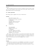
Specifications for modules Typical Use The ADSR is Typically used for generating amplitude envelopes through a VCA, or spectral envelopes by modulating the frequency of the filter modules. An ADSR can also be used to obtain an auto wah wah effect as shown in Figure 88 under Vbandpass2. Figure 21: Amplitude envelope created with ADSR Note: 6.3 See also ADAR, VADSR and VADAR modules. After Touch The After Touch module is used to send the after touch control from a MIDI keyboard.
6.5 Audio In 67 Input1 1 1 0 0 Input2 1 0 1 0 Output 1 0 0 0 Table 1: And module output as a function of its inputs. 6.5 Audio In The Audio In module is used to process external audio in Tassman. The output of this module is a monophonic signal from a track or a bus of a host sequencer where the Tassman has been inserted as an effect.
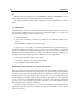
Specifications for modules Typical Use To ensure a good signal/noise ratio and avoid distortion due to excessive loudness, the Audio Out is often used in conjunction with a Volume and a Level. Figure 23: Use of an Audio Out Note: There must be an Audio Out in your patch if you want to hear you instrument. See also Stereo Audio Out. 6.7 Bandpass2 The Bandpass2 module is a second-order band-pass filter (-6dB/octave).
6.7 Bandpass2 69 Amp dB Q = 0.01 Q = 0.1 Q=1 Q = 10 Frequency Hz Center Frequency Figure 24: Frequency response of a Bandpass2. Amp dB Resulting Filter Filter 2 Filter 1 Filter 3 Frequency Hz Figure 25: Response of the parametric equalizer shown in Figure 26. Figure 26: Parametric equalizer made with a Bandpass2. Note: See also Vbandpass2.
6.8 Specifications for modules Beam The Beam module simulates sound produced by beams of different materials and sizes. This module first calculates the modal parameters corresponding to beam-shaped objects according to the value of the different parameters requested at construction time and, next, calls the Multimode module to simulate sound production by the beam. The module has one output, the sound produced by the beam, and three inputs.
6.9 Bowed Beam 6.9 Bowed Beam 71 The Bowed Beam module simulates sound produced by bowed beams of different materials and sizes. This module first calculates the modal parameters corresponding to beam shaped objects depending on the value of the different parameters requested at construction time and, next, calls the Bowed Multimode module to simulate sound production by the beam. The module has one output, the sound produced by the beam, and three inputs.
Specifications for modules the direction of the motion. The second input signal is a force signal which is considered to act perpendicularly to the motion of the beam. Third input is a pitch modulation signal. Typical Use. See Bowed Multimode module. The default value of the following parameters is set during construction • Length: the length, in meters, of the beam. • Frequency: fundamental frequency, in Hertz, of the beam when there is no pitch modulation signal or when its value is equal to 0.
6.12 Bowed Multimode 73 Typical Use. See Bowed Multimode module. The default value of the following parameters is set during construction • length: the length, in meters, of the membrane. • Width: the width, in meters, of the membrane. • Frequency: fundamental frequency, in Hertz, of the membrane when there is no pitch modulation signal or when its value is equal to 0. Note that the fundamental frequency is independent of the size of the membrane.
Specifications for modules patterns that can be used to decompose a complex motion. By adding together modes having different frequencies, amplitudes and damping, one can reproduce the behavior of different type of structures. The accuracy of the resulting signal depends on the number of modes used in the simulation. The Bowed Multimode module is not directly accessible to the user.
6.12 Bowed Multimode 75 Force The force knob is a gain knob acting on the force input of a Bowed Multimode object. Velocity The velocity knob is a gain knob acting on the velocity input of a Bowed Multimode object. Noise The noise knob is used to set the amount of irregularities in the bow structure. Damping vs Frequency In a mechanical structure, the damping, or decay time, varies for the different frequency components of the oscillating motion.
Specifications for modules 6.13 Bowed Plate The Bowed Plate module simulates sound produced by bowed rectangular plates of different materials and sizes. This module first calculates the modal parameters corresponding to plate shaped objects according to the value of the different parameters requested at construction time and, next, calls the Bowed Multimode module to simulate sound production by the plate. The module has one output, the sound produced by the membrane, and three inputs.
6.14 Bowed String 6.14 Bowed String 77 The Bowed String module simulates sound production by bowed strings of different materials and sizes. This module first calculates the modal parameters corresponding to string shaped objects according to the value of the different parameters requested at construction time and, next, calls the Bowed Multimode module to simulate sound production by the string. The module has one output, the sound produced by the string, and three inputs.
Specifications for modules The default value of the following parameters is set during construction • MIDI channel: MIDI channel used by the breath controller. 6.16 Comb The Comb filter enhances frequency components located at harmonic intervals. The frequency response of the filter is composed, as shown in Figure 29, of resonances around frequency components located at multiples of a fundamental frequency (hence its name).
6.16 Comb 79 can be modulated by using the modulation inputs of the module. The amount of variation of the resonance frequency obtained with the modulation inputs depends on the adjustment of the mod1 and mod2 gain knobs. The total modulation signal is the sum of the two inputs each multiplied by the gain corresponding to its respective mod knob. When the knobs are in the center position (green LEDs on), the gain equals 1 and the resonance frequency variation is 1 Volt/octave.
Specifications for modules 6.17 Compressor The Compressor module is used to automatically compress or expand the dynamics of a signal. This module has two inputs and one output. The first input is the signal to be compressed and the second input is a control signal which triggers the compression process when it rises above a given threshold. This control signal is usually the same as the input signal. The gain in slider is used to adjust the level of both the input and control signal.
6.19 Control Voltage Sequencer 81 Figure 31: The pitch of a Plate module adjusted with a Constant module. 6.19 Control Voltage Sequencer The Control Voltage Sequencer module enables you to record sequences of voltage. This module in itself does not produce sound but is used, usually instead of a Keyboard module, to control other modules such as VCO, VCA or filters. This module is a very complete 16-step sequencer, which means that it plays sequences or patterns of 16 notes in loop.
Specifications for modules The sequencer will loop each time a pattern ends. To make the sequencer stop at the end of a pattern the once button must be clicked. The patterns can be played following 5 play modes using the mode control. Forward (FWD) plays the pattern incrementally. Backward (BWD) plays the pattern decrementally. Pendulum (PEND) plays the pattern forwards then backwards. Random 1 (RDN1) plays the pattern randomly, the same random sequence is repeated when looping.
6.20 Control Voltage Sequencer with Songs 6.20 Control Voltage Sequencer with Songs 83 This module is the same as the Control Voltage Sequencer but with song mode added. For more information about the song mode, please refer to the Multi Sequencer module documentation. Note: see also Multi-Sequencer, Control Voltage Sequencer, Single Gate Sequencer, Single Gate Sequencer with Songs, Dual Gate Sequencer and Dual Gate Sequencer with Songs. 6.
Specifications for modules The default value of the following parameter is set at construction • MIDI channel: MIDI channel used by the sustain pedal. 6.22 Delay gain The Delay module is a feedback loop with a variable delay in the feedback. There is one input and one output. The input signal is sent into the feedback loop. The output is the sum of the input signal and the returning signal from the feedback loop. The duration of the delay can be adjusted, with the time knob (between 10 ms and 1.
6.23 Dual Gate Sequencer 6.23 Dual Gate Sequencer 85 The Dual Gate Sequencer module enables you to record two sequences of gates at the same time. This module in itself does not produce sound but is used, usually instead of a Keyboard module, to trig other modules such as Player or drum sounds. This module is a very complete 16-step sequencer, which means that it plays sequences or patterns of 16 notes in loop. Sequences can be set to have 1 to 16 steps.
Specifications for modules The tempo display will adjust the speed of the pattern. The ext/int switch will determine if it is the internal clock (int) that sets the tempo or an external source (ext) such as another sequencer or a Sync Lfo. The swing knob will introduce a swing feel to the rhythm of the pattern. The gate buttons control the gate output. The gate output will generate a square pulse of 1/8 of a quarter note for each active gate buttons.
6.25 Flanger 87 This module is the same as the Dual Gate Sequencer but with song mode added. To read more about song mode, please refer to the Multi Sequencer module documentation. 6.25 Flanger The Flanger module implements the effect known as “flanging” which colors the sound with a false pitch effect caused by the addition of a signal of varying delay to the original signal. This module has two inputs and one output.
Specifications for modules Amp Amp Short Delay Time Long Delay Time 0 dB 0 dB Frequency Frequency Figure 37: Frequency response of a Flanger module. Effect of the length of the delay line. Light effect (mix=0.1) Amp Medium effect (mix=0.25) Strong effect (mix=0.5) 0 dB f0 2xf0 3xf0 4xf0 5xf0 6xf0 Frequency Figure 38: Effect of the mix between “wet” and “dry” signal on the frequency response of a Flanger module No Feedback Amp Feedback = 0.5 Feedback = 0.
6.25 Flanger 89 Tuning The delay length is adjusted with the delay knob and is displayed, in milliseconds, in the counter next to the knob. The length of this delay can be modulated by using the second input of the module, the amount of modulation depending on the adjustment of the depth knob.
Specifications for modules The default value of the following parameters is set during construction • delay: time delay, in seconds, applied to the input signal (values between [0, 92]ms). • feedback: coefficient,[0, 1[, determining amount of “wet” signal re-injected into the delay line. If feedback = 0 there is no “wet” signal re-injected while if feedback = 0.99, maximum of “wet” signal re-injected. • depth: gain coefficient, [0,1], multiplying the modulation signal.
6.27 Gain, Gain 2, Gain 3, Gain 4 91 In the following example, a Flute module is controlled with a Keyboard module. The ADSR is used to shape the driving pressure signal. Note: 6.27 For polyphonic flute-like sounds, use the Organ module. Gain, Gain 2, Gain 3, Gain 4 The Gain, Gain 2, Gain 3 and Gain 4 knob modules have respectively one to four inputs and one to four outputs. They are used to adjust the amplitude of a signal.
Specifications for modules Sub-patches may have between 0 and 12 inputs and 0 and 12 outputs but they must always have at least one input or output. As soon as an Inlet or Outlet module is included in a patch, the Tassman Builder will consider that you want to define the current patch as a sub-patch and will save it as so in the Sub-Patches folder of the Browser. You can then use it just like any other module. Typical Use A sub-patch is created with an Inlet or Outlet module or both.
6.31 Keyboard 93 This module is to invert the control voltage generated by an ADSR so that the cutoff frequency of a VCF module first goes down when triggering a new note as shown in Figure 43. The inverter can also be used to obtain a stereo tremolo effect (amplitude modulation) as illustrated in Figure 44. Figure 44: Stereo tremolo effect. 6.31 Keyboard The Keyboard module simulates the outputs of a classic monophonic analog high-note priority keyboard. It has no input and two outputs.
Specifications for modules Note: 6.32 see also the Vkeyboard and Polykey and Polyvkey modules. Knob The Knob module is used to adjust the amplitude of a signal. It acts in the same way as the Slider module. It has one input and one output. The output signal is the input signal multiplied by a constant varying between 0 and 2 (+6dB). Typical Use The Knob module is used whenever the level of a signal must be adjusted.
6.35 LFO (Low Frequency Oscillator 6.35 LFO (Low Frequency Oscillator The LFO module has no input and one output. The output is a periodic signal with frequency varying between 0.1 and 35 Hertz depending on the setting of the frequency knob. The oscillation of the two red LEDs on the front panel give an indication of the output frequency. The wave shape is set by the wavetype switch. Waveforms include triangle, square random and sine. The amplitude of the output signal is ±1 Volt.
Specifications for modules 6.36 Lin Gain This module is used to modify the amplitude of a signal. It has one input, the signal to be adjusted, and one output, the adjusted signal. The amplitude of the signal is a controlled with the amount slider on the front panel. The output signal is the input signal multiplied by a gain having a value between the min and max range set in the dialog of the module in the Builder. 6.37 Lowpass1 The Lowpass1 module is a first order low-pass filter (-6dB/octave).
6.39 Mallet 97 amp dB res=0.02 res=0.1 res=0.5 res=1 2d -1 ct O B/ frequency Hz cutoff frequency Figure 47: Frequency response of a Lowpass2. 6.39 Mallet The Mallet module is used to simulate the force impact produced by a mallet striking a structure. It is usually used in combination with acoustic objects such as the Beam, Membrane, Plate and String modules in order to play them.
Specifications for modules is connected to a pitch signal, the stiffness exactly follows the pitch variation so as to ensure that the spectral content (or color) of the sound produced by a structure is uniform when the pitch is varied. The third input also modulates the stiffness, but in the reverse manner as for the second input so that the stiffness of the mallet decreases when the input signal increases.
6.41 Master Recorder Trig 99 The default value of the following parameters is set at construction • Length: the length, in meters, of the beam. • Frequency: fundamental frequency, in Hertz, of the beam when there is no pitch modulation signal or when its value is equal to 0. Note that the fundamental frequency is independent of the length of the beam. The software automatically calculates the physical parameters necessary to obtain the required fundamental frequency.
Specifications for modules adjust its clock source switch to ext. Finally use the pat mode of the Sequencer and press on the once button in order to make the Sequencer stop at the end of the sequence. Note that the pitch output from the Sequencer, connected in this example to a VCO module, could be used to control any other modules you would like to record. Figure 49: A Master Recorder Trig is used with a Master Sync Input and a Sequencer to cut a perfect loop. Note: 6.
6.43 Membrane 101 Figure 50: A Master Sync Input is used to synchronize a Multisequencer module. 6.43 Membrane The Membrane module simulates sound production by rectangular membranes of different materials and sizes. This module first calculates the modal parameters corresponding to membrane shaped objects according to the value of the different parameters requested at construction time and, next, calls the Multimode module to simulate sound production by this object.
Specifications for modules • Excitation point-y: y-coordinate, in meters, of impact point from the lower left corner of the membrane. • Listening point-x: x-coordinate, in meters, of listening point from the lower left corner of the membrane. • Listening point-y: y-coordinate, in meters, of listening point from the lower left corner of the membrane. Note: For more details on this module and especially the front panel controls, see the Multimode module. 6.
6.46 Multimode 103 and mechanics and is used to describe complex vibrational motion using modes (elementary oscillation patterns which can be used to decompose a complex motion). By adding together modes of different frequencies, amplitude and damping, one can reproduce the behavior of different type of structures. The accuracy of the resulting signal depends on the number of modes used in the simulation. The Multimode module is not directly accessible to the user.
Specifications for modules Damping vs Frequency In a mechanical structure, the damping, or decay time, varies for the different frequency components of the oscillating motion. The variation of the damping with frequency is another characteristic of the material of a structure and is adjusted, in a Multimode object, with the damp/frq knob on the module front panel. In the left position, the decay time of low frequencies is shorter than that of high frequencies; in the right position it is longer.
6.47 Multi-sequencer 105 bar containing four quarter notes, each step of the sequencer itself represents a sixteenth note. The module can memorize 32 different sequences between which you can switch while playing. The sequences can also be chained in any order with the Song mode. This module has three inputs and seven outputs.
Specifications for modules The numbered gate buttons control the gate output signal. The output will generate a square pulse of 1/8 of a quarter note with an amplitude of 1 Volt for each active gate buttons. To hear a step, the gate button must be clicked (green light on). The loop buttons are used to set the length of the Pattern from 1 to 16 steps. Song Mode The sequencer can play patterns individually or in a programmed order using a song.
6.48 Nand 6.48 Nand 107 The Nand module performs the inverse of the logical AND operation. The one output of this module is either 1 (true) or 0 (false) depending on the values sent to the two inputs. This module has no front panel. The following diagram shows the output value depending on the values in the two inputs. Input1 1 1 0 0 Input2 1 0 1 0 Output 0 1 1 1 Table 2: Nand module output as a function of its inputs. Input signals are considered False (0) when smaller than 0.
Specifications for modules adjusted with the mod1 knob. The greater the amplitude, the greater the stiffness. This modulation input is used, for example, when a variation of the stiffness of the mallet with the note played is desired.
6.53 On/Off, On/Off2, On/Off3, On/Off4 109 6.53 On/Off, On/Off2, On/Off3, On/Off4 The On/Off, On/Off 2, On/Off 3 and On/Off 4 switch modules have respectively one to four inputs and one to four outputs. Their behavior is very simple: when the buttons are in the Off position, the output is zero regardless of the input signals and when the buttons are pushed in the On position, the output signal is the exact copy of the input signals.
6.55 Specifications for modules Organ The Organ module simulates a simple polyphonic street pipe organ. Every note played on the organ excites a pipe of different length, thereby changing the pitch. This module has three inputs and one output. The first input is a gate signal, generally that from a Keyboard. The second input is the driving pressure signal and is generally connected to the output from an ADSR module or the gate signal from a Keyboard module.
6.57 Panpot 111 Tassman Builder will consider that you want to define the current patch as a sub-patch and will save it as so in the Sub-Patches folder of the Browser. You can then use it just like any other module. Typical Use A sub-patch is created with an Inlet or Outlet module or both. The outputs of the sub-patch are determined by connecting them to an Outlet module. See example of Figure 42 under Inlet. Note: 6.57 See also the Inlets (1-12) modules.
Specifications for modules Figure 55: Panpot modulated by LFO. The default value of the following parameters is set at construction • Angle: default source position. A value of 0 positions the source on the left, 0.5 in the middle and 1 on the right. • Range: determines the maximum possible amount of source excursion from its original position, varies between 0 and 0.5 (90 degrees). 6.
6.58 Phaser 113 mix Fourth order All Pass Filter + Output Signal feedback Input Signal Figure 56: Phaser algorithm. increased, these peaks become sharper. The functioning of the Phaser is very similar to that of the Flanger module. The filtering effect is different however, since the Phaser module only introduces rejection around two frequencies which, in addition, are not in an harmonic relationship. Light effect (mix=0.1) Amp Medium effect (mix=0.25) Strong effect (mix=0.
Specifications for modules frequency varies between 0 and twice the value set with the frequency knob. The feedback knob is used to fix the amount of “wet” signal re-injected into the delay. Finally, the mix knob determines the amount of “dry” and “wet” signal sent to the output.
6.59 Pickup 115 objects (such as a string or a beam) near the pickup. As such an object vibrates near a pickup, the latter outputs an oscillating signal determined by the varying distance between the object and the pickup. The waveform of the output signal can be varied by adjusting the pickup position relative to the object. pickup magnet pickup coil symmetry The Pickup module has one input and one output. The input can be any oscillating signal that one wants to process through the Pickup.
Specifications for modules The Pickup module is used in Figure 60 to construct an electric piano. In Figure 61, a Pickup module is used as a distortion. The effect is applied to the signal coming out from a Polyphonic Mixer. Figure 61: A Pickup used as a distortion. The default value of the following parameters is set at construction • symmetry: vertical position of the pickup relative to the oscillating object. This parameter varies between -2 and 2, 0 is exactly in front of the object.
6.62 Player 117 the plate thus shortening the decay time of the sound produced by the structure. When the signal is greater than 0, dampers are raised. Note that this damping adds to the natural damping of the plate itself. If this input is not connected to any other module, the default value is set at 0 which implies that the plate motion will be damped.
Specifications for modules be sent to any other module for processing. The input signal is a gate signal, typically the gate signal from a Keyboard, or a Sequencer which triggers the Player according to the gate-trignone selector. When the selector is at the gate position, the Player starts whenever a low-to-high transition occurs and stops whenever a high-to-low transition occurs. When the selector is at the trig position, the Player starts whenever a low-to-high transition occurs.
6.63 Plectrum 6.63 Plectrum 119 The Plectrum module is used to simulate the excitation of a string when it is plucked by a finger or a pick. The output of this module is the force signal applied by the plectrum on the string. Before a string starts to vibrate, the plectrum moves the string. A force is supplied to the string while the plectrum and the string are in contact. The shape of the force signal is dependent on the stiffness of the plectrum which can be adjusted with the stiffness knob.
Specifications for modules The default value of the following parameters is set at construction • Strength: value of the impact force (value between 0 and 2). • Stiffness: value of plectrum stiffness (value between 1 and 20000). 6.64 Polykey The Polykey module reads signal from a MIDI keyboard and is used to create polyphonic instruments. This module must always be used in combination with a Polymixer module.
6.65 Polymixer 121 Figure 63: Creating a polyphonic synth with a Polykey and Polymixer module. The default value of the following parameters is set at construction • pitch wheel range: determines the range of pitch variation that can be obtained with the pitch wheel. The convention is 1 Volt/octave (maximum value is 2 Volts). A semitone is equal to a 0.08333 value. • MIDI channel: MIDI channel used by the keyboard.
Specifications for modules 6.66 Polyvkey Similar to the Polykey module except that there is an additional output which is proportional to the velocity with which the key was pressed. The stretch knob on the interface is used to simulate stretched tuning used on instruments such as pianos. Turned to the left, low notes will be tuned higher and high notes lower (inner stretch); turned to the right, low notes will be tuned lower and high notes will be higher (outer stretch).
6.67 Portamento 123 amp time =1s time=0.25s time=0.1s input signal time Figure 64: Behavior of Portamento as a function of time constant. amp +1V +1V gate signal time amp input signal time amp output signal time Figure 65: Portamento triggered by gate signal. Typical Use The Portamento is often used to create a glissando effect between two notes. Figure 45 shows a complete example of a Portamento triggered by a gate signal (when the on/off switch is off).
Specifications for modules Figure 66: Portamento used with Keyboard. The default value of the following parameter is set at construction • glide time: sets the time constant of the integrator (values between 0.01s and 10s); the higher the time constant the slower the response of the integrator. 6.68 Recorder The Recorder module is used to record the output of an instrument to a sound file. This module has two inputs which are respectively the left and right channel signals to be recorded.
6.69 Recorder2 125 See also the Player and Recorder2 modules. 6.69 Recorder2 The Recorder2 module is used to record the output of an instrument to a sound file. This module has 3 inputs which are respectively the gate signal and the left and right channel signals to be recorded. Recording is triggered from the module front panel or from the gate signal according to the gate-trig-none selector.
6.70 Specifications for modules Reverberator The Reverberator module is used to recreate the effect of the reflexion of sound on the walls of a room or a hall. These reflexions add spaciousness to the sound and make it warmer, deeper, and more “real”. This makes sense as we always listen to instruments in a room and thus with a room effect. This module has two inputs, the left and right source signals and its two outputs are these signals as they would be heard in a given room.
6.70 Reverberator 127 a real room the reverberation time is not constant over the whole frequency range. As the walls are often more absorbent in the very low and in the high frequencies the reverberation time is shorter for these frequencies. This can be adjusted in the Reverberator module with the low and high decay knobs. Another parameter which affects the response of a room is its geometry; the more complex the geometry of a room, the more reflexion are observed per unit of time.
Specifications for modules 6.71 RMS The RMS (Root Mean Square) module is an envelope follower. Its output is the root mean square of the input signal. The inverse of the integration time (1/τ ) is set during construction and determines the response time of the circuit. This module has no front panel control. amp amp input signal amp ouput signal T=0.1s time output signal T=0.01s time time Figure 69: RMS value of a signal.
6.72 Sample & Hold 129 Figure 71: Use of RMS in Vocoder. 6.72 Sample & Hold The Sample & Hold module performs a sample & hold function. It has two inputs, the first a triggering signal and the second the signal to be sampled. The module has one output which holds the last sampled value of the second input. The second input is sampled every time a low-to-high transition is detected in the signal of the first input. The level of a signal is considered to be “high” for amplitudes above 0.
Specifications for modules 0.75V 0.25V time time time Figure 72: Behavior of Sample & Hold module. Figure 73: A Sample & Hold module is used to generate pseudo random signals. 6.73 Sbandpass2 This module is a static second-order band-pass filter (-6dB/octave). It is the same as the Bandpass2 module but without the playing interface. The center frequency and resonance are static and set at the time of construction. Typical Use See Vocoder example, Figure 71, under RMS module.
6.74 Selector2, Selector3 and Selector4 131 • resonance: resonance around the center frequency. 6.74 Selector2, Selector3 and Selector4 The Selector module comes in 3 flavors: Selector2, Selector3 and Selector4. These modules have 2, 3 or 4 inputs respectively and one output. The purpose of these modules is to connect the input corresponding to the position of the knob on the front panel to the output. Typical Use Selector modules can be used when one wants to change the cabling of a synth.
Specifications for modules 261.6 Hz, which corresponds to the C3 key on a piano (middle C). The range switch transposes the pitch one or two octaves up or down. The reading on the counter gives the frequency of the output signal, in Hertz, when there is no modulation signal. The second input is used to give the module an estimate of the pitch of the original signal in order to minimize the artifacts it introduces.
6.76 Single Gate Sequencer 133 sequence represents a bar containing four quarter notes, each step of the sequencer itself represents a sixteenth note. The module can memorize 32 different sequences between which you can switch while playing. This module has three inputs and four outputs. the first input is a sync signal which controls the tempo from an external source, the second is a start/stop input which will start the sequencer when it goes form 0 to 1 volt and stop it when it goes from 1 to 0 volt.
Specifications for modules Figure 76: Single Gate Sequencers controlling Player modules. Note: see also Multi-Sequencer, Control Voltage Sequencer, Control Voltage Sequencer with Songs, Single Gate Sequencer with Songs, Dual Gate Sequencer and Dual Gate Sequencer with Songs. 6.77 Single Gate Sequencer with Songs This module is the same as the Single Gate Sequencer but with song mode added. To read more about song mode, please refer to the Multi Sequencer module documentation.
6.78 Slider 6.78 Slider 135 The Slider module is used to adjust the amplitude of a signal. It acts in the same way as the Knob module. It has one input and one output. The output signal is the input signal multiplied by a constant varying between 0 and 2 (+6dB). Typical Use The Slider module is used whenever the level of a signal must be adjusted. Note: See also Gain, Selector, Volume.
Specifications for modules Note: See also Audio In. 6.81 Stereo Audio Out The Stereo Audio Out module is used to output stereo signals. It has two inputs, the first sent to the left audio channel of the sound card, the second to the right channel. For the saturation characteristics of this module, refer to the Audio Out module. Typical Use A stereo signal can be produced from a mono signal using a Panpot module.
6.82 Stereo Chorus 137 Input Signal Output Left Signal mix + left variable delay line left feedback + cross feedback + right feedback + right variable delay line mix Output Right Signal Figure 78: Stereo Chorus module. Tuning The length of the delay lines associated with the left and right channel, are adjusted with the delay left and delay right knob respectively. The length of the two lines are displayed, in milliseconds, in the counter next to these knobs.
Specifications for modules The default value of the following parameters is set at construction • delay: time delay, in seconds, applied to the left and right input signals (values between [0, 92]ms). • feedback: coefficient,[0, 1[, determining amount of “wet” signal re-injected into the delay lines. If feedback = 0 there is no “wet” signal re-injected while if feedback = 0.99, maximum of “wet” signal re-injected. • depth: gain coefficient, [0,1], multiplying the modulation signal.
6.84 Sync delay 139 Figure 79: A String exciting a Plate. parameters necessary to obtain the required fundamental frequency. The default value of this parameter is 261.62 Hz which corresponds to the middle C (C3) of a piano keyboard. This setting is convenient when controlling a String module with a Keyboard module. Decay: proportional to the decay time of the sound produced by the string. • Inharmonicity: detunes the partial toward higher frequencies with respect to the fundamental.
Specifications for modules very low frequencies used as control signals rather than audio ones. It has two inputs and three outputs. The first input is the sync input signal which is used to sync the module to an external source. The second input resets the waveform at the beginning of its cycle each time a signal above 0.1 Volt is received. The first two outputs are the same as the first two inputs and are used to control other Sync LFO or Sequencers.
6.86 Sync Ping Pong Delay 141 Left Ouput Left Input Lowpass Pan Left Delay Line Feedback Mix Lowpass Right Delay Line Right Ouput Right Input Figure 80: Ping Pong Delay algorithm. length of the delay line which is adjusted to fit the number of steps appearing in the display, four steps representing a quarter note. The feedback knob is used to adjust the amount of signal reinjected from the end of one line into the input of the other one.
6.87 Specifications for modules Toggle The Toggle module is a clock divider. This module has two inputs and one output. The first input is the clock signal to be divided. The second input is used to reset the circuit. The output is the input signal with a frequency divided by two. To perform this operation properly, this module should only be used with clock signals in the first input. 6.88 Tone wheel The Tone wheel module is used to build combo organs.
6.89 Tremolo 143 Timbre The timbre of the output of the tone wheel can be varied with the flute reed selector. In the left position, the module outputs a sine-like tone. As the selector is turned to the right, the signal gets distorted and evolves toward a triangle-like tone as its harmonic content increases. Typical Use Tone wheel modules are usually used in parallel. In the example of Figure 82, three modules are connected to a polyphonic Keyboard module.
6.90 Specifications for modules Tube The Tube module simulates sound propagation in a cylindrical tube of a given length and radius. The effect of a tube is to color an input signal by enhancing frequencies located around its resonance frequencies. When the tube is very long, it produces an echo effect. The source is assumed to be at an extremity of the tube. The output of this module is the signal that would be measured by a microphone placed at the other extremity of the tube.
6.90 Tube 145 Amplitude of the tube resonances The amplitude of the resonances can be adjusted with the radius of the tube when it is open at the listening point. At the extremity of a tube sound energy is radiated toward the exterior, the termination in fact acting like a low-pass filter. Increasing the radius of the tube, both increases the amount of energy radiated (thereby decreasing the amplitude of the tube resonances) and lowers the cutoff frequency of the filtering effect of the termination.
Specifications for modules 6.91 Tube4 The Tube4 module simulates sound propagation in a resonator made from 4 tubes of variable lengths and radii connected in series as shown in Figure 85. The input signal, or source, is assumed to be localized at the extremity of the first tube while the output, or listening point, is placed at the extremity of the fourth tube.
6.92 Tube Reverb 147 • termination: specifies whether the final tube is open or closed at its extremity. A value of 0 indicates that the tube is closed and a value of 1 that it is open. Note: 6.92 For more details on the filtering effect of tubes see the Tube module. Tube Reverb The reverb effect obtained with this module is obtained with an assemblage of three tubes. The tubes are assumed to be connected at one of their extremities and the sound source to be located at this connection point.
Specifications for modules Typical Use In the example of Figure 87, two Tube Reverb modules are used to make a stereo reverb effect. The Reverb modules are adjusted with short tubes in order to simulate early reflections in a room. The Tube4 module is used to introduced a delay and simulate late reflections. Figure 87: A stereo reverb. The default value of the following parameters is set at construction • length: length, in meters, of the 3 tubes (between 0.01 and 1000m).
6.94 VADSR 149 The modulation entries can be connected to the velocity output of a Vkeyboard or a Sequencer module. Note: 6.94 See also the ADAR, ADSR and VADSR modules. VADSR The VADSR acts exactly like the ADSR module except that the VADSR has four additional inputs for controlling each phase of the envelope. It also had four more knobs for adjusting the gain of these four inputs.
Specifications for modules Center Frequency Variation The amount of variation of the center frequency obtained with the modulation inputs depends on the adjustment of the mod1 and mod2 gain knobs. The total modulation signal is the sum of the two inputs each multiplied by the gain corresponding to its respective mod knob. When they are in the center position (green LEDs on), the gain equals 1 and the pitch variation is 1 Volt/octave.
6.97 VCO (Voltage Controlled Oscillator) 151 Typical Use A VCA is mainly used to apply an amplitude envelope to a signal. An ADSR can be used to supply the appropriate gain signal. Figure 89: ADSR as Gain Signal to VCA. Figure 90: VCA in Ring. A VCA can also be used to obtain a ring modulation effect. In this case the gain signal is a sine wave around 50 Hz. Note: Since a multiplication operation is involved, the order of the inputs is not important.
Specifications for modules Tuning the Output Pitch The coarse and fine knobs and the range switch are used to tune the output frequency (or pitch) to the desired level. The variations in output pitch caused by changes in the modulation signals are relative to this level. When the two knobs are in their center position (green LED on for the coarse knob), the range switch is set to 8 and there is no modulation signal, the playing frequency has a value of 261.
6.98 VCS 153 Typical Use The VCO is used for generating the starting signal of an analog synthesizer. Figure 92 shows a standard patch using this module. Figure 92: Typical VCO Use. 6.98 VCS The VCS module is very similar to the VCO module except that it only generates sine waves. This module has 2 modulation inputs and 1 output. The first input controls the pitch of the output signal. The signal of this input is multiplied by a value determined by the adjustment of the mod1 gain knob.
Specifications for modules Pitch Variation The amount of variation of the playing frequency obtained with the modulation inputs depends on the adjustment of the mod1 and FM gain knobs. The total modulation signal is the sum of the two inputs each multiplied by the gain corresponding to their respective knob. When the mod1 knob is in the center position (green LEDs on), the gain equals 1 and the pitch variation is 1 Volt/octave.
6.100 Vkeyboard 155 relative to this level. The resonance knob is used to emphasize the frequencies near the cutoff frequency as shown in the following figure: Cutoff Frequency Variation The amount of variation of the cutoff frequency obtained with the modulation inputs depends on the adjustment of the mod1 and mod2 gain knobs. The total modulation signal is the sum of the two inputs each multiplied by the gain corresponding to its respective mod knob.
Specifications for modules The default values of the following parameters is set at construction • pitch wheel range: determines the range of pitch variations that can be obtained with the pitch wheel. The convention is 1 Volt/octave (maximum value is 2 Volts). A semitone is equal to a 0.08333 value. • MIDI channel: MIDI channel used by the keyboard. 6.101 Vlowpass2 The Vlowpass2 module is a voltage-controlled second-order low-pass filter (-12dB/octave). This module has three inputs and one output.
6.102 Vlowpass4 157 When the modulation signal is the pitch output from a Keyboard module, this position can be used to make the cutoff frequency follow an equal temperament scale. The modulation signal of the second input can be inverted by pressing the inv button. This can be useful when generating bass sounds, for example, where one wants to close the filter with an upward going envelop such as during the attack of a note.
Specifications for modules 6.103 Volume The Volume module is used to adjust the amplitude of a signal. It has one input and one output. The output signal is the input signal multiplied by a constant varying between 0 and 2 (+6dB). Typical Use The Volume module is used whenever the level of a signal must be adjusted. A Volume is usually placed just before an Audio Out module (see Figure 22.
Quick references to commands and shortcuts 7 159 Quick references to commands and shortcuts File Menu Command PC Mac OS Description New Ctrl+N Apple+N New patch Apple+Shift+N New Folder in the Browser Apple+O Open the selected patch Apple+W Close the window and exit the application New Folder Open Instrument Ctrl+O Close Close Current Patch Ctrl+W Apple+Shift+W Close the current patch Save Instrument Ctrl+S Apple+S Save the current patch Save Instrument As Save the current patc
Quick references to commands and shortcuts Edit Menu Command PC Mac OS Description Undo Ctrl+Z Apple+Z Undo last command Redo Ctrl+Y Apple+Shift+Z Redo last command Cut Ctrl+X Apple+X Cut selected item Copy Ctrl+C Apple+C Copy selected item Paste Ctrl+V Apple+V Paste Delete Del Select All Ctrl+A Apple+A Select all items Duplicate Ctrl+D Apple+D Duplicate selected item Info Ctrl-I Apple+I Edit information about a selected item (browser) Module Settings Alt-Enter
Quick references to commands and shortcuts 161 Edit / Preferences Menu Command PC Mac OS Description General Display the Edit General Preferences window Audio Settings Display the Audio Settings window Midi Settings Display the MIDI Settings window Latency Settings Display the Latency Settings window Arrange Menu Command PC Align Left Edges Alt-Left Align the left edges of the selected modules (builder) Center Horizontally Shift F9 Align horizontally the selected modules (builder) Alig
Quick references to commands and shortcuts View Menu Command PC Mac OS Description Show Player/Builder Ctrl-T Apple-T Toggle between the builder and player views Apple-B Show/Hide the browser panel Show/Hide Browser Show/Hide Help Show/Hide the help panel (builder) Locate Ctrl-L Apple+ Select and make visible in the browser the current instrument or the module currently selected in the builder Previous Patch Ctrl-Shift-Tab Apple+= Walk forward in the list of opened instruments Next
License Agreement 8 163 License Agreement IMPORTANT! CAREFULLY READ ALL THE TERMS AND CONDITIONS OF THIS AGREEMENT BEFORE OPENING THIS PACKAGE. OPENING THIS PACKAGE INDICATES YOUR ACCEPTANCE OF THESE TERMS AND CONDITIONS. IF YOU DO NOT AGREE WITH THE TERMS AND CONDITIONS OF THIS AGREEMENT, PROMPTLY RETURN THE UNOPENED PACKAGE AND ALL COMPONENTS THERETO TO THE PARTY FROM WHOM IT WAS ACQUIRED, FOR A FULL REFUND OF ANY CONSIDERATION PAID.
License Agreement 4. LIMITED WARRANTY. Except for the foregoing, THE SOFTWARE IS provided “AS IS” without warranty or condition of any kind. AAS disclaims all warranties or conditions, written or oral, statutory, express or implied, including but not limited to the implied warranties of merchantable quality or fitness for a particular purpose, title and non-infringement of rights of any other person.
License Agreement 165 Contracts for the International Sale of Goods and conflict of laws provisions, if applicable, and the parties hereby irrevocably attorn to the jurisdiction of the courts of that province. Les parties sont d’accord à ce que cette convention soit rédigée en langue anglaise. The parties have agreed that this agreement be drafted in the English language. 8. SEVERABILITY.
Index acoustic objects, 39 adar, 64 adsr, 28, 65, 90, 93, 151 after touch, 66 analog synth, 18 and, 66 audio configuration, 12 audio device, 54 audio in, 67 audio out, 67, 94 bandpass2, 68, 102 beam, 70, 97, 98, 103 bowed beam, 71, 74 bowed marimba, 71, 74 bowed membrane, 72, 74 bowed multimode, 71–73, 76, 77 bowed Plate, 76 bowed plate, 74 bowed String, 77 bowed string, 74 breath controller, 77, 90 browser, 60 customizing, 62 filters, 63 buffer size, 56 builder, 8, 45 chorus, 89 comb, 78 commands, 159 comp
INDEX help, 16 highpass1, 91 hold, 129 import, 61 inlet, 91, 110 installation, 9 instruments, 56, 60 creating, 14, 45, 46 playing, 53 saving, 18, 25, 49 inverter, 92 keyboard, 25, 26, 90, 93 monophonic, 93 polyphonic, 120, 122 knob, 94 knobs, 53 tweaking, 53 latency, 56 less, 94 level, 24, 68, 94, 158 lfo, 20, 79, 89, 95, 112, 114, 129 library, 45 lin gain, 96 logic gates and, 66 less, 94 nand, 107 nor, 108 not, 108 or, 109 xor, 158 lowpass1, 96 lowpass2, 96 mallet, 39, 97, 104, 107 marimba, 83, 98, 103 ma
plate, 40, 80, 97, 103, 116, 139 Player, 52 launching, 18, 52 layout, 52 player, 8, 86, 117, 132 launching, 18 plectrum, 119 plug-in, 15 Audio Units, 16 DXi, 15 RTAS, 15 VST, 16 polykey, 120, 121 polykeyboard, 26 polymixer, 120, 121 polyphony, 25, 31, 50, 120, 121 polyvkey, 122 portamento, 122 preset, 56, 60 default, 57 loading, 33, 57 saving, 33, 57 sub-patches, 57 INDEX programming, 37 single gate, 132 single gate with songs, 134 using, 37 shifter, 131 shortcuts, 159 single gate sequencer, 132 sing
INDEX vkeyboard, 26, 155 vlowpass2, 21, 156 vlowpass4, 82, 157 vocoder, 129 volume, 24, 68, 80, 158 wah, 114 wah wah, 150 wire, 45 editing, 18, 47 xor, 158 169