MPR-1510BR 2.7e1 Page 1 11/10/2006 SENTINEL-SENSE MPR-1510B-RM 2.
MPR-1510BR 2.7e1 Page 2 11/10/2006 COPYRIGHT ACKNOWLEDGEMENTS The contents of this document are the property of Applied Wireless Identifications Group, Inc. (AWID) and are copyrighted. All rights reserved. Any reproduction, in whole or in part, is strictly prohibited. For additional copies of this document please contact: AWID 18300 Sutter Blvd Morgan Hill, CA 95037 http://www.AWID.
MPR-1510BR 2.7e1 Page 3 11/10/2006 SAFETY INFORMATION FOR RF EXPOSURE IMPORTANT NOTE: FCC Radiation Exposure Statement: This equipment complies with FCC radiation exposure limits set forth for an uncontrolled environment. End users must follow the specific operating instructions for satisfying RF exposure compliance. This device is intended only for OEM integrators under the following conditions: 1. The antenna must be installed such that 20cm is maintained between the antenna and users; and 2.
MPR-1510BR 2.7e1 Page 4 11/10/2006 U.S.A. U.S.FEDERAL COMMUNICATIONS COMMISSION RADIO FREQUENCY INTERFERENCE STATEMENT INFORMATION TO THE USER NOTE : This equipment has been tested and found to comply with the limits for a Class B digital device pursuant to Part 15 of the FCC Rules.
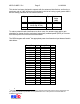
MPR-1510BR 2.7e1 Page 5 11/10/2006 This device has been designed to operate with the antennas listed below, and having a maximum gain of 6 dBi. Antennas not included in this list or having a gain greater than 6 dBi are strictly prohibited for use with this device. Mfg AWID AWID Model Type MPR2010ANT Patch 915CPS-A (with 8ft cable Patch AWID PN: RTC8) Snyder 1x4 Dipole Dipole Maximum Gain (dBi) 5.59 4.9 2.
MPR-1510BR 2.7e1 Page 6 11/10/2006 Table of Contents 1 INTRODUCTION.................................................................................................................. 7 1.1 2 SPECIFICATIONS................................................................................................................ 8 2.1 2.2 2.3 3 Channel Frequency Table ................................................................................................ 8 Connector Pin Assignment .......................
MPR-1510BR 2.7e1 1 Page 7 11/10/2006 INTRODUCTION AWID's Sentinel-Sense MPR-1510B-RM Rev. 2.7e1 (MPR-1510BR 2.7e or simply 2.7e) is a long-range (12 to 15 feet) Radio Frequency IDentification (RFID) Reader Module with RS-232 I/O interface that works with most leading passive UHF passive tags. This reader comes with a unique combination of long read range, small size, and low power consumption.
MPR-1510BR 2.7e1 2 Page 8 11/10/2006 SPECIFICATIONS Input voltage Input current Protocol language +7.0 VDC to +15 VDC 1.0 A (7.0 V) to 0.40 A (15 V) typical ISO Type B (Intellitag, UCODE EPC V1.19 Rev 2), EPC Class 1 Gen 1 & 2, EM Depends on type & size of labels used +30 dBm max 902.75~927.25 MHz 902.75~927.25 MHz (Amplitude Modulated) 50 Channels 500 kHz Pseudo random -30° C to +65° C (-22° F to 149° F) RS-232 Version: DB-9 connector 3”x5”x0.
MPR-1510BR 2.7e1 2.3 Page 9 11/10/2006 MEASURING READ DISTANCE Make sure you know the tag types. For certain readers and tags, user must also be mindful of the tag’s orientation and the reader’s antenna orientation, what mounting surface the tags are designed for and how the tags are supposed to be mounted. Any departure from its intended purpose will drastically affect the reader’s ability to energize the tag and its read range.
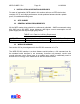
MPR-1510BR 2.7e1 3 Page 10 11/10/2006 INSTALLATION & OPERATION GUIDELINES For ease of explanation, MPR reader in this section refers to an RFID device that consists of 2.7e and a high performance circular polarized antenna inside a splash proof, UV stabilized housing case. 3.1 SITE SURVEY 3.2 GENERAL WIRING REQUIREMENTS All the MPR reader wiring should be continuously shielded.
MPR-1510BR 2.7e1 4 Page 11 11/10/2006 INSTALLATION PROCEDURE This section provides installation and operation information for MPR readers. 4.1 PARTS LIST Verify that all items listed below are present before starting the installation. o Sentinel-Sense MPR-1510BR 2.7e o Documentation and Demo Program CD 4.2 Qty=1 Qty=1 PREPARATION FOR INSTALLATION Familiarize yourself with the connectors and pin out assignment of each I/O connectors. 4.2.
MPR-1510BR 2.7e1 5 5.1 Page 12 11/10/2006 SOFTWARE PROGRAMMING AND SYSTEM OPERATION NOTES SYSTEM OPERATION 5.1.1 Running a Custom Software Application or the AWID Demo Program If AWID Demo Program is not used, it is expected user will launch a Custom Software Application developed using the MPR Serial Communication Protocol to send commands as specified to the MPR reader. 5.1.
MPR-1510BR 2.7e1 Page 13 11/10/2006 If you are using the AWID RFID demonstration software application which is .NET based with easy-to-follow GUI operations, simply select the COM port for which the MPR reader is configured then click “Connect” should get you started.