
User's Manual

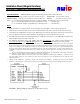
Table Of Contents
- Reader Description
- Parts List (a) Installation Sheet 1
- Installation Procedure
- Operation Modes NDK-2025 Reader supports the following operation modes of the host system:
- 1. Power down before any wiring changes. Connect the black wire (ground) first, and the red wire (power) last.
- 2. When the brown and yellow wires are not used, the LED and beeper remain active, under the reader’s internal control.
- 3. The LED, Beeper and Hold lines are logic levels. Never apply power to them. They may be pulled to the low logic level (0 to 1.2V DC) to enable their function, and float at the high logic level (3.6 to 5.0V DC) when not used.
- 4. The NDK-2025 card reader has both Wiegand-protocol and RS-232 serial interfaces. The NDK-2025 keypad has only 26-bit Wiegand output on the same 2 data lines.
- 5. For additional information, please visit AWID’s Web site www.awid.com. For technical support questions visit www.awid.com/support or call 1-800-369-5533 (in the U.S.) or +1-408-825-1100 from 8:00 a.m. to 5:00 p.m. PST.
- 6. FCC Compliance: This equipment has been tested and found to be in compliance with the limits for FCC part 15, Class A digital device. These limits are designed to provide reasonable protection against harmful interference when the equipment is operated in a commercial environment. This equipment generates, uses and can radiate radio frequency energy and, if not installed and used in accordance with instruction manual, may cause harmful interference with radio communications. Operation of this equipment in a residential area is likely to cause harmful interference in which case the user will be required to correct the interference at his own expense.
- The users are prohibited from making any change or modification to this product. Any modification to this product shall void the user’s authority to operate under FCC Part 15 Subpart A Section 15.21 regulations.
- This device complies with Part 15 of the FCC Rules. Operation is subject to the following two conditions: (1) This device may not cause harmful interference, and (2) this device must accept any interference received, including interference that may cause undesired operation.
- 7. Industry Canada Compliance: Operation is subject to the following two conditions: (1) This device may not cause harmful interference, and (2) this device must accept any interference, including interference that may cause undesired operation of the device.

NDK-2025 Reader with Integrated Keyp
ad V1.1 Page 1 of 4
Installation Sheet (Wiegand Interface)
NDK-2025 Reader with Integrated Keypad
Reader Description
The NDK-2025 Reader is a radio-frequency proximity reader with integrated keypad for Access Control
Systems. The Reader consists of a 12-key PIN pad, transmit/receive antenna, and reader electronics, in a durable
metal housing. The reader and keypad electronics are potted with urethane resin to protect against the
environment. The NDK-2025 Reader may be mounted like a cover plate on a single-gang electrical utility box,
or on any surface.
Parts List (a) Installation Sheet...............................................1
(b) Sentinel-Prox NDK-2025 Reader …….. ...... 1 (c) #6-32 x 1” machine screw.................................2
Installation Procedure
1. Install a single-gang electrical utility box, or drill two no. 27 (0.144 inch) clearance holes for the reader’s
screws and one hole for the cable, at the desired location. Observe ADA height requirements.
2. Clip off the white 10-pin in-line connector from the end of the reader’s cable. Keep the wires as long as
possible.
3. Remove reader’s back plate, and install it on an electrical utility box or other surface. The supplied screws
can be used to fasten the back plate to a utility box (item c in the Parts List).
4. Connect the reader’s cable to the access control panel as shown in Figure 1. Connect the yellow wire only if
used for Beeper control by the panel. In steps 8 and 9, let the yellow wire float. Connect the blue wire only
if used for Hold control by the panel. Do not connect the orange and violet wires to anything. Tape or cap
all unused wires singly.
5. For red and black wires, use a linear regulated DC power supply, between 5V and 12V. (Minimum 1A)
6. Fasten the reader to its back plate, with supplied screw.
7. Power up the reader. The beeper will sound and the LED will be a steady amber color.
8. While the LED is amber, enter the 10-digit password (914 369 880 0). There is a short beep with each
keystroke. (For security, record this password and store it in a safe place.)
9. Immediately enter the 5-character code #SSS# for the site code (or facility code) that you will program into
the host system to recognize keypad PIN entry. SSS represents the 3-digit site code. There is a short beep
with each keystroke.
• Program the host system for 26-bit Wiegand format from keypad entry. The site code must be between
000 and 255.
• If you do not enter the keypad’s site code, the NDK-2025 Reader-Keypad enters a default site code of
000.
• The site code for the keypad may be the same as or different from the site code of the credentials (cards,
keytags or wafers), depending on requirements of the host system or the application.
10. If programming is successful, the beeper sounds 1 long beep. Then the LED is steady-red to indicate
Standby mode.
11. If the beeper doesn’t sound and the LED doesn’t change to red, remove power from the reader for a few
seconds; then repeat steps 7 to 10, above. Enter the 10-digit password and the 5-character code without
interruption, pressing each key for at least one-half second. Do not pause between the password and the 5-
character code. Also, be sure that the yellow wire is disconnected from the panel and floating during the
programming.
12. The LED color in Standby mode may be changed from red to green, or from green to red, using a Color
Changer card, available from AWID. Remove power from the reader for a few seconds; then restore power.
When the LED is amber, present the Color Changer card to toggle the LED’s Standby color.