
Installation Instructions

Instructions LR-911, Part 2 14 September 2005 Page 3 of 8
B. PRE-INSTALLATION TESTING
1. Introduction
Careful preparation is important for successful installation of AWID’s long-range readers and tags.
Each moment spent at the installer’s shop preparing for the actual work at the installation site will pay
dividends. For additional information and technical support, contact AWID at support@awid.com
or phone toll-free 800-369-5533 (outside the United States, 845-369-8800).
2. Items for Bench Testing
AWID’s long-range reader and tags are tested easily using only the items listed below. It is not necessary
to interface the reader to a controller panel or reader-input module while conducting this test.
• LR-911 reader (does not contain an LED)
• GMWS windshield tag attached to glass *
• MT metal-mounting tag *
• SP-6820-LR test unit, cable with 3 clips *
• PS12-1A power module, cable with 2 clips *
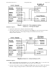
• Wiring diagram, Figure 1 (on page 7)
* A component of the LRIN Installation Kit
3. Supporting the Reader
The reader’s “surveillance zone” (that is, the effective RF field in which the long-range tags
can be detected) is maximized when there is no material in front of the reader or immediately to the sides
of the reader. See the LR-911 Surveillance Zone Diagram (attached).
• Hang the reader on a clear vertical surface in an open space, about 4 feet above the bench top,
4 feet from a side wall, and 4 feet below the ceiling.
• Æ Connect the wires as shown in the wiring diagram, Figure 1 (on page 7). Read the notes carefully.
• Be sure that unused wires are touching nothing. Do not cut off unused wires yet.
• The first connection made should be the reader’s black (electrical ground) wire.
• The last step should be to plug in the DC power module.
4. Wiring for Quick Test
Æ See the wiring diagram, Figure 1, and notes (on page 7).
Proper operation of the reader and tags is indicated by a signal from the SP-6820-LR test unit each time
that the tag is read. The LED changes briefly from standby Red to Green, and a short beep (4 kHz tone)
is heard. If the tag remains in the reader’s surveillance zone, reads repeat at about 3 per second
(factory default rate).
5. Holding the Tag
• Hold the GMWS test tag by pressing the opposite edges of the glass rectangle between the thumb and
middle fingertip, with the hand behind the glass (away from the reader). Or …
• Hold the MT tag by pressing either end of the tag at the screw hole between thumb and finger tips.
• Hold either tag so that the face of the tag is approximately parallel with the reader’s face. (The reader
is circular-polarized, so the tags may be held at any angle – up-and-down, or side-to-side, or diagonal.)
• Move the tag slowly though the surveillance zone in front of the reader, observing the edges of the zone
and the point of maximum read range.