
User's Manual

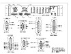


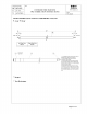


Table Of Contents

ANTENNA INSTALLATION
The antenna system and ACU, which are exclusively installed in mass transit rail cars,
must be professionally installed in accordance with these instructions.
The ACU is to be installed in the utility cabinet of the “B” rail car of a “married pair” rail car
pair. See the Antenna Connection drawing 550320-ANT.
The ACU connects to the antenna system as shown in 550230-ANT.
The Leaky Feeder Antenna’s are made in accordance with drawing RC-WI-002 by terminating
one end in a 50-ohm resistor and connecting the other end to an N male connector.
The components required for the Antenna System assembly are as follows:
ITEM QTY MFG PN NOTES
Power Splitter, 2-Way, “F” 2 Steren 201-202
Adapter, BNC M to F Fe 6 Steren 200-108 For use on power
splitters
Antenna, Leaky Feeder,
80”
2 Times
Microwave
T-RAD-600FR See drawing RC-WI-
002
Connector, N Female 2 Times
Microwave
EZ-600-NF Attaches to one end
of Antenna
Coax Cable Times
Microwave
LMR-195 See drawing 550320-
ANT
Connector, BNC Male 8 Amphenol 31-4320 Crimped to LMR-195
at ACU and 2-Way
Splitter
Connector, N Male 2 Amphenol 82-5375-RFX Crimped to LMR-195
at antenna.
Resistor, 50 Ohm, leaded 2 Vishay/Dale RN60D49R9F
B14
The “A” output port of the ACU connects to the “A” rail car antenna system, which is furthest
from the ACU. This port has 4-dB more output power than the “B” ACU port to compensate for
the additional line losses to the “A” rail car.
The B port of the ACU is connected to the “B” rail car antenna system, which is the rail car in
which the ACU is installed.
The antennas are installed at ceiling level. They are spaced 40 feet apart, 17.5 feet from each
end of the rail car.
Specific assembly and routing installation information for cables, antenna and other components
of the audio/video system can be found in the manual, Interior Wire Harness Pre-Fabrication
Instructions, RC-WI-002.
Page 6 of 19