INSTALLATION & OPERATION MANUAL IP CAMERA LC-7314 (PAL) Before trying to connect or operate this product, please read this manual completely
Table Of Contents SAFETY PRECAUTIONS .............................................................................3 1. PRODUCT FEATURES.............................................................................4 1.1 PRODUCT INSTRUCTIONS .....................................................................4 1.2 PRODUCT FEATURES ...........................................................................4 2. DESCRIPTION OF THE FRONT/REAR VIEW .........................................8 2.
.6 CONNECTION TESTING .......................................................................23 5. Operating Instructions for Image Software and Network..................25 5.1 MICROSOFT INTERNET EXPLORER ......................................................26 5.1.1 Connecting the IP Camera ...............................................................................................................26 5.1.2 Change Image Setting .............................................................................
SAFETY PRECAUTIONS All the following safety and operational instructions to prevent harm or injury to the operator(s) or other persons should be read carefully before the unit is activated. WARNING To prevent fire or shock hazard, avoid exposing this unit to rain or moisture. Do not block ventilation openings. Do not place anything on top of the unit that might spill or fall into it.
1. PRODUCT FEATURES 1.1 Product Instructions The newly designed H.264 / MJPEG stream IP camera provides simultaneous video codec streams of H.264 and MJPEG in 520 TV lines. This IP camera not only supports the 25 fps frame rate, motion detection and built-in microphone, but also the day and night, and pre- and post-alarm functions.
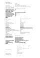
Video Codec: Video compression: H.264 Motion JPEG 720 x 576 (PAL) 352 x 288 (PAL) Simultaneous H.264(720 x 480 and 352 x240) Resolutions: Video streaming: Video Codec – MJPEG: Motion JPEG frame rate: Up to 25 fps at 720 x 576 (PAL) Motion JPEG rate control: Yes Motion JPEG quality level: 5 Video Codec – H.264: H.264 Frame rate: Up to 25 fps at 720 x 576 (PAL) H.264 frame rate control: Yes Customized H.264 bit rate: Yes H.264 bit rate control: Yes H.
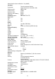
Network active alarm notification: Yes (ANNP) Hardware: Texas Instruments DaVinci Processors: High performance 32-bit RISC CPU DDRII memory: DDRII 1Gbit Flash memory: 256Mb Real-time clock: Built-in Real-time clock battery: Built-in Watchdog: Built-in Firmware upgrade: SD Card/FTP/HTTP Approvals: FCC: Yes CE: Yes RoHS: Yes Power: DC 12V: Yes Max (TBD Watt) AC 24V: Yes PoE: Power over Ethernet (IEEE 802.
File system: Recording format: Network play-back: SD card brand verified: Device Indicator: Ethernet Link: Ethernet Active: System Operation: System Warning: Accessories: Accessories: PTZ Support: Protocol: I/O Ports: USB: DHCP/Static IP switch: DC IRIS/AES switch: Factory Reset: RS-485: Alarm input: Alarm output: Alarm reset: Audio I/O: DC-OUT: FAT32/16/12 JPG/AVI Yes A-Data/ PQI/ Toshiba/ Transcend/ APacer/ Photo Fast Yes Yes Yes Yes USB cable CD-Rom C-Mount ring Power Adapter Quick installation guide P
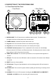
2. DESCRIPTION OF THE FRONT/REAR VIEW 2.1 Front Panel and Rear Panel -- Front Panel -- -- Rear Panel -- 1 3 4 5 AC 24V ETHERNET (PoE) DC 12V VIDEO 6 1 12 RESET USB SD / SDHC ! 2 6 7 8 9 10 11 1. MICROPHONE: The IP Camera has an additional audio function. The device has a microphone built into its front panel which records sound. 2. POWER indicator: Indicates the power status of the unit. 3. Plug Inlet: A DC 12V inlet that connects to an external power supply. 4.
2.2 ALARM I/O 1.ALM-OUT A 2.ALM-OUT B 3.ALM-IN + 4.ALM-IN 5.ALM-RST + 6.ALM-RST - 7.RS-485:D+ 8.RS-485:D9.DC-OUT(5V) 10.GND 11.AUDIO-IN 12.AUDIO-OUT 1 & 2. ALARM OUT (OUTPUT): This is an alarm output trigger. Connect this to external 5V, 20mA devices such as buzzers or lights. ( 0V(Active) ) 3 & 4. ALARM IN (INPUT): This is an alarm input that can be programmed in the menu 5V, 20mA system to active low. ( 0V(Active) ) 5 & 6.
2.3 Flank Panel IRIS 1.ALM-OUT A 2.ALM-OUT B 3.ALM-IN + 4.ALM-IN 5.ALM-RST + 6.ALM-RST - 7.RS-485:D+ 8.RS-485:D9.DC-OUT(5V) 10.GND 11.AUDIO-IN 12.AUDIO-OUT 1. AES 1 3 2 4 2. DC IRIS 3. DHCP 4. STATIC IP 1 1. 2 IRIS: Auto iris connector. This camera works with a DC drive auto iris lens. Please refer to the pin assignment marked on the camera when connecting the auto iris lens 2. DIP Switch: 1. AES: Auto electric shutter. 2. DC IRIS: Use an auto iris (DC drive) 3.
2.4 The USB function By connecting the IP Camera with a PC via the USB connector, the IP Camera can provide two different functions. 1. Insert an SD card: As a card reader. Insert an SD card into the IP Camera, then connect to the PC. You might transfer files between the SD card and the PC. Once you've connected your IP Camera to your computer, the Windows system will detect the connection and ask you what you want to do with your SD card.
3. INSTALLATION Please follow the instructions and the diagram below to set up the system. NOTE: The IP Camera is linked by its Video Out connection via a BNC connector to a monitor's Video In connection. If this connection is there, you can see some information on the monitor screen, such as the IP Camera factory default Static IP address(192.168.1.168). But the IP Camera Static IP address can only appear if there is a connection between the IP Camera and another device.
3.3 CONNECTING WITH A MULTIPLEXER LAN CAMERA 1 LAN CAMERA 2 TO LAN CAMERA VIDEO OUT BNC CONNECTOR LAN CAMERA 16 3.4 UPDATING SYSTEM SOFTWARE If the system software of the IP Camera needs to be upgraded, please take the following steps to safely process it. Important: Before carrying out the following procedures, please ensure the SD card is working and the file of the system firmware is intact 1.
9. If the message "UPDATE NG RESET PLEASE" appears rather than "UPDATE OK RESET PLEASE", please write down the error messages shown on the screen and inform your technical support, while ignoring the following steps. 10. Power off the IP Camera when this update process is finished, then remove the SD card from the IP Camera. 11. Reconnect the Ethernet cable to the RJ-45 port if necessary. 12. Power ON the IP Camera and it will work normally if the entire update procedure goes correctly. 13.
3.5 IP Camera SD card Troubleshooting 1. Check if the SD card position is correct or not. Please refer to the manual for the related information. 2. After powering the IP Camera on, correctly insert the SD card, and a little icon of "SD" will show up in the upper-right corner of the monitor screen. If not, it means the device detection has failed. Please contact your technical support and ignore the following steps. 3. If no cross sign appears beside the "SD" icon, please go on to the next step.
4. Network Configuration 4.1 Cable Connections Please follow the instructions below to connect your IP Camera to a computer or a network and to choose a proper RJ-45 cable configuration for connections. Physical specifications of the RJ-45 cable for Ethernet Wire Type Cat. 5 Connector Type RJ-45 Max. Cable Length 100 m Hub Wiring Configuration Straight Through or Cross Over PC Wiring Configuration Straight Through or Cross Over 4.1.
4.1.2 Connect to a LAN Hub (INTRANET) The RJ-45 PIN configuration for connecting with a LAN Hub is shown below.
4.2 Configure Your IP Camera Network Settings Upon connecting with the network hardware, you need to activate the network function and configure the proper network settings of the IP Camera. 4.2.1 Enable DHCP Function This function can only work if the LAN, which the unit is connected to, has a DHCP server. If the DHCP server is working, please move the dip switch points up to 3 on the flank panel; now the IP Camera will obtain an IP address automatically from the DHCP server.
NOTE: When connecting to a network, each connected IP Camera must be assigned a unique IP, which must be in the same class type as your network address. IP addresses are written as four sets of numbers separated by periods; for example, 192.168.1.1 Therefore, if the connected network is identified as Class C, for example, the first three sets of numbers of the IP Camera’s IP address must be the same as the network address.
4.3 TCP/IP Communication Software Follow the procedure below to install the TCP/IP communication program in your computer. Click the Start menu from your computer, and point to the Settings/Control Panel. Double click the Network icon to enter the windows.
Click the Configuration tag, and check if the TCP/IP is included among the network components list. If the TCP/IP is included, please process section 4.5. If it is not included, please follow section 4.4 to install the TCP/IP. 4.4 TCP/IP Installation During the installation, you will be requested to insert the Windows CD-ROM. After installation, the PC may be restarted.
4.5 TCP/IP configuration setting Click Start → Settings → Control Panel → Network. Select TCP/IP, and then click Properties. Before processing the IP Camera installation in a WAN, please make sure the Internet connection works properly. If not, please contact your ISP provider. If you are using a DHCP server, please select Obtain an IP address automatically. Any assigned IP address for the connected IP Cameras must be in the same class type as the server.
4.6 Connection Testing With the previous settings, follow the instructions below to ensure whether you have established the connection successfully. Click Start → Programs → MS-DOS Prompt Type in ping 192.168.1.168, then enter. (See the sample screen below). ** This IP is the IP Camera’s IP address that is assigned for the connected IP Camera in step2.
If you receive a response as in the sample screen below, the connection hasn’t been successfully established. Please re-check all the hardware and software installations by repeating steps 1 to 5. If you still can’t establish the connection after rechecking, please contact your dealer. Type Camera IP address If you receive a response as in the sample screen below, you have successfully made the connection.
5. Operating Instructions for Image Software and Network Two choices of software are available for linking with the IP Camera: (1) the Microsoft Internet Explorer; and (2) the IP Camera VIEWER, a network browser in a PC which provides the functions of monitoring remote zones or watching recorded data through the TCP/IP protocol. The details are listed as follows. RJ-45 PIN configuration for Ethernet PIN NO. 1. 2. 3. 4. 5. 6. 7. 8.
5.1 Microsoft Internet Explorer 5.1.1 Connecting the IP Camera 1. Start up the Microsoft Internet Explorer, and then follow the steps below to connect the IP Camera. 2. Click the URL block at the top of the window. 3. Enter the URL address of the IP Camera into the URL block and press the “Enter” button to enter the home page. 4. Scroll to the bottom of the page, with its six icons, "Image", "Network", "System", "Application", "SD card" and “Pan/Tilt”.
Browsing images from the IP Camera The images from the IP Camera will be displayed on the home page while going online with the IP Camera. Some buttons of the home page are provided for further setting. In MJPEG mode or in H.264 mode, there are different display formats of its home page. Scroll to choose the image mode from “H.264” or ”MJPEG”. Homepage of H.264 mode Homepage of MJPEG mode Click the Image button to enter the image-setting page. Click the Network button to enter the network-setting page.
5.1.2 Change Image Setting Please follow the steps below to change the image setting through the network if necessary. 1. Click the Image button on the home page to enter the image-setting page. 2. Adjust the image setting including “Device Title” and “Viewer Type” if necessary. 3. Click the Submit button to submit the new image setting. 4. Click the Multi Profile button to enter the MultiProfile image-setting page. Select an ID (1-6) from the drop-down list then set its resolution and quality.
5. Click the H.264 Image button to enter the H.264 image-setting page. Adjust the image setting including “Resolution”, “Quality” and “Frame Rate” if necessary. 6. Click the Submit button to submit the new image setting. 7. Click the Fine Tune button to enter the Image Fine Tune page to set the details of the device including: ”White Balance”, “Flickerless”, “Mirror”, “High Speed Shutter”, “BLC Mode”, “Backlight”, “Brightness”, “Contrast”, “Saturation”, “Sharpness” and “videoalc”.
8. Click the Privacy Mask button to enter the Privacy Mask page. 9. Click the Day & Night button to enter the Day & Night page. Click the drop-down list to choose the Day & Night mode of “Auto”, “Day mode”, “Night mode” and “Schedule”. Set the values of Focus Adjust and Sensitivity. Click the Submit button to submit the new Day & Night setting.
10. Click the Home button to return to the home page while the new image setting acts on the images to effect the desired changes instantly. (If the setting has not been changed by the above steps, any (re)entry onto the home page will find images in their earlier or original setting.) Description of function keys: Device Title: Type in the camera title in the given space.
5.1.3 Change the Network Setting Please follow the steps below to change the network setting through the network if necessary. Set the network options and IP address. 1. Click the Network button in the home page to enter the Network page. 2. The accessible networks here are the “FTP”, “SMTP”, “SNTP”, “DDNS”, “PPPoE”, ”UPnP”, ”IP Filter” and the ”Traffic”. 3. Fill in the “IP Address”, “Netmask”, “Default Gateway”, “Primary Nameserver”, and “HTTP Port” if necessary. 4.
Description of function keys: IP Address: Enter the 4-byte IP Address in the appropriate blank space (the value in each box may be anywhere between 0 and 255). Every IP camera has to own an IP address to be identified on the network. Netmask: Fill in the 4-byte Subnet Mask in the required blank spaces (usually any numbers between 0 and 255). It is used to identify the subnet where the IP camera is sited.
Change the Network Setting — FTP. Please follow the steps below to change the FTP setting via the network if necessary to upload recording data live. 1. Click the FTP button at top left to enter the “FTP Server Setting” page. 2. Type in the “FTP Server” address, the “User Name”, and the “Password” of the FTP Server; and set the “File Upload Path” of the image files when necessary. 3. Click the Submit button to submit the new FTP setting of the recording. 4. Click the Home button to return to the home page.
Change the Network Setting — SMTP. Please follow the steps below to change the SMTP setting through the network if necessary. 1. Click the SMTP button at upper left above to enter the “SMTP Server Setting” page. 2. Click “My Server Requires Authentication” to checkmark the attached box and activate the function. 3. Fill in the Sender name, DOMAIN NAME of the SMTP server, and set the recipient’s e-mail address if necessary. 4. Click the Submit button to submit the new SMTP setting. 5.
Change the Network Setting — SNTP. Please follow the steps below to change the SNTP setting through the network if necessary. 1. Click the SNTP button at upper left above to enter the “SNTP Server Setting” page. 2. Enter the IP Address of the SNTP server, and choose one of the time zones as and when necessary. 3. Click “Automatically Adjust for Daylight Saving Time Changes” to checkmark the attached box and activate the function. 4. Click the Submit button to submit the new SNTP setting. 5.
Change the Network Setting — DDNS. The “Network” page has, on its upper left, the “DDNS” icon. Please follow the steps below to change the DDNS setting through the network if necessary. 1. Click the DDNS button at upper left above to enter the “DDNS Setting” page. 2. Click “Enable DDNS Function” to checkmark the attached box and activate the function. 3. Click ”DDNS Type” to open the list of two DDNS modes to choose from: “DynDNS” and “hn”.
Description of function keys: Enable DDNS Function: Checkmark to activate the function. DDNS Type: Click to open the list of two DDNS modes to choose from: “DynDNS” and “hn”. Click the “Apply” button and connect this website automatically and enter it. Type in your dynamic IP Address and Email Address. If they are accepted by the website, you will get an Email containing your DDNS Account and DDNS Password in your Email box. DDNS Host Name: Type in your host name in the attached space.
Change the Network Setting — PPPoE. The “Network” page has, on its upper left, the “PPPoE” icon. Please follow the steps below to change the PPPoE setting through the network if necessary. 1. Click the PPPoE button at upper left above to enter the “PPPoE Setting” page. 2. Please read the “PPPoE Troubleshooting” document first, then press “Close’ button. 3. Click the “PPPoE mode” to activate the function. 4. Type in the PPPoE “Account” and the PPPoE “Password”. 5.
Change the Network Setting —UPnP. The “Network” page has, on its upper left, the “UPnP” icon. Please follow the steps below to change the UPnP setting through the network if necessary. 1. Click the UPnP button at upper left above to enter the “Universal Plug and Play” page. 2. Click “Enable UPnP” to checkmark the attached box and activate the function. 3. Type in the UPnP “Max Expired Age”, the “SSDP Port” and the “UPnP Port”. 4.
Change the Network Setting — IP Filter The “Network” page has, on its upper left, the “IP Filter” icon. Please follow the steps below to change the IP Filter setting through the network if necessary. 1. Click the IP Filter button at upper left above to enter the “Network Setting” page. 2. Click “Enable IP Filter” to checkmark the attached box and activate the function. 3. Select the Default policy. 4. Set the Allow/Deny IP Filter policy and enter its IP address. 5.
Change the Network Setting —Network Traffic. The “Network” page has, on its upper left, the “Traffic” icon. Please follow the steps below to change the UPnP setting through the network if necessary. 1. Click the Traffic button at upper left above to enter the “Network Traffic” page. 2. Type in the “Maximum Upload Bandwidth” and the “Maximum Download Bandwidth”. 3. Click the Submit button to submit the new setting. 4. Click the Home button to return to the home page.
5.1.4 Change the System Setting Please follow the steps below to change the date and time of the system setting through the network if necessary. Set the Date and Time of the system 1. Click the System button in the home page to enter the “Date And Time” page (default). 2. Choose one of the three modes shown on the page to set the Date and Time of the system. The three modes are “Set Manually”, “Synchronize With Computer Time”, and “Synchronize With SNTP Server”. 3.
Change the System Setting — Timestamp. Please follow the steps below to change/add the timestamp through the network if necessary. 1. Click the Timestamp button on the left side of the “System - Date and Time” page to enter the “Timestamp” page. 2. Click “Enable Timestamp” to checkmark the attached box and activate the function 3. Add or modify any timestamp’s data if necessary. 4. Enter the "Timestamp Color" you have chosen. 5. Enter the "Timestamp Location" you have chosen. 6.
Change the System Setting — Users. Please follow the steps below to change/add the users’ authority through the network if necessary. 1. Click the Users button on the left side of the “Date and Time” page to enter the “Users” page. 2. Add, modify or delete any user’s data if necessary. 3. Click the Submit button to submit the new user’s settings. 4. Click the Home button to return to the home page.
Change the System Setting — Digital I/O. Please follow the steps below to change the Digital I/O through the network if necessary. 1. Click the Digital I/O button on the left side of the “Date and Time” page to enter the “Digital I/O Setting” page. 2. Mark the “Digital Input” “ON” or “OFF” and the “Digital Output” “ON” or “OFF”. Click your choices to enable. 3. Click the Submit button to submit the new user’s settings. 4. Click the Home button to return to the home page.
Change the System Setting — Audio Mechanism. Please follow the steps below to change the Audio Mechanism through the network if necessary. 1. Click the Audio Mechanism button on the left side of the “Date and Time” page to enter the “Audio Mechanism Setting” page. 2. Mark the “Audio Mechanism” “ON” or “OFF”. 3. Choose one of the audio sources. The two sources are “Audio In” and “Mic” (microphone). 4. Click the Submit button to submit the new user’s settings. 5.
Change the System Setting — RS485 Setting. Click the RS485 Setting button on the left side of the “Date and Time” page to enter the “RS485 Setting” page. Description of function keys: Baud rate: Eight different speeds can be used: 2400 baud per second, 4800 baud, 9600 baud, 19200 baud, 28800 baud, 38400 baud, 57600 baud and 115200 baud. Type: Choose one of the types. Device ID: You have the option of using an ID code (any number between 1 and 255). Raw Format: Set to transmit the ASCII codes.
Change the System Setting — Update Firmware. Please follow the steps below to change the Audio Mechanism through the network if necessary. 1. Click the Update Firmware button on the left side of the “Date and Time” page to enter the “Update Firmware” page. 2. Click the “Browse…” button to select the UPDATE.BIN file which was copied into your computer. 3. Click the “Update” button. 4. DO NOT power off the IP Camera while this update process is running.
View the Event Logs. Please follow the steps below to view events through the network if necessary. 1. Click the Events button on the upper left above to enter the “Event Log” page. 2. Choose one of the three buttons shown on the page to view an event when necessary. The three buttons are titled “First Page”, “Previous 20”, and “Next 20”. Description of function keys: First Page: Displays the first page. Previous 20: Displays the previous 20 pages. Next 20: Displays the next 20 pages.
5.1.5 Change the Application Setting Please follow the steps below to change the application setting through the network if necessary. Change the Application Setting — FTP Application Setting. Please follow the steps below to change the FTP setting via the network if necessary to upload recording data live. 1. Click the Application button on the home page to enter the “FTP Application Setting” page (default). 2.
Change the Application Setting — SD Card Application Setting. Please follow the steps below to change the SD CARD setting via the network if necessary to upload recording data live. 1. Click the SD Card button on the top left to enter the “SD Card Application Setting” page. 2. You have an option as to which SD - card storage format to use, the MJPEG or the AVI. Click your selected format and click "Submit" to set it. 3. If it's MJPEG you want, fill in the "Max MJPEG Numbers" entry. 4.
Change the Application Setting —SMTP Application Setting. Please follow the steps below to change the SMTP setting via the network if necessary. 1. Click the SMTP button on the left side to enter the “SMTP Application Setting” page. 2. Enter the attached file number as and when necessary. The maximum number which can be used is 8. 3. Click the Submit button to submit the new SMTP setting of the recording. 4. Click the Home button to return to the home page.
Change the Application Setting —Language Setting. Please follow the steps below to change the Language setting via the network if necessary. 1. Click the Language button on the left side to enter the “Language Setting” page. 2. You have an option as to which language to use. The default is “English” 3. Click your selected language and click "Submit" to set it.
Change the Application Setting —Record Application Enable Setting. Please follow the steps below to change the setting via the network if necessary. 1. Click the Enable Record button on the left side of the record to enter the “Record Application Enable Setting” page. 2. Click “Enable Record – UPLOAD Via FTP” to checkmark the attached box and activate the function. 3. Click “Enable Record – Save Into SD card” to checkmark the attached box and activate the function. 4.
Change the Application Setting —Record - Schedule. 1. Click the Application button on the home page to enter the “Schedule” page. 2. Check/uncheck any/all of the first seven boxes set vertically in the upper half of the “Schedule” page to enable/disable the programmed recording function, and vary the setting of the targeted item while it is enabled. 3. Click the Submit button to submit the new schedule setting. 4.
Change the Application Setting — Alarm Application Enable Setting. Please follow the steps below to change the setting via the network if necessary. 1. Click the Enable Alarm button on the left side of the record to enter the “Alarm Application Enable Setting” page. 2. Click “Enable Alarm – Trigger an Alarm When Ethernet Is Lost” to checkmark the attached box and activate the function. 3. Click “Enable Alarm – Upload Via FTP” to checkmark the attached box and activate the function. 4.
Change the Application Setting —Motion Detection. Please follow the steps below to enable changes in the motion detection function of the alarm through the network if necessary. Set the motion detection: 1. Click the Motion Detection button on the left side of the Alarm to enter the “Motion Detection” page. 2. Click and drag the left mouse button across a targeted zone to draw a red rectangle on the image (coordinates provided below).
5.1.6 Change the SD card Setting Please follow the steps below to change the SD card setting through the network if necessary. Change the SD card Setting — FILELIST of MEMORY CARD. Please follow the steps below to change the setting via the network if necessary. 1. Click the “SD card” button at the bottom of the home page to enter the page containing the “FILELIST of MEMORY CARD”. The page comes in two modes, the JPEG and the AVI (please refer to the “SD card Application Setting Page”). 2.
5.1.7 Change the Pan/Tilt setting Click the Pan/Tilt button on the home page to open the Speed Dome Controller. 1. Click “Configure” to enter to the RS485 setting page (please refer to Change the System Setting — RS485 Setting). Select a Speed Dome device ID from the drop-down list on the Speed Dome Controller. The Controller will display the corresponding ID. 2. Each of the ten buttons under ‘Set’ is connected with a specific position and angle of either panning or tilting of the camera.
5.1.8 PPPoE & DDNS Using the PPPoE 1. Install the XDSL software (obtained from your ISP dealer) in your PC. 2. Search your IP Camera's IP address: you can use your Network Viewer's Scan IP program, or just connect the IP Camera and the Video monitor. The monitor screen will show the IP address on its right side. 3. Change the switch on the IP Camera's side panel to position # 4. 4. Installing an IP address in your PC or notebook.
Test: Go to the Internet. 1. Set your PC to enter the Internet. 2. Desktop → IE browser → Type in the IP Camera’s IP address (the same address as in the PPPoE settings and step 3 above) → You can see the IP Camera images. DDNS settings 1. Check your IP Camera’s IP address ( Scan IP software or monitor ) → open your IE browser → Use the address to connect to the IP Camera or view the images → Choose the network → Type in “User name : admin” and “Password : 9999” → Click “OK” . 2.
5.2 The IP Camera CMS (Central Management System) This section provides instructions for installing and using the Central Management System ( CMS ) which is included with the IP Camera. The programs can be operated by a selected PC equipped with the following requirements. System Requirements Intel Pentium 1.5 GHz processor or above (2.8 GHz or higher recommended). 128-MB RAM at least (256-MB or higher recommended). Windows 2000, XP or above. 4 MB VGA card capable of 24-bit true color display.
5.2.2 Install the CMS in your PC Install the CMS from the supported CD-R. 1. Exit all applications currently running in the selected PC. 2. Insert the supported CD in the CD-ROM drive. The program will execute the installation automatically. Follow the on-screen instructions to proceed with the rest of the installation procedure as they appear. NOTE: The program will update the .NET Framework to version 2.0 automatically. Please click “Next” to start and finish the setup process. 3.
5.2.3 Login the IP Camera software Once the CMS is executed, a Login prompter will appear. You must enter the default user name: admin, and the password: 9999 in the respective spaces (and confirm the password again the first time you log in). Click the “OK” button and enter the console page of the CMS: both the user name and password must be entered correctly. Click the “Cancel” button and exit the login of the CMS.
2. Add a channel from the Add Device page. 3. (1) Click the Auto Search button at the bottom of the "Add Device " page to discover the connection of the IP Camera-type device in the LAN. Instantly the "Search Device" page will appear. Click the device of your choice and click "Add" at the bottom of the page to access the "Add Device " page again. (2) This page provides the IP Address and the HTTP Port.
5.2.4 Operation 5.2.4.1 Device Management Once the connection has been established, click the button to enter the Device Management window ( see the sample screen below.) On the left side of the window is the connected device that has been arranged when you established the connection. 1 Add device: Add a new device. For more details please refer to section 5.2.3. Modify device: Modify the added device. Please select a device, then click this button to edit the device.
NOTE: The Device Setting page: For the further settings of each channel, please select the device title on the left side and click the setting button to enter the setting pages of the device. Click the “Setting” button to bring up the device-setting pages. You can interchange between four buttons: the “Image”, “Network”, “System” and “Application”. The method of operation is the same as the Microsoft Internet Explorer setting pages (please refer to section 5.1 for more details).
5.2.4.2 Live View Press the button to enter the Live View page. Add Live View Group: Press to add a new group of the live view. To change the group name, please left click twice on the title of the group, and then enter the new title. Group Sequence: This button enables you to see the sequential display of the group. Please select the group, and then click this button to start the display. Delete Live View Group: 1.) Select the Live View Group you want to delete from the list. 2.) Press “Yes”.
The audio function is available. Press to activate the function and the icon will turn purple “ ”. Press again to deactivate the function. Recording function: The recording function is not available. The recording function is available. Press to activate the function and the icon will turn red “ ”. Press again to deactivate the function.
5.2.4.3 PC Playback button to enter the PC Playback page. Press the 1 Click to choose the recording list by channel. Click to choose the recording list by time search. Enter the MONTH /DAY /YEAR /HOUR /MINUTE you wish to search and click the button to proceed. NOTE: The recorded video list box will show the recorded video which are stored in the HDD of the connected devices by channel or by time. : Click to use the playback-controlling panel. : Click to display the volume control panel.
: Click to set the export function. The function fits the starting and ending points of an image display, when the user wants to transfer a file. Start/ End time: Set the start and end time that you want to export (backup) the recorded files to the AVI files. Note: You also can click to select the recorded file on the recording list above. : Click to add the whole selected video to the arranged exporting list.
5.2.4.4 DVR Remote Playback (for DVR devices only) Press the button to enter the DVR Remote Playback setting page.
5.2.4.5 Config Press the button to enter the Config setting page. NOTE: After finishing the settings of each page, please click Save to save the parameters. (1) User Click the icon to enter the User setting page. User List: Add User: 1.) Click to open the Add User window. 2.) Enter the information of the Username, Password, Confirm Password and Description. 3.) Select the User Group if necessary, 4.) Now press “Add”. Modify User: 1.) Click to open the Add User window. 2.
User Information: Provides the selected user’s information of Username, Description and Group. (2) User Group Click the to enter the User Group setting page. User Group List: Add Group User: 1.) Click to open the Add Group User window. 2.) Enter the information of the Group Name and Description, then select the Authority. 3.) Set the member list from the available user list . 4.) Now press “Add”. Modify User Group: 1.) Click to open the Modify User Group window. 2.
(1) Folder for Snapshot Images: Click to select (2) Folder for Export AVI Clips: Click to select the path to save the AVI files. Image Settings: Select the aspect ratio: ( NOTE: The STRETCH status : Images are resized to full screen status. The aspect ratio status: When you resize images, they will retain their natural proportions. ) AUTO: The JPEG compression mode comes with the STRETCH status. The MPEG 4 and (1) the H264 compression modes have the aspect ratio status.
Undo: Undo the latest changes Restore Defaults: Recover the default setting. (5) Record Settings Click the 1 icon to enter the Record setting page. Click to add a new record saving path. Click to delete a selected recording path. 2 Max. Usage: Set the maximum recording quota from the drop-down list. Overwrite: Checkmark to activate the function. 3 Save: Apply the changes. Undo: Undo the latest changes. (6) Schedule Click the 1 icon to enter the Schedule setting page.
Sets the starting time of recording from the drop-down list. Sets the ending time of recording from the drop-down list. Clicks the icon to enable the just added schedule. Clicks the icon to disable the selected schedule. 2 The working area: (1) Click the working area directly to add a new schedule as you wish. (2) The functioning schedule bar is colored orange and the non-functioning schedule bar(s) is colored pink.
5.2.4.5 Tray Press the Right click the button to minimize the CMS monitor into the systray* of the Windows taskbar. button once to select the functions on the list: . *: The Microsoft Windows systray is a portion of the Windows 95, Windows 98, Windows ME, Windows NT, Windows 2000, and Windows XP Operating Systems that help display running programs. The systray is located on the taskbar and is commonly in the bottom right hand corner of the screen next to the time display.
6. ADVANCED OPERATION Question 1: How to view the live images of the IP Camera via the Microsoft Internet Explorer on the Desktop PCs or the laptop computers in a situation where there are no monitors or television? ◇The way to get the IP address of the IP Camera without a monitor: There are three ways to get the IP address: Scan IP, UPnP and IP function. Scan IP: Please refer to APPENDIX 1. UPnP: Please refer to APPENDIX 2. IP function: Please refer to APPENDIX 3.
4. Click the Submit button to submit the setting. NOTE: Please remember to insert the SD card into the built-in SD slot of the unit first. ◇Set the recording time (the AVI duration) of the SD card 1. Click the Application button in the home page into the “SD-Card APPLICATION SETTING” page. 2. Choose the AVI Duration from the drop-down list. If you want to record the file into the SD card for 30 seconds, please choose 30 seconds. 3. Click the Submit button to submit the setting.
2. Click the PPPoE button on the left side of the page to enter the “PPPoE SETTING” page. 3. Choose “ON” from the “PPPoE mode” list to activate it. 4. Enter the Account and the Password which are provided from your ISP. 5. Click the Submit button to submit the setting. NOTE: Please refer to section 5.1.8 for more details. ◇Use the Sub Hostname to view the IP Camera 1. Click the URL block at the top of the PC screen. 2.
◇Set the upload rate 1. Click the Application button. 2. Click the FTP button on the left side of the page to enter the “FTP APPLICATION SETTING” page. 3. Set the last item “Upload Rate” at the bottom of the page to the rate you want. If you want to record at the rate of 1F/8S, please choose “1F/8S” in the drop-down list. Question 5: How to add or modify the users and their authorities of using the IP Camera? ◇Entering the setting page 1. Click the System button in the home page. 2.
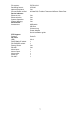
7. SPECIFICATIONS LC-7314 Video system Image system Audio Network system Connectors Application Miscellaneous H.264 CCD Box IP-Camera (PAL) Video sensor Horizontal resolution Lens Auto Iris AES Min. illumination Day & Night 1/3” Sony Super HAD CCD (with HQ1 DSP) 520 TV Lines C / CS mount DC drive 1/50 ~ 1/100000 sec 0.5 Lux @ F1.2 Yes (Mechanical IR-Cut filter) Simultaneous H.264 & MJEPG video streaming. Video compression Simultaneous multi-profile video stream.
8. Functions of client PC System requirement Windows 2000, XP or above Browser IE 6.x Live Monitor Max. 16 Split , Real Time REC/ Capture/ Audio/ Live Event/ Full Screen Playback Viewer Playback, Time / live event Search / Export (JPEG / AVI) Settings Device/ System/ Camera management/ web page Multi-camera link Max.
APPENDIX 1. –SCANIP Follow the instructions below to use the SCANIP software to search the IP camera devices from a local location. 1. Click the button to discover the connection of the all-type device in the LAN. The Device Type will display the connection of the all-type device. 2. Select the desired device from the Device Type. 3. Click the desired device to show the window while the IP camera information acts to display the desired changes instantly. 4. Do you want to manually set the IP? i.
iii. Select and double click any of the addresses in the “Free IP Address” box on the right to enter it into an IP Address on the left. iv. To change any IP address, type in the new address in the “Free IP Address” box on the right as well as the device’s login “Account” and “Password” in their respective blanks at bottom left, then click “Submit”, and the new address will automatically be sent to the device. v. Click “Exit” at bottom right to shut the device. 5.
APPENDIX 2. –IP Camera UPnP How To ® The most troublesome issue when you setup an IP Camera is that you have no idea what the IP ® address of this device is. Now IP Camera supports the UPnP (Universal Plug and Play) protocol which makes it easier for you to examine it; however, it is a pity that Microsoft Windows XP ® doesn’t start this service by default. Therefore, the following procedures will help you to turn it on ® and discover your IP Camera step by step as shown in Figure1 below.
Figure 2 Step 2: When Control Panel appears, double-click the Network Connections icon. The Network Connections dialog box appears. See Figure 3. Figure 3 Step 3: Click the Protocols tab in the Network Connections dialog box. See Figure 4. Figure 4 Step 4: When the Local Area Connection Properties dialog box shows up, choose Internet Protocol (TCP/IP) and click Properties. See Figure 5.
Figure 5 Step 5: In the Internet Protocol(TCP/IP) Properties dialog box, choose Use the following IP Address to indicate that you do not wish to use DHCP, and assign IP Address 192.168.1.200 with Subnet mask 255.255.255.0. Click OK when you finish it. See Figure 6. Figure 6 Step 6: Choose Close to finish the modification. See Figure 7.
2. Install UPnP Packets ® As described before, Microsoft Windows XP doesn’t start the UPnP service by default; however, we have to install some packets before we initialize it. The following steps will help you to install them. Step1: From the Start menu, point to Set Program Access and Default, and then click it. See Figure 8 Figure 8 Step 2: When the Add or Remove Programs dialog box appears, click the Add/Remove Windows Components button. See Figure 9.
Figure 10 Step 4: Check UPnP User Interface, and choose OK. See Figure 11. Figure 11 Step 5: When the original Network Component Wizard dialog box returns, click Next. See Figure12.
Step 6: After about one minute the UPnP installation will be done, and choose Finish to close it. See Figure13. Figure 13 3. Turn on Services After installation, we should turn on the relative services to start the UPnP protocol. The following procedures will teach you how to do it. Step 1: From the Start menu, point to Settings, and then click Control Panel. See Figure14. Figure 14 Step 2: When Control Panel appears, double-click the Administrative Tools icon.
Figure15 Step 3: Click the Services icon in the Administrative Tools dialog box. See Figure16. Figure16 Step 4: When the Services dialog box shows up, double click the SSDP Discovery Service icon. See Figure17.
Figure17 Step 5: Choose Automatic in the Startup type, and click OK to start it. See Figure18. Figure18 Step 6: When the Services dialog box appears again, double click the Universal Plug and Play Device Host icon. See Figure19.
Figure19 Step 7: Choose Automatic in the Startup type, press the Start button, and click OK to start it. See Figure20. Figure20 Step 8: Restart your system.
® 4. Scan IP Cameras through My Network Place After your installation and starting services, the UPnP protocol will take effect. You can scan all IP ® Cameras in My Network Place like Figure21 and Figure22 below. Figure21 Figure22 Just double click the UPnP IP Camera icon, and the video live stream will pop up automatically ® without assigning any IP address in Microsoft Internet Explorer .
APPENDIX 3. –The ARP function Setting the IP Address The Ethernet interface on the IP Camera has a default IP address (192.168.1.168) that most likely needs to be changed to make it work on your local network. You need to acquire a unique IP address (ask your network administrator). For the initial setting of the IP address the IP Camera needs to be connected to the same network segment as your client, and the IP address can then be configured by using a combination of ARP and ping command.
ARP and ping from UNIX or GNU/Linux: 1. Start a shell 2. Type the following as superuser (root): arp -s [or arp -s < MAC address>] ping Example: arp -s 192.168.1.100 00-0C-0C-00-00-01 ping 192.168.1.100 The device responds to the ping in the examples above if the new address was configured. Note, this method will set the IP address permanently. Note: The default account and password after the reset are admin and 9999.
APPENDIX 4. –Register as a DDNS member The DDNS(dynamic domain name system) is a function which is provided by an American company. Please refer to www.dyndns.com. This chapter provides the user with the basic instructions on how to register a free DDNS service. Registering for a DDNS Enter the URL www.dyndns.com. In the upper right-hand corner of the main page, where there is an item, ”Create Account”, as shown in Figure 1.
Figure 2 Figure 3 Click “My Services” to enter the service page. Please click the “Add Host Service” item which is below the ”My Hosts“ item, as shown in Figure 4. Click “Add Host Service”, and its service items will appear. The Add Dynamic DNS Host item helps to add a new DDNS. Each member may have only one free account, and one free account can have only five DDNS. Click Add Dynamic DNS Host to enter the DDNS setting page as shown in Figure 5.
Figure 4 Figure 5 All we have to set in this page is the “Hostname” item. The user can choose a Sub Hostname as s/he likes from the right-hand side of the Hostname’s drop-down list. NOTE: You don’t have to set the “IP Address” in the same format as the camera’s IP Address. It will renew the IP Address automatically. After finishing the setting, please press the “Create Host” button as shown in Figure 5.
Figure 6 103
APPENDIX 5. –FAQ 1. How to disable the DHCP function and use a static IP instead? A:Turn up the “DIP SWITCH” from “3” to “4” and change the relative network settings, the IP Address, NetMask and Gateway on the image web page. 2. Can the SD card be removed during recording? A:No, it cannot be removed until the recording comes to a single point. The POWER LED flashing light signals the SD card is operating. The green light indicates the unit is activating. The red light warns the SD card cannot be removed.