INSTALLATION & OPERATING MANUAL Digital Video Recorder DVR-3016 & DVR-3016D Before trying to connect or operate this product, please read this manual complete
SAFETY PRECAUTIONS All the following safety and operation instructions for the prevention of harm or damage to the operator or other persons should be read before the unit is operated. WARNING To reduce the risk of fire or electric shock, do not expose this appliance to rain or moisture. Do not block ventilation openings. Do not place anything on top of the unit that might spill or fall into it.
Table Of Contents 1. PRODUCT FEATURES .................................................................................................. 4 1.1 Product Introduction ..................................................................................................................4 1.2 Product Features .............................................................................................................................4 2. DESCRIPTION OF THE FRONT/REAR VIEW..............................................
.2 DISPLAY OPTION...................................................................................................................35 5.3 SEQUENCE SETTING ............................................................................................................38 5.4 PICTURE ADJUST ..................................................................................................................39 5.5 OPERATION LOG...........................................................................................
1. PRODUCT FEATURES 1.1 Product Introduction This 16CH DVR is a triplex digital recorder with a 16ch multiplexer, capable of Triplex simultaneous recording, playback and live multi-screen viewing; it uses two hard disks and a CD-RW drive instead of VCR tapes to store video (FOR CD-ROM MODEL ONLY). It enables you to enjoy the extreme flexibility of digital image archiving instead of clumsy tape management.
each camera). * Selectable display position and color of title/time/date OSD text in both MAIN and CALL monitors. * Covert camera recording. * Schedule setting: total 8 schedules. Individual record and alarm condition setting can be assigned by designated schedule. * Disk-full warning and operation status LEDs. * Remote control via RS-232 and RS-485 ports. * Alarm trigger source selection: alarm sensor/motion detection/video loss alarm can be programmed to trigger three different alarm out replays.
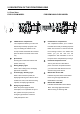
2. DESCRIPTION OF THE FRONT/REAR VIEW 2.1 Front View FOR CD-ROM MODEL 1 2 FOR REMOVABLE HDD MODEL 1 CD-RW device compartment: The compartment allows you to burn the The compartment allows you to install a data mostly for backup purposes. This hard disk drive mostly for backup purposes. tray is for loading the CD disc. It will Make sure the drive is well secured with accept 120 mm and 80 mm discs.
5 Jog Dial: This dial can act in both a forward and a backward direction, as well as step by step. Turn this left to play a recorded video in the reverse direction. Turn this right to play a recorded video in the forward direction. Moreover, the dial can be rotated so you can move the focus to any item or function. 6 Shuttle Ring: The shuttle can be moved forward and backward for playback in either direction.
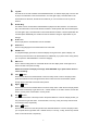
15 call button: If you connect to the call monitor, the "Call" button enables you to select channels on this monitor. Press the "Call" button and any particular channel button on the front panel simultaneously to display that channel. 16 menu button: Press this to enter the setup menu. 17 seq. button: Press to enter the sequential jumping mode, each multi-screen, and one sequential; the picture would sequentially switch to different channels according to the sequencer setting in the setup menu.
2.2 Rear View 29 30 75Ω/Hi-Z Individual termination: These 16 switches are used to set the impedance of each loop through output connectors (31) between 75Ω and Hi-Z. Toggle the corresponding impedance termination to the Hi-Z position, if another device is connected to the video loop through connector. Set the impedance to the 75Ω position if no other device is connected to the corresponding loop through the connector. The default setting is 75 Ω.
2.3 ALARM In/Out The pin assignment of the female DB-25 alarm I/O connector is listed as follows.
3. INSTALLATION Please follow the instructions and the diagram below to set up the system. 3.1 Basic Connection CONNECTING WITH 1 to 16 CAMERAS ATTACHING AN EXTERNAL DEVICE TO DVR Connect an alarm out, alarm input, and a peripheral device as shown in the diagram below.
3.2 Hard-Disk Drive Installation The 16CH DVR is equipped with two compartments of hard-disk drives and a CD-RW drive (FOR CD-ROM MODEL ONLY). The unit usually comes with one hard-disk drive installed in the compartment HD1, which is default-configured as a master. If you need a second hard-disk drive to be installed in the compartment HD2, please contact your distributors or installers for specific instructions on how to install it. Please don’t try this before consulting your installers.
3.3 HDD Information and channel selection 3.3.1 HDD information You can display the HDD information as shown on Figure 3.3 A below at any time by pressing the Display button . In the playback mode, the recorded video information is displayed. In the live or recording mode, the Manual Recording information is displayed. The unit displays status on a monitor as shown next. Figure 3.3 A. Description of Figure 3.
3.4 Updating System Software If the system software of the 16CH DVR needs to be upgraded, please take the following steps to safely update it. Important: Before carrying out the following procedures, please ensure the SD card is working and the system software file is intact. 1. Create a directory named DVRVIDEO in the SD Card; if you already have a directory, move to Step2. 2. Copy the file of UPDATE.BIN to the DVRVIDEO-directory. 3. If 16CH DVR is running, please power it off first. 4.
4. BASIC OPERATIONS This section shows you how to operate and manage the DVR. 4.1 Recording Operations This section details the way to record video into hard-disk drives. Before commencing with the recording function, please configure the recording setting properly according to your needs. 4.1.
NOTE: You can proceed to start the scheduled recording from the current time if it is in the scheduled interlude as soon as the setting is complete, and come out from the menu to start recording. NOTE: If you activate the recording function before the scheduled recording, the unit will operate recording as shown in the diagram below and keep those Images in different files.
MAIN MENU ADVANCED SETTING 1 QUICK SETTING: 2 DISPLAY OPTION: 3 SEQUENCE SETTING: 4 PICTURE ADJUST: 5 OPERATION LOG: 6 ADVANCED SETTING: 7 DEFAULT SETTING: 8 PASSWORD SETTING: 9 EXIT MENU: 1 ALARM SETTING: 2 RECORD SETTING: 3 MOTION SETTING: 4 CAMERA COVERT: 5 OPERATION LOCK: 6 COMMUNICATION: 7 DISK SETUP: 8 SCHEDULE: RETURN ENTER ENTER ENTER ENTER ENTER ENTER ENTER ENTER ENTER enter: select ▲/▼/jog/ch1~9: item menu: exit enter: select ▲/▼/jog/ch1~8: item ADVANCED SETTING SCHEDULE SETTING 1 ALARM S
4.1.3 Alarm Recording Take the following steps to activate the programmed alarm recording. For ALARM settings, please refer to section 5.6.1 for more details. (1) Press the menu button to enter the MAIN MENU. (2) Select the ADVANCED SETTING and press the Enter button to enter the ADVANCED SETTING page. (3) Select the ALARM SETTING and press the Enter button to enter the ALARM SETTING page. (4) Set the desired time period. The options range from "TRANSPARENT" to "NONSTOP", from one second to 60 minutes.
4.1.4 Externally triggered Recording By connecting the RECORD IN of ALARM I/O on the rear panel of the DVR, you can activate/deactivate the recording function of a DVR. NOTE: The status of recording operations when an alarm takes place is shown in the diagrams below.
4.2 Playback Operations This section shows you how to operate the fast, slow, and single-picture playback functions, and details how the unit is to playback a file in a different operation status. Please refer to the following paragraphs specifying the relevant details. When playing a file, the PLAY button will light up indicating that the DVR is in the playback status. During playback, to view individual channels press the CH1-CH16 buttons respectively.
4.2.3 Playback Picture-by-picture While playing back recorded video at the recorded speed: (1) Press the PAUSE button for the picture-by-picture mode. (2) There are two ways, by PAUSE button or by JOG, to play in the picture-by-picture mode, but can only function in a forward direction; the other, the JOG dial the PAUSE button , can act in both a forward and a backward direction, as well as picture-by-picture.
4.3 Search Operations This section shows you how to access recorded video. 4.3.1 Full List Search Take the following steps to proceed with the full-list search function. (1) Press the Search button to enter the search mode. (2) Select FULL LIST and press the Enter button to access the complete list of recorded video. to (3) Highlight the specific recorded video of your requirement and press the Enter button display the selected video.
SEARCH HD 1 FULL LIST 2 ALARM LIST 3 SEARCH FILTER 4 THUMBNAIL 5 SD CARD 6 CD (BACKUP) 7 EXIT NO.
4.3.4 THUMBNAIL Search Take the following steps to proceed with the thumbnail search function. (1) Press the Search button to enter the search mode. to access the thumbnail page. (2) Select the THUMBNAIL and press the Enter button ● You can set up by using the “<” button and the “>” button to move eye focus and select the image you wish to search for the recorded video. ● You can also use the Shuttle Ring to start playback.
SEARCH 1 FULL LIST 2 ALARM LIST 3 SEARCH FILTER 4 THUMBNAIL 5 SD CARD 6 CD (BACKUP) 7 EXIT SD CARD MENU 1 05/13/2004 12:49:12PM JPG0001.JPG 2 05/13/2004 12:50:33PM JPG0002.JPG 3 05/13/2004 12:51:45PM JPG0003.JPG 4 05/13/2004 12:51:21PM JPG0004.JPG 5 05/13/2004 12:52:42PM JPG0005.JPG 6 05/13/2004 12:53:32PM JPG0006.JPG 7 05/13/2004 12:54:55PM JPG0007.
4.3.6.2 BACKUP Menu (FOR HARD-DISK MODEL ONLY) Please refer to section 4.4.2 “Mobile Rack HD Backup Operations” for more details. 4.4 Backup Operations 4.4.1 CD ReWritable unit Backup Operations (FOR CD-ROM MODEL ONLY) This device now includes a CD-RW unit. SAVE MENU 1 SD CARD JPEG: ENTER 2 SD CARD AVI: ENTER 3 CD JPEG: ENTER 4 CD AVI: ENTER ▲/▼: item enter: select menu: exit 1. SD CARD JPEG: Archive single image clips into an SD card. (Please refer to section 4.4.2) 2.
to view your selections. 4. CD AVI: You can archive a video in the CD disc by entering this item. Please follow the steps given below. i ) Please insert the CD disc in its tray. Hear that beeping signal to confirm your disc is ready. ii ) Play the video back to find your desired item. Press PAUSE when you want to start. iii ) Press the Menu button and select # 4 ( "CD AVI" ) and enter. iv ) You're in the CD AVI MENU now.
ADVANCED SETTING DISK SETUP 1 ALARM SETTING: 2 RECORD SETTING: 3 MOTION SETTING: 4 CAMERA COVERT: 5 OPERATION LOCK: 6 COMMUNICATION: 7 DISK SETUP: 8 SCHEDULE: RETURN ENTER ENTER ENTER ENTER ENTER ENTER ENTER ENTER 1 DISK FULL: REWRITE 2 HDD1 REFORMAT: ENTER 3 HDD2 REFORMAT: ENTER 4 HDD3 (REMOVEABLE) REFORMAT: ENTER ENTER 5 SD CARD REFORMAT 6 HDD3 (REMOVEABLE) USAGE: BACKUP HD 7 RETURN HD1 MODEL: ST320014A HD2 MODEL: HD3 MODEL: menu: exit enter: select ▲/▼/jog/ch1~8: item menu: exit shuttle: value ▲/▼/
4.4.3 Security Digital Card (SD Card) Backup Operations The SD card slot of the front unit has four functions as shown below: 1. Archive Single image Clips into the SD Card Please take the following steps to archive a critical image in an SD card. (1) Insert an SD Card into the SD card slot of the front unit. (2) Start playing back the recorded video and select a desired channel. (3) Press the PAUSE button (4) Press the menu button to freeze the desired pictures. to enter the SAVE MENU page.
SAVE AVI0001.AVI TO SD CARD SAVE AVI0002.AVI TO SD CARD … SAVE AVI000N.AVI TO SD CARD NOTE: ●The JPEG file format can be played and deleted in the DVR. Please refer to section 4.3.5. ●The AVI file format cannot be played and deleted in the DVR. It can only be played in a card reader connected to a computer. ●The file format can be selected on the SAVE MENU. 3. Backup system settings onto a SD Card. 16CH DVR offers a quick setup method by using an SD card.
4.5 Key Lock Operations ● To activate the key lock function. (1) Press the Menu button to enter the MAIN MENU page. (2) Select ADVANCE SETTING to enter the ADVANCE SETTING page. (3) Select OPERATION LOCK to enter the OPERATION LOCK mode. (4) Select FRONT KEY LOCK to enable its function. (5) Exit and save, activating the key lock function. ● To deactivate the key lock function, turn the FRONT KEY LOCK to OFF.
4.6 Triplex Operations 4.6.1 Live mode: ● Simultaneous live viewings of any one channel in multiple channels. (1) Use the enter button to show a red-framed Channel 1. (2) Press the enter button to move the red-framed rectangle to Channel 2, and so on to the other channels consecutively until you arrive at your chosen channel. (3) Click any specific channel button to show that channel’s live images in the particular space you’ve arrived at. 4.6.
5. MENU SETUP There are 9 functional items for operation setting in the setup menu system as shown below. The following sections will instruct you step by step to configure the operation setting and will state each item’s purpose and options. To enter any particular item, press the corresponding channel number from CH 1~9 on the front panel. You can also use the “^” (up) and “v” (down) buttons, or rotate the jog dial, to select any of the items.
5.1 QUICK SETTING This page enables you to rapidly install your desired setting. For more detailed changes, enter each item page.
5.2 DISPLAY OPTION This item enables you to fix the display labels on your screen.
2. TIME DISPLAY COLOR: You can choose between red, yellow, blue, green, black, and white. 3. DATE DISPLAY: Select to ON or OFF as desired. 4. DATE DISPLAY COLOR: Select any of the six colors, namely red, yellow, green, blue, black, and white. 5. TIME / DATE LOCATION: You can locate / change time / date labels in any of six positions: top - left, top - mid, and top - right, and bottom - left, bottom - mid, and bottom - right. 6. TITLE DISPLAY: This item has 3 options: TYPE A, TYPE B and OFF. 7.
9. DAYLIGHT SAVING SETTING: This entry allows users to set the daylight saving time. 1. NONE: Disables the daylight saving time. 2. EUROPE GMT +00:00: Daylight saving time begins at 1:00 a.m. on the last Sunday of March. Time reverts to standard time at 2:00 a.m. on the last Sunday of October. 3. EUROPE GMT +01:00: Daylight saving time begins at 2:00 a.m. on the last Sunday of March. Time reverts to standard time at 3:00 a.m. on the last Sunday of October. 4.
5.3 SEQUENCE SETTING This page enables you to use ten modes to set the sequence of displays you want for the main monitor, and a single mode for the call monitor. The dwell time for displays in each channel can be set at your own preference anywhere between 0 ( no - show ) and 99 seconds when you press the Sequence button.
5.4 PICTURE ADJUST This page enables you to position your images the way you desire.
5.6 AVANCED SETTING This page includes multiple special functions.
4. ALARM RECORD RATE: For an NTSC unit we provide many different speeds from 0 to 60 fields per second, and for a PAL unit the figures are from 0 to 50 F/S. 5. ALARM RECORD MODE: Each channel is provided with four categories of alarm record rates: NORMAL, DOUBLE, INTERLEAVED, and EXCLUSIVE. 6. ALARM RECORD QUALITY: Similarly enter and set each channel to record an alarm at qualities ranging from BEST, HIGH, and STANDARD to BASIC. 7.
1. RECORD QUALITY: You can enter and set each channel's record quality at 4 different levels of image recording from "BEST","HIGH", and "STANDARD" to "BASIC". 2. NORMAL RECORD RATE: The rate range is from 1 field per second (F/S) to 60 F/S. 3. AUDIO SAMPLING RATE: This item has 4 options: "44K Hz", "22K Hz", "8K Hz", and "DISABLE". 4. AUDIO CHANNEL MODE The options here are "STEREO" ( two channels with the same input ), and "LEFT INPUT" and "RIGHT INPUT" ( two channels that work separately ). 5.
5.6.4 COVERT CAMERA Enter and activate each channel to ON or deactivate to OFF for hidden or exposed recording respectively.
5.6.6 COMMUNICATION We provide you with two settings: the RS 232 and RS 485. ADVANCED SETTING 1 ALARM SETTING: 2 RECORD SETTING: 3 MOTION SETTING: 4 CAMERA COVERT: 5 OPERATION LOCK: 6 COMMUNICATION: 7 DISK SETUP: 8 SCHEDULE: RETURN COMMUNICATION ENTER ENTER ENTER ENTER ENTER ENTER ENTER ENTER 1 RS-232 SETTING : 2 RS-485 SETTING : 3 NET SETTING: RETURN menu: exit enter: select ▲/▼/jog/ch1~8: item ENTER ENTER ENTER menu: exit enter: select ▲/▼/jog/ch1~3: item 1.
5.6.7 DISK SETUP Enter the disk mode to select your desired setting.
9. RETURN: Go back to the previous page. 5.6.8 SCHEDULE Enter the setting to set up 8 forms of schedule. A schedule can change the record setting as well as the alarm setting at designated times. You can directly "ENABLE" or "DISABLE" each schedule.
8. RETURN: Go back to the previous page. 5.6.9 RETURN To exit the “ADVANCED SETTING” page choose “RETURN” and go back to the “MAIN MENU” page.
5.8 PASSWORD SETTING This page enables you to set the password.
5.9 EXIT MENU If you wish to exit the menu, focus on this item and enter. MAIN MENU 1 QUICK SETTING: 2 DISPLAY OPTION: 3 SEQUENCE SETTING: 4 PICTURE ADJUST: 5 OPERATION LOG: 6 ADVANCED SETTING: 7 DEFAULT SETTING: 8 PASSWORD SETTING: 9 EXIT MENU: EXIT MENU ENTER ENTER ENTER ENTER ENTER ENTER ENTER ENTER ENTER 1 EXIT MENU WITH SAVING: 2 EXIT WITHOUT SAVING: RETURN menu: exit enter: select ▲/▼/jog/ch1~2: item enter: select ▲/▼/jog/ch1~9: item 1.
6. NETGUARD SYSTEM: Introduction NETGUARD SYSTEM : This version of the NETGUARD SYSTEM uses the Microsoft .Net Framework version. The .Net Framework performs the XML Web Services which applies this operation system. The .Net Framework provides a very high performance environment to solve the network program. Therefore, please use our NETGUARD software to connect the 16CH DVR. It will satisfy our users as being safer, faster, and more stable and reliable than other software.
6.1 TCP/IP Communication Setup Follow the instructions below to install the TCP/IP communication program into your computer. 1. Click the Start Menu from your computer, and point to the Control panel. 2.Click the Network Connections icon twice to enter the Network setting windows. Point to the Local Area Connection and click the right bottom of the mouse. Click the Properties to enter the Local Area Connection.
3.Click on the Configuration tag; check if the TCP/IC is included among the network components list. If the TCP/IP is included, please process step 5. If it is not included, please follow step 4 to install the TCP/IP. 4.TCP/IP installation During the installation, you will be requested to insert the windows XP CD ROM. After installation, the PC will be restarted.
5 TCP/IP Configuration setting Click Start Control Panel Network.Connections Local Area Connection Select Internet Protocol (TCP/IP), and then click Properties. Before processing the DVR installation in a WAN, please make sure the Internet connection works properly. If not, please contact your ISP provider. If you are using a DHCP server, please select Obtain an IP address automatically. Any assigned IP address for the connected DVRs must be in the same class type as the server.
6.2 Connection Testing With the previous settings, follow the instructions below to ensure whether you have established the connection successfully. 1. Click Start Command Programs 2. Type in ping 192.168.1.1 then Enter. (See the sample screen below) ** This IP is the DVR IP address that is assigned for the connected DVR. 3.If you receive a response as in the sample screen below, the connection hasn’t been successfully established.
4. If you receive a response as in the sample screen below, you have successfully made the connection. 6.3 Software installation. Step 1: Exit all applications currently running in the selected PC. Step 2: Insert the supported PC in the CD - ROM device. The program will execute the installation of the .Net Framework automatically after you click the "Setup.exe" file. ※ Note: If you choose "Yes" in the above window, the installation will be completed automatically.
Step 4: The installation screen will show the message "C :\ Program Files \ NETGUARD \". Or you can select the path you want. ※ Note: Click "Next" to continue the installation. Step 5 : The window below tells you the process is complete. ※ Note: Click the "Close" button to complete the installation process.
Step 6 : After completing installation, you can double - click the file shown below. Or click the "Start Menu" in the computer and select "Programs" to open the "Program Selection" page. Then click the "NETGURD SYSTEM" tag to start the program. NOTE: Please make sure the TCP/IP communication software has been properly set and configured in your computer. NOTE: “Auto Uninstall”: It’s not necessary to remove the exit program when you are going to install a new version of NETGUARD.
6.4 Short introduction Once the NETGUARD is executed, a log in window will appear. Please type the appropriate user name and password to log into the DVR, ie “Admin” and “9999”, and click the "Login" button. 6.4.1 Program introduction 【Available Devices】:Here the whole DVR list is shown. You can connect with your selection. Double click any of them to open the screen below. Please enter the correct "Username" and "Password" to log into this DVR.
【Multiscreen】:Here all the videos of the cameras will show. 【Multiscreen Buttons】:You can interchange between three buttons here : the "Video Panel", "Web Page" and the "Viewer Settings" buttons. 【Function Key】:Click each of these buttons to execute its functions. 6.5 Operation 6.5.1 Remote Control ※ Step 1: After entering the "NETGUARD", please click the button to select “16 Channels DVR ” and then click the "Available Devices" button.
1. Adjust the screen size: Move the mouse to the vertical bar on the right side of the "Work Devices" / "Available Devices" box on the left margin of the screen. This bar runs from the top to the bottom of the screen, and when you move the mouse to this bar, it shows like this: . You can move this bar to the left to narrow the "Working Devices" / "Available Devices" box and to the right to widen it. 2.
"Print": Click the "Print Preview" button and go to the "Preview" option to adjust the image size. Go to the "Print Settings" area and then to "Mark Date and Time" if you wish to stamp the date and time of the image on the image itself. Select "Dimension" to scroll the appropriate pixels from the drop - down list. Click "Print" to start the printing. Click "Cancel" to exit.
6.5.2 Remote play and PTZ control. This device has the full triplex so you can use the NETGUARD in the remote without affecting the performance of the 16 - channel DVR. You can also use the NETGUARD to play and back up. If you have a PTZ camera, the NETGUARD can also control it. 6.5.2.1 Remote play See the following panel which enables you to play, pause, stop, record, fast backward, and so on. "Play": Click it to see the DVR play window.
the way, without stopping, in one of the four designated directions. The fifth button, in the center, will stop the camera at any point you prefer. 3. The left-hand set of buttons, , has four buttons, each of which, upon being clicked, will move one short step only in any of the four designated directions. from the drop-down list on the Speed Dome 4. Select a Speed Dome device Model Controller. The Controller will display the corresponding Model. 5.
● Frame dimension : Sets the resolution. ● Mark Day and Time : Sets the date and time stamp. Play Options: ● Time to play : To search the date and time you want. ● Channel Number : To choose a camera. Play Monitor: ● Use the panel below to play or stop, etc. ● If you already want to back up, click the "Start backup" button. If you want to stop, click the "Stop backup" button. 【Edit】: ● File Path: To set the backup file and the file name, check the "Browser" button on the right.
6.5.4 Web Page Viewer This section provides instructions for using the NETGUARD's web page viewer feature. 1. " Click "PTZ Device" to open the control panel and remote control the pan/tilt/zoom function camera live over a local area network or the Internet. 2. Enter the "General Setting" page to set the title, the date and time modes, and the date and time of the device. Click "Submit" after each setting. 3. Click "Advance Setting" to enter four pages: the "Image", "Alarm", "Record", and "User" pages.
● Image: Click "Image" to enter the "Image " page to set each channel's "Channel Title", "Quality", "Noise Filter", "Brightness", "Contrast", "Color" and "Hue". Click "Submit" after each setting. ● Alarm: The upper part of the window enables you to set the "Duration", "Disk Full", "PreAlarm", and "Frame Rate" of the alarm for the device. The bottom part of the window helps you set each channel's settings in the event of an alarm.
2. "Playback Record Time". Click the "Display Mode" to select from a drop - down list of two choices, "Hide" and "Show". Your choice will decide whether the images will display the date and time or not. 3.”Data Format”. Click the “Display Mode” to select from a drop-down list of two choices, “DD/MM/YYYY” and “MM/DD/YYYY”. 4. "Auto Scan Interval". Here you have two entries, "Scan Working Devices" and "Scan Available Devices". Set the time in seconds for both entries as per your requirements.
6.6 The Image Viewer The 16CH DVR is equipped with a digital watermark. It's a check software which protects archived images and informs you whether the images have been modified or not. Follow the instructions below to open an archived image from an SD card or an HDD. Pop up the START menu in your computer, and point to Programs / NETGUARD SYSTEM to open up the program selection page. Click the Image Viewer tag to start the Image View program. (See a sample screen below.
7. Microsoft Internet Explorer This section provides instructions for accessing the 16CH DVR via Microsoft Internet Explorer. Connecting the 16CH DVR Start up the Microsoft Internet Explorer, and then follow the steps given below to connect the 16CH DVR: 1. 2. 3. 4. 5. Click the URL block at the top of the screen. Type in the URL address of the 16CH DVR into the URL block and press the “Enter” button to enter the login page. The default User Name and password is admin and 9999 respectively.
Function Buttons Description Stop- Click to stop playing back the recorded video or to cease recording. / Pause / Play- Click to a recorded video from the PLAY LIST. Step- Click to view images in the reverse direction picture-by-picture. Step- Click to view images in the forward direction picture-by-picture. REV- Click to play a recorded video in the reverse direction at speeds which are faster than the recorded speed.
Image display area. Displays images from the 16ch cameras. " Click "PTZ Device" to open the control panel and remote control the pan/tilt/zoom function camera live over a local area network or the Internet. Please refer to section 6.3.2.2 for more details. The "General Setting" page is used to set the title, the date and time modes, and the time. Click "Advanced Settings" to enter four pages: the "Image", "Alarm", "Record", and "User" pages.
8.
APPENDIX 1. – RS-232 & RS-485 Codes RJ-11 PIN configuration for RS-485 PIN NO. PIN Assignment 1. Not Connected 2. Ground 3. D- 4. D+ 5. Ground 6. Not Connected CONNECTION More than one device can be controlled via the RS-232 & RS-485 port from a host computer. Three kinds of RS-232 & RS-485 command codes are used in the command set: Separation code, Key code, and Control Command code. All the command codes are in ASCII code format as listed in the table below.
Separation Code A separation code is used to insert between two control command codes to ensure a proper operation. They do not have any explicit function themselves. The following codes can be used as separation code: Code Hexadecimal code “TAB” (09h) “LF” (0Ah) “CR” (0Dh) “SP” (20h) “/” (2Fh) Key Codes-These codes are used to operate all the functions performed by the buttons on the front panel. These Key codes are usually in a single code format.
d Same as display button f Same as freeze button b Same as search button z Same as zoom button j Same as jog+ button k Same as jog- button k Same as jog- button + Same as shuttle + button - Same as shuttle - button 0 Same as shuttle button homing i Same as button q Same as button n Same as button h Same as button C1/ Displays “CH1” in full screen format C2 Displays “CH2” in full screen format C3 Displays “CH3” in full screen format C4 Displays “CH4” in full screen form
R10/ Selects “CH10” to display under PIP, Quad, 2x2, 3x3, or 4x4 format R11/ Selects “CH11” to display under PIP, Quad, 2x2, 3x3, or 4x4 format R12/ Selects “CH12” to display under PIP, Quad, 2x2, 3x3, or 4x4 format R13/ Selects “CH13” to display under PIP, Quad, 2x2, 3x3, or 4x4 format R14/ Selects “CH14” to display under PIP, Quad, 2x2, 3x3, or 4x4 format R15/ Selects “CH15” to display under PIP, Quad, 2x2, 3x3, or 4x4 format R16/ Selects “CH16” to display under PIP, Quad, 2x2, 3x3, or 4x4 fo
? A? T? T= L? Lnnnn/ Status inquiry: This code is used to inquire the operating status of a specific unit in the system. The addressed unit will response with a message code as follow: “〈SP〉﹕〈MODE〉〈STATUS〉〈CR〉 〈LF〉” “ :SQ_2 S=0000000000000000 V=0000000000000000〈CR〉 〈LF〉” “ :VR_PIP S=0000000000000000 V=0000000000000000〈CR〉〈LF〉” 〈MODE〉There are 8 different modes.
APPENDIX 2. – Using CD Discs (FOR CD-ROM MODEL ONLY) Please note that when using CD-ROM, CD-R and CD-RW discs, do not write or stick anything on the surface as this could cause an error in recording or the data on the disc may be damaged. Inserting Disc 1. Please press the eject button. 2. Please place the disc in the tray. NOTE: When using a 12 cm disc please place it in the center of the caddy where you are able to see the larger position specifically for the 12 cm disc.
Emergency Eject Button The device has an emergency eject button, which allows for manual retrieval of the disc in case the machine needs repair, or there is a cut in the power supply. In the above circumstances use the following method to eject the disc. 1. The power supply has been cut. 2. Press the emergency eject button with a needle ( a paper clip, etc. can also be used ) and the tray will immediately eject. 3. Press the front of the tray or lightly and gently pull the tray out with two fingers.