INSTALLATION & OPERATION MANUAL Digital Video Recorder DVR-3024 & DVR-3024D Before trying to connect or operate this product, please read this manual completely
SAFETY PRECAUTIONS All the following safety and operated instructions which will prevent harm or damage to the operator and other persons should be read before the unit is operated. INFORMATION This equipment has been tested and found to comply with the limits for a Class A digital device, pursuant to Part 15 of the FCC Rules. These limits are designed to provide reasonable protection against harmful interference when the equipment is operated in a commercial environment.
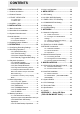
CONTENTS 1. INTRODUCTION ................................. 3 3.6 Key Lock Operation ............................... 29 1.1 Product Introduction..................................3 4. MENU SETUP....................................30 1.2 Product Features ......................................3 4.1 REC Setting ........................................... 30 1.3. FRONT / REAR VIEW .............................4 4.2 ALARM / MOTION Setting ..................... 31 1.3.1 Front View ..........................
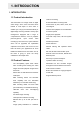
1. INTRODUCTION 1. INTRODUCTION 1.1 Product Introduction levels for recording. This DVR-3024 is a storage media of digital Event/Timer/Alarm recording mode. video image, which uses hard disk drives Quick search by time, alarm, event, and instead of VCR tapes to store video. It recording list. enables you to enjoy the extreme flexibility of Fast and slow playback of recorded video digital image archiving instead of clumsy tape at various speeds. management.
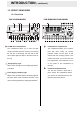
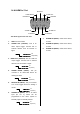
INTRODUCTION ( continued ) 1.3. FRONT / REAR VIEW 1.3.1 Front View FOR CD-ROM MODEL FOR REMOVABLE HDD MODEL 1 23 2 24 3 4 5 PLAY STOP PAUSE REC 6 REV FWD ZOOM Power Display Setup Search Enter Seq./Save A-rec T-rec DISK 7 1 CD-RW device compartment: 1 8 9 10 11 14 13 12 15 16 17 18 19 Power 20 21 22 Hard-disk drive compartment: The compartment allows you to burn the data The compartment allows you to install a mostly for backup purposes.
3 PAUSE button: In a playback display, press this to freeze the display. During the freeze, press it to display one frame/field of a picture at a time in the forward direction. (Illuminate green in PAUSE mode.) 4 PLAY button: Press to play back a recorded video from the hard disk. (Illuminate green in PLAY mode.) 5 STOP button: Press to stop playing back a recorded video. (Illuminate green in STOP mode.) 6 REC button: Push to start recording video into a hard disk while in the live display mode.
the hard-disk drive is storing or retrieving data. The red light signals the hard-disk drive is filling up. The orange light indicates the hard-disk is retrieving at disk-full status. 20 Shuttle Ring: The shuttle can be moved forward and backward for playback in either direction. Turn this left to play a recorded video in the reverse direction at faster or slower speeds than the recorded speed.
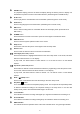
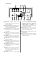
1.3.2 Rear View 25 26 27 28 IN hi-z OUT 75 SD Card RS-485 IN RS-232 ETHERNET OUT MONITOR AUDIO 29 30 25 26 ALARM 31 32 33 connectors are used to connect the video ALARM OUT, DISK FULL, RECORD IN, output from a camera ALARM Hi-Z/75 Ω Individual termination: These 4 connecting with external devices.
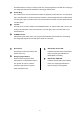
1.4 ALARM In / Out DISK FULL ALARM OUT ALARM RESET RECORD IN GROUND 5 4 9 3 8 2 7 1 6 ALARM1 IN ALARM4 IN ALARM2 IN ALARM3 IN The above figure is the rear view. 7. for CH 3 1. GND: Ground Contact. 2. ALARM OUT (OUTPUT): This is an 8. external devices such as buzzers or 9. 5V 0V(Active) 3. DISK FULL (OUTPUT): This is a disk full output trigger. Connect this to external devices such as buzzers or lights.
2. INSTALLATION 2. INSTALLATION Please follow the instruction and the diagram below to set up the system. 2.1 Basic Connection A. CONNECTING WITH 1 to 4 CAMERAS Camera Camera Camera Camera IN hi-z OUT 75 SD Card RS-485 IN RS-232 ETHERNET OUT MONITOR AUDIO ALARM I/O DC12V Monitor B. ATTACHING AN EXTERNAL DEVICE TO DVR Connect an alarm out, alarm input, and a peripheral device as shown in the diagram below.
INSTALLATION ( continued ) proceeding with the recording function. The 2.2 Hard-disk Drive Installation jumper-setting arrangement of installed hard-disk drives for the system (Table 3.2 A.) is shown in the tables below. The DVR is equipped with two compartments of hard disk drive (for removable model only). The unit usually comes with one Note: The CD-RW model is equipped with a hard-disk drive installed in the compartment fixed hard- disk and a CD-RW drive.
Table 3.2 B.
2.3 System Information and Channel Selection FIGURE 3.3 A 2.3.1 System information 1+2 :59G 12.4 HR QUALITY : NTSC RATE : 20 F/S You can display system settings information as shown in FIGURE 3.3 A below at any time by pressing the Display button 8 . In the playback mode, the recorded video information HD 1 2 is displayed. In the live or recording mode, the Manual Recording information is displayed. SIZE 20G 39G REC 10.0% 0.
5. Restart the unit when the device sounds a tone twice Mode Key Live / Quad Record ( Result Display the message “PLEASE (If you have already followed the procedures 1~5, and the unit is still unable to switch on, please first ( Single channel ) check if the SD card you are using is functioning CH2/ and the file is intact. And then start procedures 1 CH3/ ~ 5 all over again.) CH4 6. Verify the version of the system software. (Please Seq./ refer to the section 4.6 VERSION option.
3. OPERATIONS 3. OPERATIONS hard-disk drive will normally be filled in 3.7 hours (see the gray area in the table). If the total This section shows you how to operate and capacity of 80GB hard-disk drives is in use under manage the DVR when it gets in the way. the same refresh rate and picture quality, it will be 3.1 Configuring Recording Settings filled in 14.8 hours (4 times the rate of a 20GB hard-disk drive).
OPERATIONS ( continued ) PAL (Audio OFF) BEST HIGH STANDARD BASIC Refresh Rate (Frame/Sec) REC Time Mode Image Quality 3.4 3.6 4.5 5.7 6.0 7.2 9.0 11.4 25 12.5 8.3 5 2.7 1.4 0.76 0.44 3 hr 6 hr 9 hr 12 hr 24 hr 48 hr 96 hr 168 hr 3.4 3.5 4.4 5.6 5.9 7.1 8.8 11.1 25 12.5 8.3 5 2.7 1.4 0.76 0.
3.2 Recording Operations (2) Select the CLOCK / TIMER and press the This section details the way to record video Enter button into hard-disk drives. Before commencing with TIMER page. 15 to enter the CLOCK / the recording function, please configure the (3) Select the TIMER-SET. recording setting properly according to your (4) Press the Enter button needs. 15 to enter the REC SCHEDULE table. 3.2.
(8) Press the REC button 6 set ALM OPERATION to ON/ OFF. for 3 seconds during the scheduled recording to stop it any MAIN MENU time. If you wish to continue the scheduled recording, press the REC button 6 RECORD ALARM / MOTION TIMER/ SEQ/ TITLE COMMUNICATION DISK SYSTEM to proceed.
3.2.4 Externally Triggered Recording By connecting the RECORD IN of ALARM I/O on the rear panel of the DVR, you can activate/deactivate the recording function of a DVR. The file will be kept with a prefixed “R”. NOTE: The status of recording operations when an alarm takes place is shown in the diagrams below.
3.3 Playback Operations This section shows you how to operate the fast, 3.3.2 Fast Forward/Backward slow, and single-picture playback functions, and details how the unit is to playback a file in 7 speeds available for playback: 1x, a different operation status. Please refer to the There are following paragraphs specifying the relevant 2x, 4x, 8x, 16x, 30x and 100x. details.
3.3.5 Playback Recorded Video from an HDD of the mobile rack (for removable HDD model only) Each subsequent turn of the shuttle to the right increases the forward rate, as 1/2, 1/4, 1/8, and 1/16. 20 (3) Reverse: Turn the Shuttle dial to the left to view the recorded video in the To play back a recorded video from an HD2, reverse direction at a speed slower take the following steps: than the recorded speed.
3.4 Search Operations 3.4.2 ALARM LIST Search This section shows you how to access Take the following steps to proceed with the recorded video. alarm-list search function. (1) Press the Search button 3.4.1 FULL LIST Search 10 to enter the search mode.
(3) Set the time period you wish to search for ● You can also set up by using the Shuttle the recorded video. Ring and the Jog Dial to move eye focus. 15 (4) Press the Enter button to start searching is the equal of the “<” button for and displaying the concerned image. (5) If no video is found, please return to the time-setting page and repeat steps (3) and , is the equal of the “>” button 14 , is the equal of the “^” button and is the equal of the “v” button (4) again for another search.
LEVEL 3 : Interval = 1 Min requirement and press the Enter button 15 to display the image. 15:31:00 15:30:00 15:32:00 (5) If you need another, please return to the 15:33:00 SD card JPG file list page and repeat 15:34:00 15:35:00 15:38:00 15:39:00 15:36:00 steps 3 and 4 again for another search. 15:37:00 SEARCH FULL LIST ALARM LIST TIME SEARCH THUMBNAIL SD CARD CD (For CD-RW model only) 2004:10:20 LEVEL : 3 1 MIN LEVEL 4 : Interval = 10 Sec.
requirement and press the Enter button 15 to display the image. (5) If you need another, please press the Enter button 15 to return to the CD MENU page and repeat step (4) again for another search. SEARCH FULL LIST ALARM LIST TIME SEARCH THUMBNAIL SD CARD CD (For CD-RW model only) SEARCH CD DVR0001\ DVR0002\ DVR0003\ DVR0004\ Search EXIT ^ v SELECT < PAGE UP (“CD” STANDS FOR > PAGE DOWN THE CD-ROM MODEL AND “BACKUP” INDICATES THE REMOVABLE HDD MODEL ONLY IN ITEM 6.
3.5 Backup Operations iii ) Press the Seq./Save button 3.5.1 CD Rewritable unit Backup Operations (FOR CD-ROM MODEL ONLY) and select # 3 ( "CD JPEG" ) and enter. iv ) You've entered the CD JPEG menu. v) Select item 1( “ADD” ) to add your image into the buffer. This device now includes a CD-RW unit. SAVE SAVE/CD JPEG PAUSE ADD EDIT BURN EXIT SD JPEG SD AVI CD JPEG CD AVI EXIT (1) SD JPEG: Archive single image clips into vi ) Turn the jog dial or Play button to find an SD card.
Hear that beeping signal to confirm your disc is ready. MAIN MENU RECORD ALARM / MOTION CLOCK/ TIMER COMMUNICATION DISK SYSTEM ii ) Play the video back to find your desired item. Press PAUSE when you want to start. iii ) Press the Seq./Save button and GOTO DISK PAGE select # 4 ( "CD AVI" ) and enter. iv ) You're in the CD AVI menu now.
recorded video from HD 1 to HD2. Stay on the DISK SETTING page. Use the “^” button 13 12 DISK SETTING and “v” buttons and HD REFORMAT HD2 USAGE HD BACKUP HD FAT32 SD FILE AUTO ERASE SD REFORMAT CD REFORMAT to highlight BACKUP; select ALARM, then press the Enter button 15 to proceed.
(1) Press the Setup button 9 to enter the (1) Press the Setup button setup mode and select the DISK. button to enter the setup mode and select the DISK. (2) Highlight DISK and press the Enter 15 9 (2) Highlight DISK and press the Enter to enter the DISK SETTING button page. 15 to enter the DISK SETTING page. (3) Then set SD FILE to JPEG. (3) Then set SD FILE to AVI.
3.5.5 Updating System Software 3.5.4 Backup the System setting info into an SD card. Please refer to section 2.4 for more details. The DVR offers a quick setup method by 3.6 Key Lock Operation using the SD card. If a user wants to set many DVR devices with the same settings, The Key Lock operation protects the unit the DVR could save the whole setting in the against unauthorized use by disabling the SD card, then transfer it to another DVR. entire front panel controls.
4. MENU SETUP 4. MENU SETUP 4.1 REC Setting MAIN MENU There are 6 categories for operation setting in the RECORD ALARM/ MOTION TIMER/ SEQ/ TITLE COMMUNICATION DISK SYSTEM menu setup system as shown below. The following sections will instruct you step by step how to configure the operation setting and state each menu’s purpose and options. Press the Setup button 9 to access the setup menu. Once inside GOTO REC PAGE the menu system, the on-screen menu allows you to set up the key features of the unit.
recording rates you can select from: 30F/S (30 NOTE: Audio function can only be activated at frames per second), 15F/S, 10F/S, 6F/S, the following refresh rates in NTSC(PAL): 2.7F/S, 1.2F/S, 0.61F/S, 0.35F/S, 1 F/8S, 30(25), 1F/12S, and 1F/16S. fields/sec. 15(12.5), 10(8.3), 6(5), 2.7(2.7) For a PAL unit, there are 11 different 4.2 ALARM / MOTION Setting recording rates you can select from: 25F/S (25 frame per second), 12.5F/S, 8.3F/S, 5F/S, MAIN MENU 2.7F/S, 1.4F/S, 0.76F/S, 0.
REC RATE: ALM TYPE: This option is for the purpose of adjusting the This option allows users to set a type of alarm number of pictures recorded every second input corresponding to the sensor signal in into a storage disk when an alarm input is use. activated. For an NTSC unit, there are 5 NO: Normally Open.
two periods of time each day for scheduled MOTION SETTING: The motion detection function is convenient for recording. This option allows you to set the people without an alarm trigger input, but the time each day when the DVR will start and stop function can be used with an alarm trigger recording. input at the same time.
on the last Sunday of March. Time reverts to jumping is proceed. In live mode, press the standard time at 1:00 a.m. on the last Sunday Seq./Save button to switch the screen to the on October. sequential jumping mode. SET: Sets the beginning and ending for the daylight saving time. SEQUENCER REC ENABLE: This option enables/disables the programmed CHANNEL 1 2 3 4 DWELL 03 03 03 03 03 scheduled recording. ON: Enables the scheduled recording. OFF: Disables the scheduled recording.
BAUD: MAIN MENU RECORD ALARM / MOTION CLOCK/ TIMER COMMUNICATION DISK SYSTEM You have the option of using a Baud rate ( at 8 different levels : 2400, 4800, 9600, 19200, 28800, 38400, 57600 or 115200). GOTO COMM PAGE NET ENABLE: COMM SETTING COMM ID RS232 RS485 BAUD NET ENABLE NET DHCP NET IP NET ACCOUNT FTP SETTING This option selects either enable or disable for :01 :ON :ON :2400 :OFF :OFF :SET :SET the Ethernet communication port. OFF: Disables it. ON: Enables it.
FTP IP: FTP SETTING : OFF : ALARM REC : 1F/ 1S : SET ENABLE REC MODE REC RATE FTP ACCOUNT Every FTP server has to own an IP address to be identified on the network. Enter the IP address of the FTP server. USER: Enter the FTP user name (Login Name). PASSWORD: Type in the FTP password (Password). MAIN PAGE ENABLE: PATH: This option selects either to enable or disable as options for the FTP function. Enter the upload path while connecting the ON: Enables it. FTP. OFF: Disables it. 4.
recording will automatically stop at the optimum of 300 images. NOTE: In the case of the CD-RW model you won’t see the “SD FILE” item mentioned in the menu, because it’s not used here. NOTE: To save images or videos in a CD-ROM or SD Card, please refer to section 3.5 for more details. purpose only. (This function has to be proceeded with when the HD 2 USAGE option is set to BACKUP.) NOTE: In the case of the CD-RW model, only one HD can be reformatted. No backup HD can be used.
This page is used for accessing the history of the operation status, setting the password, resuming OSD LANGUAGE: factory default, and determining the menu display This option allows you to select the OSD background. language display as English or Chinese.
SETUP PWD: When this option is on, the user must pass the password check before entering the setup menu. ON: Enables pass protection for the setup menu. OFF: Disables pass protection for the setup menu. DEFAULT: This option allows you to reload the factory default setting. Please do note that the password will not be changed in the factory default setting. SD SETUP: The DVR offers a quick setup method by using an SD card.
5. NETWORK 5. NETWORK 5.1 Network Configuration Physical Spec. of RJ-45 Cable for Ethernet Wire Type Cat. 5 5.1.1 Cable Connections Connector Type RJ-45 Please follow the instructions below to Max. Cable Length 30 m connect your DVR to a computer or a network and to choose a proper RJ-45 cable Hub Wiring Configuration Straight Through PC Wiring Configuration Cross Over configuration for connections. A. Connect to a PC Use a crossover LAN cable to connect directly to a PC.
5. NETWORK NETWORK ( continued ) highlight “NET ENABLE”; select ON. Then press the Enter button to proceed. PIN NO. 1. 2. 3. 4. 5. 6. 7. 8. PIN Assignment TX + TX RX + Not Connected Not Connected RX Not Connected Not Connected RJ-45 socket 5.1.2.2 Enable DHCP Function MAIN MENU 12345678 RECORD ALARM / MOTION CLOCK/ TIMER COMMUNICATION DISK SYSTEM GOTO COMM PAGE RJ-45 PIN configuration for LAN Hub COMM SETTING 5.1.
must be in the same class type as your network address. IP addresses are written as COMM SETTING COMM ID RS232 RS485 BAUD NET ENABLE NET DHCP NET IP NET ACCOUNT FTP SETTING four sets of numbers separated by periods; :01 :ON :ON :2400 :OFF :OFF :SET :SET for example, 192.168.0.1 Therefore, if the connected network is identified as Class C, for example, the first three sets of numbers of the DVR IP address must be the same as the network address.
5.1.3 TCP/IP Communication Setup Point to the Local Area Connection and click Follow the instructions below to install the the right bottom of the mouse. Click the TCP/IP communication program into your Properties computer. Connection. 1. to enter the Local Area Click the Start Menu from your computer, and point to the Control panel. 3. Click the Configuration tag; check if the TCP/IC is included among the network component list. If the TCP/IP is included, please process step 5.
If you are using a DHCP server, please select Obtain an IP address automatically. 5 TCP/IP Configuration setting Any assigned IP address for the connected Click Start → DVRs must be in the same class type as Control Panel → Network.Connections → Local the server. If there is no DHCP server, please select specify an IP address and Area Connection type in the IP address of your PC. This IP Select Internet Protocol (TCP/IP), address must be different from the DVR IP and then click Properties.
5.1.4 Connection Testing With the previous settings, follow the instructions below to ensure whether you have established the connection successfully. 1. Click Start → Command Programs 4. If you receive a response as in the sample screen below, you successfully made the connection. 2. Type in ping 192.168.1.1 then Enter. (See the sample screen below) ** This IP is the DVR IP address which is assigned for the connected DVR. 3.
5.2 TRIPLEX 4 CH DVR VIEWER SOFTWARE: Introduction The programs can be operated by a selected PC equipped with the following requirements: Intel Pentium III 750MHz (at least). This version of the TRIPLEX 4 CH DVR 128 MB RAM Viewer Software uses the Microsoft .Net Windows 2000, XP or above. Framework version. The .Net Framework 4 MB Video card capable of 24-bit performs the XML Web Services, which true color display. applies this operation system. The .
※Note: Please choose the "Next" button to continue. Step 6 : After completing installation, you can Step 4: The installation screen will show the double - click the file shown below. Or click the message " C:\Program Files\ Viewer "Start Menu" in the computer and select Software\". Or you can select the path you "Programs" to open the "Program Selection" want. page. Then click the "Viewer Software" tag to start the 4 - channel DVR Viewer Software Program.
search the whole local LAN 4 - channel DVR device to see a list. NOTE: If you want to create a new DVR, please button to press the add it. 5.2.2.1 Program introduction ※ Step 2: Double click your selected device to see a window as on the right. Enter the "Username" and "Password" -- the default name and password are "admin" and "9999". 【 Available Devices 】: Here the whole DVR list is shown. You can connect with your selection. Double click any of them to open the screen below.
the full screen for surveillance. All the "Print": Click the "Print Preview" button and setting buttons will be hidden in this go to the "Preview" option to adjust the mode. If you want to return to the image size. Go to the "Print Settings" area previous mode, use the mouse to click and then go to "Mark Date and Time" if you the right key, and choose "Close". wish to stamp the date and time of the image 4. Re-arrange the divisions: Click this on the image itself.
5.2.3.2.1 Remote play stopping, in one of the four designated This device has the full triplex so you can use directions. The fifth button, in the center, will the Viewer Software in the remote without stop the camera at any point you prefer. affecting the performance of the 4 - channel DVR. You can also use the Viewer Software to play and back up. If you have a PTZ camera, The left-hand set of buttons, the Viewer Software can also control it.
6. The ‘AutoPan’ section has three buttons. The ‘Start’ and ‘End’ buttons fix the two points of any panning movement you select. The third or bottom button sets the chosen movement in the play mode. 【Edit AVI】: ● File Path: To set the backup file and the file name, check the "Browser" button on the right. Click "Edit Selected File" 5.2.3.3 Backup and video edit Use the to start editing. button to see the "Backup" ● Frame Rate Modification: To see the window.
● Mark Day and Time : Sets the date and 5.2.3.4 Web Page Viewer time stamp. Play Options: This section provides instructions for using the Viewer Software to view the Web Page. ● Time to play: To search the date and time you want. ● Channel Number: To choose the camera. Play Monitor: ● Use the panel below to play or stop, etc. If you already want to back up, click the "Start backup" button. If you want to stop, click the "Stop backup" button. NOTE: This device also provides the IE Browser function.
5.2.3.5 Viewer setting 2. "Playback Record Time". Click the "Display Mode" to select from a drop down list of two choices, "Hide" and "Show". Your choice will decide whether the images will display their date and time or not. 3. "Auto Scan Interval". Here you have two entries, "Scan Working Devices" and "Scan Available Devices". Set the time in seconds for both entries as per your requirements. The "Scan Working Devices" entry has a time span of 1 to 5 seconds only.
Recorded video list box. This box Browsing images from the DVR allows you to access all recorded The images from the DVR will be displayed on video which are stored in the HDD of the home page while going online with the DVR. the connected devices. To review a There are some buttons provided at the bottom recorded video, simply select an entry from the list and click the of the home page for further setting. button. PgUp/ PgDn: Enables you to scroll up and down the list. Time & Status Box.
3. Set the TIMER RECORD to ON to enable the 3. Click the button to submit the new TIMER RECORD function. 4. There Record / Alarm setting. are two time-periods available for button to return to the scheduling each day. The Timer Record setting home page while the new image setting acts on page allows users to program the time each day the images to effect the desired changes that the DVR will start and stop recording. The instantly.
6. MISCELLANEOUS 6. MISCELLANEOUS 6.1 RS-232 & RS-485 Setup & Protocol 6.1.1 RS232 & RS485 Setup Use a Null Modem cable (the standard RS-232 9 Pin Cable with Pin 2 and Pin 3 exchanged, see pin configuration chart below for details) to connect the COM 1 on the rear panel of the DVR to a PC. Set the RS-232 option to ON in the COMMUNICATION page of the setup menu. Set the PC communication parameters: 9600 bps, No Parity, 8 Data Bits, 1 Stop Bit. 6.1.2 Communication Protocol 6.1.2.
MISCELLANEOUS ( continued ) 6.1.2.
2004/06/20 17:05:00 = <0xD4>, <0x07>, <0x06>, <0x14>, <0x11>, <0x05>, <0x00> DVR Act: Changing the time and date. D. Request State (Second Category=0x06) PC Request: <0x41>, <0x01>, <0x20>, <0x02>, <0x06>, <0x00>, <0x4f> DVR Response: <0x41>, <0x20>, <0x01>, <0x02>, <0x06>, <0x01>, , <0x4f> Description of : STATE_STOP 0 STATE_PLAY 3 STATE_SETUP 6 STATE_SEARCH 7 STATE_BACKUP 15 E.
6.2 Hard Disk Installation 4. 5. Usually, the unit comes with one hard-disk drive installed in compartment HD 1, which is default-configured as a master. The jumper settings configuration of the installed hard-disk drives for the unit and compatible Setting the jumper of your hard disk driver. Place the hard disk in The way to set the the rack. jumper of the drive varies between manufacturers; please refer to the instructions on the driver to set the jumpers in the master position.
9. Place the mobile rack back onto the device and screwing in all the 4 screws. 6.2.2 Mobile Rack (FOR REMOVABLE HDD MODEL) 1. 2. Pull the active-handle Make sure that the key outward to detach the is unlocked. carrier body from the mobile rack. 60 3. 4. Slide the top cover backward and remove. Setting the jumper of your hard disk driver. The way to set the jumper of the drive varies between manufacturers; please refer to the instructions on the driver to set the jumpers in the master position.
5. 11. 6. Lock the Key. Attach the interface Place the HDD inside connector and the mobile rack. Use four of power connector to the the provided screws. drive. Please note the red lining of the IDE cable and the red wire of power cable must line up side by side. 7. Place the top cover back to the carrier body by sliding forward to secure. 9. 8. Slide the carrier body back in the mobile rack. 10. Push the carrier body Push the active-handle further into the mobile inward.
6.
6.4 O.S.D Message No. O.S.
6.5 Time Index Table 3000 Indexes HD1 1 12-02-03 12:20:55 2 12-02-03 13:30:33 3 01-30-04 16:00:34 : : : 3000 02-03-04 16:00:56 HD1 1 12-02-03 12:20:55 2 01-30-04 16:00:34 : : : 2999 02-03-04 16:00:56 3000 02-08-04 17:30:58 3000 Indexes Previously recorded data overwritten The point stops recording Previously recorded data remaining The DVR will generate a Time Index Table data. indicating recorded data is kept in a particular approach will be applied until the disk becomes HDD.
6.
6.7 ScanIP Follow the instructions below to use the ScanIP software to search the DVR devices in a local network. 1. Click the button to discover the connection of the all-type device in the LAN. The Device List will display the connection of the all-type device. 2. Select the desired device of the DVR from the Device List. 3. Click the desired device to show the window 5. Manual insertion of “Free IP Address”.
2. To change any IP address, type in the new address in the “Free IP Address” box on the right as well as the device “Login Name” and “Password” in their respective blanks at bottom left, then click “UPDATE”, and the new address will automatically be sent to the device. 6. Auto search “Free IP Address”. If you clicked “Yes” the “Free IP Address” box will appear on the right. 9. Click “Exit” at bottom right to shut the device. 1.
3. Please do not touch the surface of the disc APPENDIX 1. – Using CD Discs (FOR CD-RW MODEL ONLY) where it has been recorded. 4. To insert the caddy please press the insert / eject button and hold the caddy lightly at the middle of its front and push gently to insert. Please note that when using CD-ROM, CD-R or CD-RW discs, do not write or stick anything on the surface as this could cause an error in Ejecting The Disc recording or the data on the disc may be damaged. 1. Press the eject button.
3. Press the front of the tray or lightly and gently pull the tray out with two fingers. Caution When you use either a CD-RW or a CD-ROM, please pay heed to the following. 1. At the time of installation: As suggested in your specifications, please do not install in an unstable position or in one that causes vibrations. 2. Do not install in high humidity, direct sunlight, or damp conditions. 3.